2008 NISSAN TEANA brake light
[x] Cancel search: brake lightPage 4931 of 5121
WCS
WCS-1
DRIVER INFORMATION & MULTIMEDIA
C
DE
F
G H
I
J
K L
M B
SECTION WCS
A
O P
CONTENTS
WARNING CHIME SYSTEM
BASIC INSPECTION ....... .............................3
DIAGNOSIS AND REPAIR WORKFLOW ..... .....3
Work Flow ........................................................... ......3
FUNCTION DIAGNOSIS ...............................5
WARNING CHIME SYSTEM .......................... .....5
WARNING CHIME SYSTEM .......................................5
WARNING CHIME SYSTEM : System Diagram . ......5
WARNING CHIME SYSTEM : System Description
......
5
WARNING CHIME SYSTEM : Component Parts
Location ............................................................... ......
6
WARNING CHIME SYSTEM : Component De-
scription .....................................................................
6
LIGHT REMINDER WARNING CHIME ................. ......6
LIGHT REMINDER WARNING CHIME : System
Diagram .....................................................................
7
LIGHT REMINDER WARNING CHIME : System
Description ................................................................
7
LIGHT REMINDER WARNING CHIME : Compo-
nent Parts Location ...................................................
8
LIGHT REMINDER WARNING CHIME : Compo-
nent Description ........................................................
8
PARKING BRAKE RELEASE WARNING CHIME ......8
PARKING BRAKE RELEASE WARNING CHIME
: System Diagram ......................................................
9
PARKING BRAKE RELEASE WARNING CHIME
: System Description .................................................
9
PARKING BRAKE RELEASE WARNING CHIME
: Component Parts Location ....................................
10
PARKING BRAKE RELEASE WARNING CHIME
: Component Description .........................................
10
DIAGNOSIS SYSTEM (METER) ........................11
Diagnosis Description ......................................... ....11
CONSULT-III Function (METER/M&A) ...................12
DIAGNOSIS SYSTEM (BCM) ...........................16
COMMON ITEM ..................................................... ....16
COMMON ITEM : CONSULT-III Function (BCM -
COMMON ITEM) .....................................................
16
BUZZER ................................................................. ....17
BUZZER : CONSULT-III Function (BCM - BUZZ-
ER) ..........................................................................
17
COMPONENT DIAGNOSIS .........................19
POWER SUPPLY AND GROUND CIRCUIT ....19
COMBINATION METER ........................................ ....19
COMBINATION METER : Diagnosis Procedure .....19
BCM (BODY CONTROL MODULE) ...................... ....19
BCM (BODY CONTROL MODULE) : Diagnosis
Procedure ............................................................ ....
19
METER BUZZER CIRCUIT ...............................21
Description ...............................................................21
Component Function Check ....................................21
Diagnosis Procedure ..............................................21
WARNING CHIME SYSTEM .............................22
Wiring Diagram - WARNING CHIME - ....................22
ECU DIAGNOSIS .........................................26
COMBINATION METER ...................................26
Reference Value .................................................. ....26
Wiring Diagram - METER - ......................................32
Fail-Safe ..................................................................39
DTC Index ...............................................................40
BCM (BODY CONTROL MODULE) .................41
Reference Value ......................................................41
Wiring Diagram - BCM - ..........................................64
Fail-safe ...................................................................70
DTC Inspection Priority Chart ...............................72
DTC Index ...............................................................73
Page 4932 of 5121

WCS-2
SYMPTOM DIAGNOSIS .............................75
THE PARKING BRAKE RELEASE WARNING
CONTINUES SOUNDING, OR DOES NOT
SOUND ..............................................................
75
Description ..............................................................75
Diagnosis Procedure ..............................................75
THE LIGHT REMINDER WARNING DOES
NOT SOUND ......................................................
76
Description ..............................................................76
Diagnosis Procedure ...............................................76
PRECAUTION ............................................77
PRECAUTIONS .................................................77
Precaution for Supplemental Restraint System
(SRS) "AIR BAG" and "SEAT BELT PRE-TEN-
SIONER" .................................................................
77
Page 4935 of 5121
WCS
WARNING CHIME SYSTEM
WCS-5
< FUNCTION DIAGNOSIS >
C
D
E
F
G
H
I
J
K
L
MB A
O
P
FUNCTION DIAGNOSIS
WARNING CHIME SYSTEM
WARNING CHIME SYSTEM
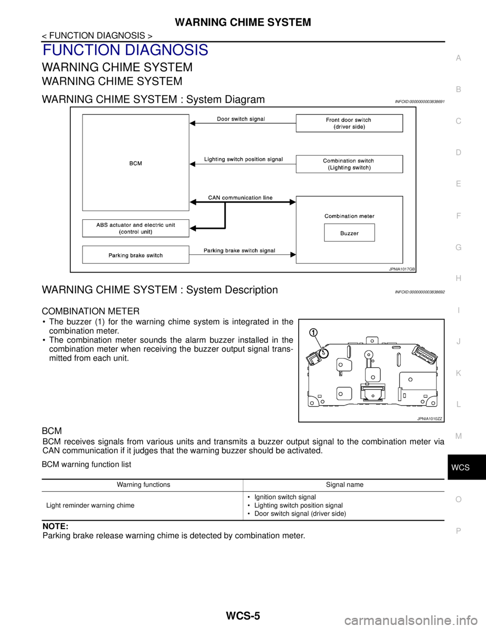
WARNING CHIME SYSTEM : System DiagramINFOID:0000000003838691
WARNING CHIME SYSTEM : System DescriptionINFOID:0000000003838692
COMBINATION METER
The buzzer (1) for the warning chime system is integrated in the
combination meter.
The combination meter sounds the alarm buzzer installed in the
combination meter when receiving the buzzer output signal trans-
mitted from each unit.
BCM
BCM receives signals from various units and transmits a buzzer output signal to the combination meter via
CAN communication if it judges that the warning buzzer should be activated.
BCM warning function list
NOTE:
Parking brake release warning chime is detected by combination meter.
JPNIA1017GB
JPNIA1010ZZ
Warning functions Signal name
Light reminder warning chime Ignition switch signal
Lighting switch position signal
Door switch signal (driver side)
Page 4936 of 5121
WCS-6
< FUNCTION DIAGNOSIS >
WARNING CHIME SYSTEM
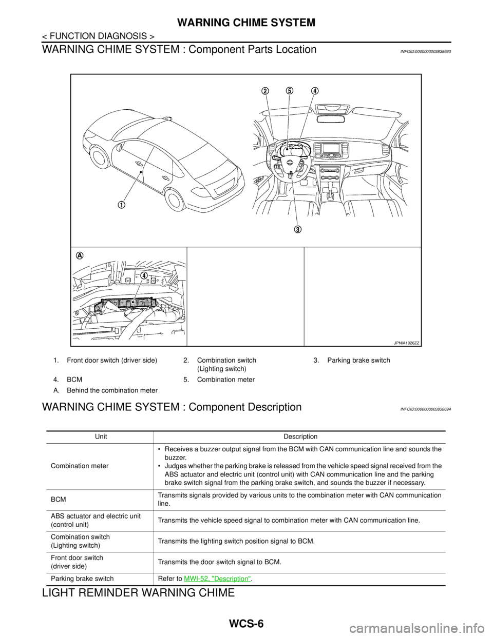
WARNING CHIME SYSTEM : Component Parts Location
INFOID:0000000003838693
WARNING CHIME SYSTEM : Component DescriptionINFOID:0000000003838694
LIGHT REMINDER WARNING CHIME
1. Front door switch (driver side) 2. Combination switch
(Lighting switch)3. Parking brake switch
4. BCM 5. Combination meter
A. Behind the combination meter
JPNIA1026ZZ
Unit Description
Combination meter Receives a buzzer output signal from the BCM with CAN communication line and sounds the
buzzer.
Judges whether the parking brake is released from the vehicle speed signal received from the
ABS actuator and electric unit (control unit) with CAN communication line and the parking
brake switch signal from the parking brake switch, and sounds the buzzer if necessary.
BCMTransmits signals provided by various units to the combination meter with CAN communication
line.
ABS actuator and electric unit
(control unit)Transmits the vehicle speed signal to combination meter with CAN communication line.
Combination switch
(Lighting switch)Transmits the lighting switch position signal to BCM.
Front door switch
(driver side)Transmits the door switch signal to BCM.
Parking brake switch Refer to MWI-52, "
Description".
Page 4938 of 5121
WCS-8
< FUNCTION DIAGNOSIS >
WARNING CHIME SYSTEM
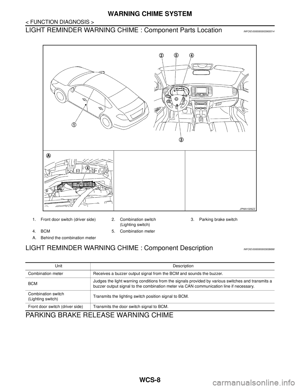
LIGHT REMINDER WARNING CHIME : Component Parts Location
INFOID:0000000003900514
LIGHT REMINDER WARNING CHIME : Component DescriptionINFOID:0000000003838698
PARKING BRAKE RELEASE WARNING CHIME
1. Front door switch (driver side) 2. Combination switch
(Lighting switch)3. Parking brake switch
4. BCM 5. Combination meter
A. Behind the combination meter
JPNIA1026ZZ
Unit Description
Combination meter Receives a buzzer output signal from the BCM and sounds the buzzer.
BCMJudges the light warning conditions from the signals provided by various switches and transmits a
buzzer output signal to the combination meter via CAN communication line if necessary.
Combination switch
(Lighting switch)Transmits the lighting switch position signal to BCM.
Front door switch (driver side) Transmits the door switch signal to BCM.
Page 4940 of 5121
WCS-10
< FUNCTION DIAGNOSIS >
WARNING CHIME SYSTEM
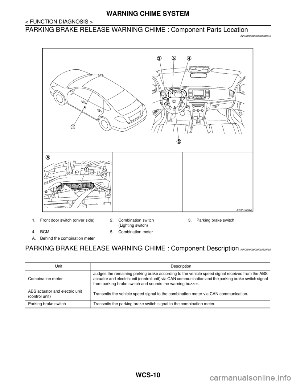
PARKING BRAKE RELEASE WARNING CHIME : Component Parts Location
INFOID:0000000003900515
PARKING BRAKE RELEASE WARNING CHIME : Component DescriptionINFOID:0000000003838702
1. Front door switch (driver side) 2. Combination switch
(Lighting switch)3. Parking brake switch
4. BCM 5. Combination meter
A. Behind the combination meter
JPNIA1026ZZ
Unit Description
Combination meterJudges the remaining parking brake according to the vehicle speed signal received from the ABS
actuator and electric unit (control unit) via CAN communication and the parking brake switch signal
from parking brake switch and sounds the warning buzzer.
ABS actuator and electric unit
(control unit)Transmits the vehicle speed signal to the combination meter via CAN communication.
Parking brake switch Transmits the parking brake switch signal to the combination meter.
Page 4943 of 5121
![NISSAN TEANA 2008 Service Manual WCS
DIAGNOSIS SYSTEM (METER)
WCS-13
< FUNCTION DIAGNOSIS >
C
D
E
F
G
H
I
J
K
L
MB A
O
P
W TEMP METER
[°C] XValue of engine coolant temperature signal is received from ECM via CAN com-
munication.
NO NISSAN TEANA 2008 Service Manual WCS
DIAGNOSIS SYSTEM (METER)
WCS-13
< FUNCTION DIAGNOSIS >
C
D
E
F
G
H
I
J
K
L
MB A
O
P
W TEMP METER
[°C] XValue of engine coolant temperature signal is received from ECM via CAN com-
munication.
NO](/manual-img/5/57391/w960_57391-4942.png)
WCS
DIAGNOSIS SYSTEM (METER)
WCS-13
< FUNCTION DIAGNOSIS >
C
D
E
F
G
H
I
J
K
L
MB A
O
P
W TEMP METER
[°C] XValue of engine coolant temperature signal is received from ECM via CAN com-
munication.
NOTE:
215 is displayed when the malfunction signal is input.
ABS W/L
[On/Off]Status of ABS warning lamp detected from ABS warning lamp signal is received
from ABS actuator and electric unit (control unit) via CAN communication.
VDC/TCS IND
[On/Off]Status of VDC OFF indicator lamp detected from VDC OFF indicator lamp signal
is received from ABS actuator and electric unit (control unit) via CAN communica-
tion.
SLIP IND
[On/Off]Status of SLIP indicator lamp detected from slip indicator lamp signal received
from ABS actuator and electric unit (control unit) via CAN communication.
BRAKE W/L
[On/Off]Status of brake warning lamp detected from brake warning lamp signal is received
from ABS actuator and electric unit (control unit) via CAN communication.
NOTE:
Displays “Off” if the brake warning lamp is illuminated when the valve check starts,
the parking brake switch is turned ON or the brake fluid level switch is turned ON.
DOOR W/L
[On/Off]Status of door warning detected from door switch signal received from BCM via
CAN communication.
TRUNK/GLAS-H
[On/Off]Status of trunk warning detected from trunk switch signal received from BCM via
CAN communication.
HI-BEAM IND
[On/Off]Status of high beam indicator lamp detected from high beam request signal is re-
ceived from BCM via CAN communication.
TURN IND
[On/Off]Status of turn indicator lamp detected from turn indicator signal is received from
BCM via CAN communication.
FR FOG IND
[On/Off]Status of front fog light indicator lamp detected from front fog light request signal
is received from BCM via CAN communication.
RR FOG IND
[On/Off]Status of rear fog light indicator lamp detected from rear fog light request signal is
received from BCM via CAN communication.
LIGHT IND
[On/Off]Status of light indicator lamp detected from position light request signal is received
from BCM via CAN communication.
OIL W/L
[On/Off]Status of oil pressure warning lamp detected from oil pressure switch signal is re-
ceived from BCM via CAN communication.
MIL
[On/Off] Status of malfunction indicator lamp detected from malfunctioning indicator lamp
signal is received from ECM via CAN communication.
CRUISE IND
[On/Off]Status of CRUISE indicator detected from ASCD status signal is received from
ECM via CAN communication.
SPORT IND
[On/Off]Status of SPORT indicator detected from sport mode switch signal is received
from control device.
4WD W/L
[On/Off]This item is displayed, but cannot be monitored.
4WD LOCK IND
[On/Off]This item is displayed, but cannot be monitored.
FUEL W/L
[On/Off]Low-fuel warning lamp status detected by the identified fuel level.
WASHER W/L
[On/Off]This item is displayed, but cannot be monitored.
KEY G/Y W/L
[On/Off]Status of key warning lamp (G/Y) detected from key warning signal is received
from BCM via CAN communication.
AFS OFF IND
[On/Off]This item is displayed, but cannot be monitored.
LCD
[B&P N, B&P I, ID NG, ROTAT, SFT
P, INSRT, BATT, NO KY,OUTKY, LK
WN]Displays status of Intelligent Key system warning detected from meter display sig-
nal is received from BCM via CAN communication.
Display item [Unit]MAIN
SIGNALSDescription
Page 4944 of 5121
WCS-14
< FUNCTION DIAGNOSIS >
DIAGNOSIS SYSTEM (METER)
NOTE:
Some items are not available according to vehicle specification.
SPECIAL FUNCTION
Special menu
W/L ON HISTORY
Stores histories when warning/indicator lamp is turned on.
“W/L ON HISTORY” indicates the “TIME” when the warning/ indicator lamp is turned on.
The “TIME” above is :
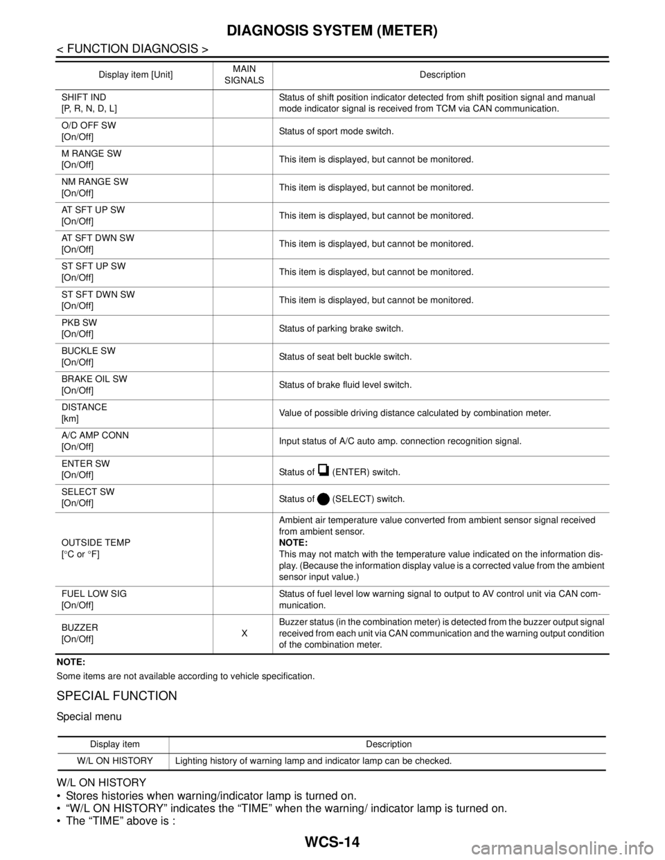
SHIFT IND
[P, R, N, D, L]Status of shift position indicator detected from shift position signal and manual
mode indicator signal is received from TCM via CAN communication.
O/D OFF SW
[On/Off] Status of sport mode switch.
M RANGE SW
[On/Off]This item is displayed, but cannot be monitored.
NM RANGE SW
[On/Off]This item is displayed, but cannot be monitored.
AT SFT UP SW
[On/Off]This item is displayed, but cannot be monitored.
AT SFT DWN SW
[On/Off]This item is displayed, but cannot be monitored.
ST SFT UP SW
[On/Off]This item is displayed, but cannot be monitored.
ST SFT DWN SW
[On/Off]This item is displayed, but cannot be monitored.
PKB SW
[On/Off]Status of parking brake switch.
BUCKLE SW
[On/Off]Status of seat belt buckle switch.
BRAKE OIL SW
[On/Off]Status of brake fluid level switch.
DISTANCE
[km]Value of possible driving distance calculated by combination meter.
A/C AMP CONN
[On/Off]Input status of A/C auto amp. connection recognition signal.
ENTER SW
[On/Off]Status of (ENTER) switch.
SELECT SW
[On/Off]Status of (SELECT) switch.
OUTSIDE TEMP
[°C or °F]Ambient air temperature value converted from ambient sensor signal received
from ambient sensor.
NOTE:
This may not match with the temperature value indicated on the information dis-
play. (Because the information display value is a corrected value from the ambient
sensor input value.)
FUEL LOW SIG
[On/Off]Status of fuel level low warning signal to output to AV control unit via CAN com-
munication.
BUZZER
[On/Off]XBuzzer status (in the combination meter) is detected from the buzzer output signal
received from each unit via CAN communication and the warning output condition
of the combination meter. Display item [Unit]MAIN
SIGNALSDescription
Display item Description
W/L ON HISTORY Lighting history of warning lamp and indicator lamp can be checked.