2008 NISSAN TEANA change time
[x] Cancel search: change timePage 2340 of 5121
![NISSAN TEANA 2008 Service Manual BCM (BODY CONTROL MODULE)
EXL-311
< ECU DIAGNOSIS >[HALOGEN TYPE]
C
D
E
F
G
H
I
J
K
MA
B
EXL
N
O
PHIGH FLASHER OPERATION
BCM detects the turn signal lamp circuit status by the current value.
BCM incre NISSAN TEANA 2008 Service Manual BCM (BODY CONTROL MODULE)
EXL-311
< ECU DIAGNOSIS >[HALOGEN TYPE]
C
D
E
F
G
H
I
J
K
MA
B
EXL
N
O
PHIGH FLASHER OPERATION
BCM detects the turn signal lamp circuit status by the current value.
BCM incre](/manual-img/5/57391/w960_57391-2339.png)
BCM (BODY CONTROL MODULE)
EXL-311
< ECU DIAGNOSIS >[HALOGEN TYPE]
C
D
E
F
G
H
I
J
K
MA
B
EXL
N
O
PHIGH FLASHER OPERATION
BCM detects the turn signal lamp circuit status by the current value.
BCM increases the turn signal lamp blinking speed if the bulb or harness open is detected with the turn signal
lamp operating.
NOTE:
The blinking speed is normal while activating the hazard warning lamp.
DTC Inspection Priority ChartINFOID:0000000003959699
If some DTCs are displayed at the same time, perform inspections one by one based on the following priority
chart.
B2608: STARTER RELAY Inhibit engine cranking500 ms after the following signal communication status becomes
consistent
Starter motor relay control signal
Starter relay status signal (CAN)
B2609: S/L STATUS Inhibit engine cranking
Inhibit steering lockWhen the following steering lock conditions agree
BCM steering lock control status
Steering lock condition No. 1 signal status
Steering lock condition No. 2 signal status
B260A: IGNITION RELAY Inhibit engine cranking500 ms after the following conditions are fulfilled
IGN relay (IPDM E/R) control signal: OFF (Battery voltage)
Ignition ON signal (CAN to IPDM E/R): OFF (Request signal)
Ignition ON signal (CAN from IPDM E/R): OFF (Condition signal)
B260F: ENG STATE SIG LOSTMaintains the power supply
position attained at the time
of DTC detectionWhen any of the following conditions is fulfilled
Power position changes to ACC
Receives engine status signal (CAN)
B2612: S/L STATUS Inhibit engine cranking
Inhibit steering lockWhen any of the following conditions is fulfilled
Steering lock unit status signal (CAN) is received normally
The BCM steering lock control status matches the steering lock
status recognized by the steering lock unit status signal (CAN
from IPDM E/R)
B2617: STARTER RELAY CIRC Inhibit engine cranking1 second after the starter motor relay control inside BCM becomes
normal
B2618: BCM Inhibit engine cranking1 second after the ignition relay (IPDM E/R) control inside BCM be-
comes normal
B2619: BCM Inhibit engine cranking1 second after the steering lock unit power supply output control in-
side BCM becomes normal
B261E: VEHICLE TYPE Inhibit engine cranking BCM initialization
B26E1: ENG STATE NO RES Inhibit engine crankingWhen any of the following conditions is fulfilled
Power position changes to ACC
Receives engine status signal (CAN)
B26E9: S/L STATUS Inhibit engine cranking
Inhibit steering lockWhen BCM transmits the LOCK request signal to steering lock unit,
and receives LOCK response signal from steering lock unit, the fol-
lowing conditions is fulfilled
Steering condition No. 1 signal: LOCK (0 V)
Steering condition No. 2 signal: LOCK (Battery voltage) Display contents of CONSULT Fail-safe Cancellation
Priority DTC
1 B2562: LOW VOLTAGE
2 U1000: CAN COMM CIRCUIT
U1010: CONTROL UNIT (CAN)
3 B2190: NATS ANTENNA AMP
B2191: DIFFERENCE OF KEY
B2192: ID DISCORD BCM-ECM
B2193: CHAIN OF BCM-ECM
Page 2356 of 5121
![NISSAN TEANA 2008 Service Manual IPDM E/R (INTELLIGENT POWER DISTRIBUTION MODULE ENGINE ROOM)
EXL-327
< ECU DIAGNOSIS >[HALOGEN TYPE]
C
D
E
F
G
H
I
J
K
MA
B
EXL
N
O
P
NOTE:
This operation status can be confirmed on the IPDM E/R “Da NISSAN TEANA 2008 Service Manual IPDM E/R (INTELLIGENT POWER DISTRIBUTION MODULE ENGINE ROOM)
EXL-327
< ECU DIAGNOSIS >[HALOGEN TYPE]
C
D
E
F
G
H
I
J
K
MA
B
EXL
N
O
P
NOTE:
This operation status can be confirmed on the IPDM E/R “Da](/manual-img/5/57391/w960_57391-2355.png)
IPDM E/R (INTELLIGENT POWER DISTRIBUTION MODULE ENGINE ROOM)
EXL-327
< ECU DIAGNOSIS >[HALOGEN TYPE]
C
D
E
F
G
H
I
J
K
MA
B
EXL
N
O
P
NOTE:
This operation status can be confirmed on the IPDM E/R “Data Monitor” that displays “BLOCK” for the item
“WIP PROT” while the wiper is stopped.
STARTER MOTOR PROTECTION FUNCTION
IPDM E/R turns OFF the starter control relay to protect the starter motor when the starter control relay remains
active for 90 seconds.
DTC IndexINFOID:0000000003894353
NOTE:
The details of time display are as follows.
- CRNT: A malfunction is detected now
- PAST: A malfunction was detected in the past.
IGN counter is displayed on FFD (Freeze Frame data).
- The number is 0 when is detected now
- The number increases like 1 → 2 ··· 38 → 39 after returning to the normal condition whenever IGN OFF →
ON.
- The number is fixed to 39 until the self-diagnosis results are erased if it is over 39.
×: Applicable
Ignition switch Front wiper switch Front wiper auto stop signal
ONOFFThe front wiper auto stop signal (stop posi-
tion) cannot be input for 10 seconds.
ONThe front wiper auto stop signal does not
change for 10 seconds.
CONSULT display Fail-safe Refer to
No DTC is detected.
further testing
may be required.——
U1000: CAN COMM CIRCUIT×PCS-16
B2098: IGN RELAY ON×PCS-17
B2099: IGN RELAY OFF —PCS-18
B2108: STRG LCK RELAY ON —SEC-96
B2109: STRG LCK RELAY OFF —SEC-97
B210A: STRG LCK STATE SW —SEC-98
B210B: START CONT RLY ON —SEC-102
B210C: START CONT RLY OFF —SEC-103
B210D: STARTER RELAY ON —SEC-104
B210E: STARTER RELAY OFF —SEC-105
B210F: INTRLCK/PNP SW ON —SEC-107
B2110: INTRLCK/PNP SW OFF —SEC-109
Page 2394 of 5121

SQUEAK AND RATTLE TROUBLE DIAGNOSES
EXT-5
< SYMPTOM DIAGNOSIS >
C
D
E
F
G
H
I
J
L
MA
B
EXT
N
O
P
Again, pressing on the components to stop the noise while duplicating the conditions can isolate most of these
incidents. Repairs usually consist of insulating with felt cloth tape.
SEATS
When isolating seat noise it is important to note the position the seat is in and the load placed on the seat
when the noise occurs. These conditions must duplicated when verifying and isolating the cause of the noise.
Cause of seat noise include:
1. Headrest rods and holder
2. A squeak between the seat pad cushion and frame
3. Rear seatback lock and bracket
These noises can be isolated by moving or pressing on the suspected components while duplicating the con-
ditions under which the noise occurs. Most of these incidents can be repaired by repositioning the component
or applying urethane tape to the contact area.
UNDERHOOD
Some interior noise may be caused by components under the hood or on the engine wall. The noise is then
transmitted into the passenger compartment.
Causes of transmitted underhood noise include:
1. Any component mounted to the engine wall
2. Components that pass through the engine wall
3. Engine wall mounts and connectors
4. Loose radiator mounting pins
5. Hood bumpers out of adjustment
6. Hood striker out of adjustment
These noises can be difficult to isolate since they cannot be reached from the interior of the vehicle. The best
method is to secure, move or insulate one component at a time and test drive the vehicle. Also, engine RPM
or load can be changed to isolate the noise. Repairs can usually be made by moving, adjusting, securing, or
insulating the component causing the noise.
Page 2523 of 5121

GI-30
< PRECAUTION >
LIFTING POINT
LIFTING POINT
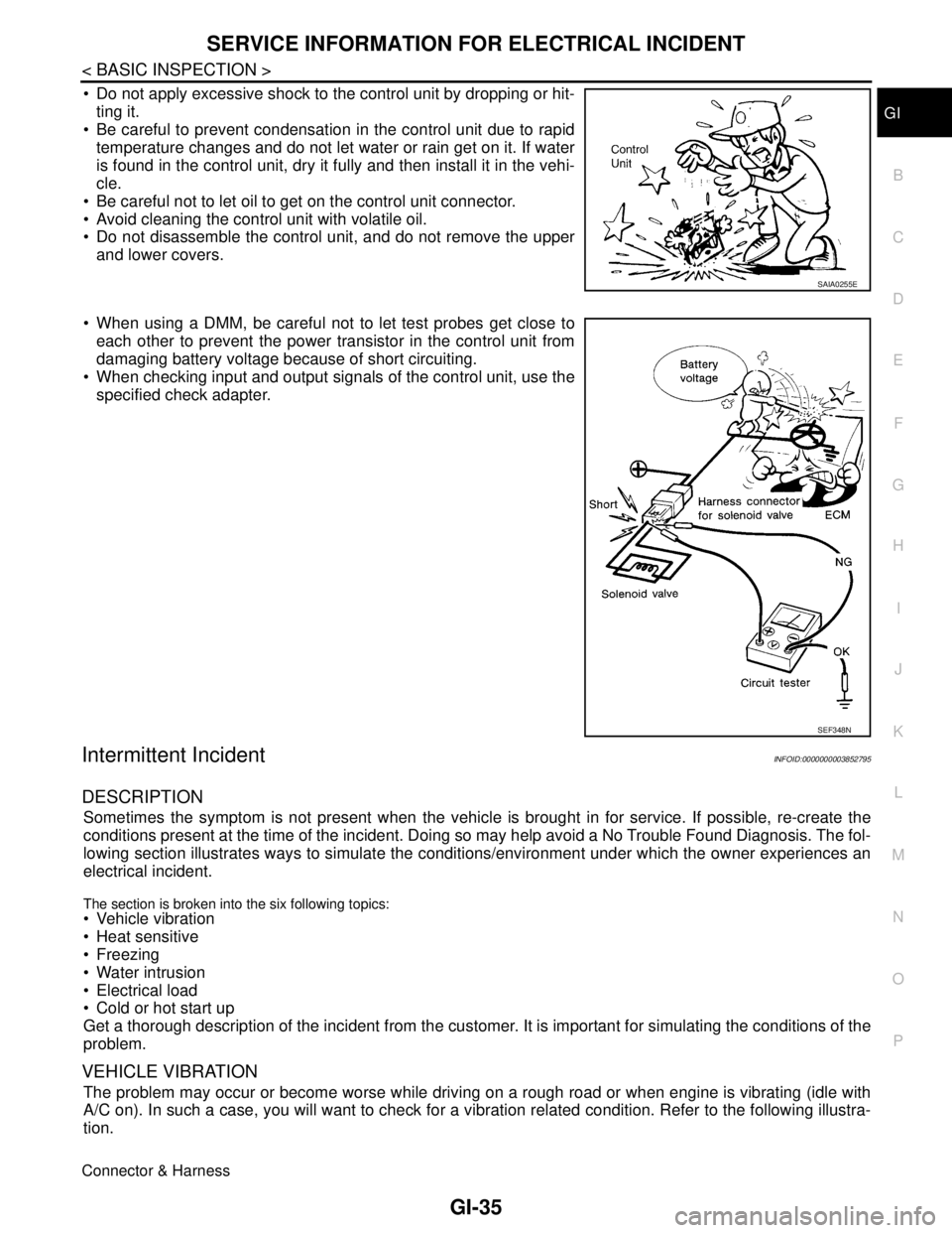
Commercial Service ToolsINFOID:0000000003852788
CAUTION:
Every time the vehicle is lifted up, maintain the complete vehicle curb condition.
Since the vehicle's center of gravity changes when removing main parts on the front side (engine,
transmission, suspension etc.), support a jack up point on the rear side garage jack with a mission
jack or equivalent.
Since the vehicle's center of gravity changes when removing main parts on the rear side (rear axle,
suspension, etc.), support a jack up point on the front side garage jack with a mission jack or equiv-
alent.
Be careful not to smash or do not do anything that would affect piping parts.
Garage Jack and Safety Stand and 2-Pole LiftINFOID:0000000003852789
WARNING:
Park the vehicle on a level surface when using the jack. Make sure to avoid damaging pipes, tubes,
etc. under the vehicle.
Never get under the vehicle while it is supported only by the jack. Always use safety stands when
you have to get under the vehicle.
Place wheel chocks at both front and back of the wheels on the ground.
When lifting the vehicle, open the lift arms as wide as possible and ensure that the front and rear of
the vehicle are well balanced.
When setting the lift arm, do not allow the arm to contact the brake tubes, brake cable, fuel lines and
sill spoiler.
Tool name Description
Board on attachment
Safety stand attachment
S-NT001
S-NT002
Page 2528 of 5121

SERVICE INFORMATION FOR ELECTRICAL INCIDENT
GI-35
< BASIC INSPECTION >
C
D
E
F
G
H
I
J
K
L
MB
GI
N
O
P
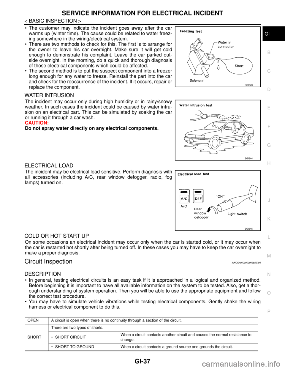
Do not apply excessive shock to the control unit by dropping or hit-
ting it.
Be careful to prevent condensation in the control unit due to rapid
temperature changes and do not let water or rain get on it. If water
is found in the control unit, dry it fully and then install it in the vehi-
cle.
Be careful not to let oil to get on the control unit connector.
Avoid cleaning the control unit with volatile oil.
Do not disassemble the control unit, and do not remove the upper
and lower covers.
When using a DMM, be careful not to let test probes get close to
each other to prevent the power transistor in the control unit from
damaging battery voltage because of short circuiting.
When checking input and output signals of the control unit, use the
specified check adapter.
Intermittent IncidentINFOID:0000000003852795
DESCRIPTION
Sometimes the symptom is not present when the vehicle is brought in for service. If possible, re-create the
conditions present at the time of the incident. Doing so may help avoid a No Trouble Found Diagnosis. The fol-
lowing section illustrates ways to simulate the conditions/environment under which the owner experiences an
electrical incident.
The section is broken into the six following topics: Vehicle vibration
Heat sensitive
Freezing
Water intrusion
Electrical load
Cold or hot start up
Get a thorough description of the incident from the customer. It is important for simulating the conditions of the
problem.
VEHICLE VIBRATION
The problem may occur or become worse while driving on a rough road or when engine is vibrating (idle with
A/C on). In such a case, you will want to check for a vibration related condition. Refer to the following illustra-
tion.
Connector & Harness
SAIA0255E
SEF348N
Page 2530 of 5121

SERVICE INFORMATION FOR ELECTRICAL INCIDENT
GI-37
< BASIC INSPECTION >
C
D
E
F
G
H
I
J
K
L
MB
GI
N
O
P
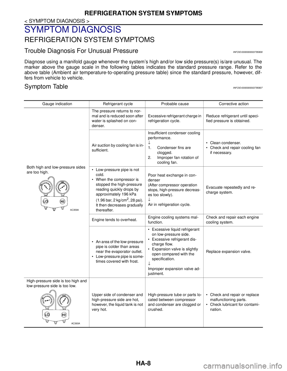
The customer may indicate the incident goes away after the car
warms up (winter time). The cause could be related to water freez-
ing somewhere in the wiring/electrical system.
There are two methods to check for this. The first is to arrange for
the owner to leave his car overnight. Make sure it will get cold
enough to demonstrate his complaint. Leave the car parked out-
side overnight. In the morning, do a quick and thorough diagnosis
of those electrical components which could be affected.
The second method is to put the suspect component into a freezer
long enough for any water to freeze. Reinstall the part into the car
and check for the reoccurrence of the incident. If it occurs, repair or
replace the component.
WATER INTRUSION
The incident may occur only during high humidity or in rainy/snowy
weather. In such cases the incident could be caused by water intru-
sion on an electrical part. This can be simulated by soaking the car
or running it through a car wash.
CAUTION:
Do not spray water directly on any electrical components.
ELECTRICAL LOAD
The incident may be electrical load sensitive. Perform diagnosis with
all accessories (including A/C, rear window defogger, radio, fog
lamps) turned on.
COLD OR HOT START UP
On some occasions an electrical incident may occur only when the car is started cold, or it may occur when
the car is restarted hot shortly after being turned off. In these cases you may have to keep the car overnight to
make a proper diagnosis.
Circuit InspectionINFOID:0000000003852796
DESCRIPTION
In general, testing electrical circuits is an easy task if it is approached in a logical and organized method.
Before beginning it is important to have all available information on the system to be tested. Also, get a thor-
ough understanding of system operation. Then you will be able to use the appropriate equipment and follow
the correct test procedure.
You may have to simulate vehicle vibrations while testing electrical components. Gently shake the wiring
harness or electrical component to do this.
SGI843
SGI844
SGI845
OPEN A circuit is open when there is no continuity through a section of the circuit.
SHORTThere are two types of shorts.
SHORT CIRCUITWhen a circuit contacts another circuit and causes the normal resistance to
change.
SHORT TO GROUND When a circuit contacts a ground source and grounds the circuit.
Page 2548 of 5121

SQUEAK AND RATTLE TROUBLE DIAGNOSES
GW-5
< SYMPTOM DIAGNOSIS >
C
D
E
F
G
H
I
J
L
MA
B
GW
N
O
P
Again, pressing on the components to stop the noise while duplicating the conditions can isolate most of these
incidents. Repairs usually consist of insulating with felt cloth tape.
SEATS
When isolating seat noise it is important to note the position the seat is in and the load placed on the seat
when the noise occurs. These conditions should be duplicated when verifying and isolating the cause of the
noise.
Cause of seat noise include:
1. Headrest rods and holder
2. A squeak between the seat pad cushion and frame
3. Rear seatback lock and bracket
These noises can be isolated by moving or pressing on the suspected components while duplicating the con-
ditions under which the noise occurs. Most of these incidents can be repaired by repositioning the component
or applying urethane tape to the contact area.
UNDERHOOD
Some interior noise may be caused by components under the hood or on the engine wall. The noise is then
transmitted into the passenger compartment.
Causes of transmitted underhood noise include:
1. Any component mounted to the engine wall
2. Components that pass through the engine wall
3. Engine wall mounts and connectors
4. Loose radiator mounting pins
5. Hood bumpers out of adjustment
6. Hood striker out of adjustment
These noises can be difficult to isolate since they cannot be reached from the interior of the vehicle. The best
method is to secure, move or insulate one component at a time and test drive the vehicle. Also, engine RPM
or load can be changed to isolate the noise. Repairs can usually be made by moving, adjusting, securing, or
insulating the component causing the noise.
Page 2577 of 5121

HA-8
< SYMPTOM DIAGNOSIS >
REFRIGERATION SYSTEM SYMPTOMS
SYMPTOM DIAGNOSIS
REFRIGERATION SYSTEM SYMPTOMS
Trouble Diagnosis For Unusual PressureINFOID:0000000003795806
Diagnose using a manifold gauge whenever the system’s high and/or low side pressure(s) is/are unusual. The
marker above the gauge scale in the following tables indicates the standard pressure range. Refer to the
above table (Ambient air temperature-to-operating pressure table) since the standard pressure, however, dif-
fers from vehicle to vehicle.
Symptom TableINFOID:0000000003795807
Gauge indication Refrigerant cycle Probable cause Corrective action
Both high and low-pressure sides
are too high.The pressure returns to nor-
mal and is reduced soon after
water is splashed on con-
denser.Excessive refrigerant charge in
refrigeration cycle.Reduce refrigerant until speci-
fied pressure is obtained.
Air suction by cooling fan is in-
sufficient.Insufficient condenser cooling
performance.
↓
1. Condenser fins are
clogged.
2. Improper fan rotation of
cooling fan. Clean condenser.
Check and repair cooling fan
if necessary.
Low-pressure pipe is not
cold.
When the compressor is
stopped the high-pressure
reading quickly drops by
approximately 196 kPa
(1.96 bar, 2 kg/cm
2, 28 psi).
It then decreases gradually
thereafter.Poor heat exchange in con-
denser
(After compressor operation
stops, high-pressure decreas-
es too slowly).
↓
Air in refrigeration cycle.Evacuate repeatedly and re-
charge system.
Engine tends to overheat.Engine cooling systems mal-
function.Check and repair each engine
cooling system.
An area of the low-pressure
pipe is colder than areas
near the evaporator outlet.
Low-pressure pipe is some-
times covered with frost. Excessive liquid refrigerant
on low-pressure side.
Excessive refrigerant dis-
charge flow.
Expansion valve is slightly
open compared with the
specification.
↓
Improper expansion valve ad-
justment.Replace expansion valve.
High-pressure side is too high and
low-pressure side is too low.
Upper side of condenser and
high-pressure side are hot,
however, the liquid tank is not
very hot.High-pressure tube or parts lo-
cated between compressor
and condenser are clogged or
crushed. Check and repair or replace
malfunctioning parts.
Check lubricant for contami-
nation.
AC359A
AC360A