2008 NISSAN TEANA battery location
[x] Cancel search: battery locationPage 2825 of 5121
![NISSAN TEANA 2008 Service Manual MAGNET CLUTCH
HAC-197
< COMPONENT DIAGNOSIS >[WITH 7 INCH DISPLAY]
C
D
E
F
G
H
J
K
L
MA
B
HAC
N
O
P
MAGNET CLUTCH
DescriptionINFOID:0000000003884776
The magnet clutch drives the compressor, by an IPDM NISSAN TEANA 2008 Service Manual MAGNET CLUTCH
HAC-197
< COMPONENT DIAGNOSIS >[WITH 7 INCH DISPLAY]
C
D
E
F
G
H
J
K
L
MA
B
HAC
N
O
P
MAGNET CLUTCH
DescriptionINFOID:0000000003884776
The magnet clutch drives the compressor, by an IPDM](/manual-img/5/57391/w960_57391-2824.png)
MAGNET CLUTCH
HAC-197
< COMPONENT DIAGNOSIS >[WITH 7 INCH DISPLAY]
C
D
E
F
G
H
J
K
L
MA
B
HAC
N
O
P
MAGNET CLUTCH
DescriptionINFOID:0000000003884776
The magnet clutch drives the compressor, by an IPDM E/R signal.
Component Function CheckINFOID:0000000003884777
1.FUNCTION INSPECTION
1. Press AUTO switch.
2. “AUTO” is indicated on the display.
3. Check that the indicator of the A/C switch turns on. Check visually and by sound that the compressor is
operating (the discharge air temperature or fan speed varies depending on the ambient temperature, in-
vehicle temperature, and temperature setting).
4. Press the A/C switch.
5. Check that the indicator of the A/C switch turns OFF. Check visually and by sound that the compressor
stops.
Does it operate normally?
YES >> INSPECTION END
NO >> Perform trouble diagnosis for the compressor. Refer to HAC-197, "
Diagnosis Procedure".
Diagnosis ProcedureINFOID:0000000003884778
1.INSPECTION IN AUTO ACTIVE TEST MODE
Perform “AUTO ACTIVE TEST”. Refer to PCS-11, "
Diagnosis Description".
Does it operate normally?
YES >> GO TO 5.
NO >> GO TO 2.
2.CHECK MAGNET CLUTCH
1. Turn the ignition switch OFF.
2. Disconnect the magnet clutch connector.
3. Directly apply the battery voltage to the magnet clutch. Check for operation visually and by sound.
Does it operate normally?
YES >> GO TO 3.
NO >> Replace the compressor.
3.CHECK MAGNET CLUTCH CIRCUIT CONTINUITY
1. Turn the ignition switch OFF.
2. Disconnect IPDM E/R connector.
3. Check continuity between magnet clutch harness connector and IPDM E/R harness connector.
Is the inspection result normal?
YES >> GO TO 4.
NO >> Repair harness or connector.
4.CHECK FUSE
Check 10A fuse (No. 49).
NOTE:
Refer to PG-101, "
Fuse, Connector and Terminal Arrangement" for fuse location.
Is the inspection result normal?
YES >> Replace IPDM E/R.
NO >> Replace the fuse after repairing the applicable circuit.
IPDM E/R Compressor
Continuity
Connector Terminal Connector Terminal
F12 48 F18 1 Existed
Page 2880 of 5121

INL-1
DRIVER CONTROLS
C
D
E
F
G
H
I
J
K
M
SECTION INL
A
B
INL
N
O
P
CONTENTS
INTERIOR LIGHTING SYSTEM
BASIC INSPECTION ....................................3
DIAGNOSIS AND REPAIR WORKFLOW ..........3
Work Flow .................................................................3
FUNCTION DIAGNOSIS ...............................5
INTERIOR ROOM LAMP CONTROL SYSTEM
.....
5
System Diagram ........................................................5
System Description ...................................................5
Component Parts Location ........................................7
Component Description ............................................8
INTERIOR ROOM LAMP BATTERY SAVER
SYSTEM ..............................................................
9
System Diagram ........................................................9
System Description ...................................................9
Component Parts Location ......................................10
Component Description ..........................................10
ILLUMINATION CONTROL SYSTEM ................12
System Diagram ......................................................12
System Description .................................................12
Component Parts Location ......................................13
Component Description ...........................................13
DIAGNOSIS SYSTEM (BCM) ............................14
COMMON ITEM .........................................................14
COMMON ITEM : CONSULT-III Function (BCM -
COMMON ITEM) .....................................................
14
INT LAMP ..................................................................15
INT LAMP : CONSULT-III Function (BCM - INT
LAMP) .....................................................................
16
BATTERY SAVER .....................................................17
BATTERY SAVER : CONSULT-III Function (BCM
- BATTERY SAVER) ...............................................
17
COMPONENT DIAGNOSIS .........................19
POWER SUPPLY AND GROUND CIRCUIT ....19
BCM ...........................................................................19
BCM : Diagnosis Procedure ....................................19
INTERIOR ROOM LAMP POWER SUPPLY
CIRCUIT ............................................................
20
Description ...............................................................20
Component Function Check ....................................20
Diagnosis Procedure ...............................................20
INTERIOR ROOM LAMP CONTROL CIRCUIT
...
22
Description ...............................................................22
Component Function Check ....................................22
Diagnosis Procedure ...............................................22
STEP LAMP CIRCUIT .......................................24
Description ...............................................................24
Component Function Check ....................................24
Diagnosis Procedure ...............................................24
TRUNK ROOM LAMP CIRCUIT .......................26
Description ...............................................................26
Component Function Check ....................................26
Diagnosis Procedure ...............................................26
PUSH-BUTTON IGNITION SWITCH ILLUMI-
NATION CIRCUIT .............................................
28
Description ...............................................................28
Component Function Check ....................................28
Diagnosis Procedure ...............................................28
INTERIOR ROOM LAMP CONTROL SYSTEM
...
30
Wiring Diagram - INTERIOR ROOM LAMP - ..........30
ILLUMINATION .................................................39
Wiring Diagram - ILLUMINATION - .........................39
ECU DIAGNOSIS .........................................53
Page 2889 of 5121

INL-10
< FUNCTION DIAGNOSIS >
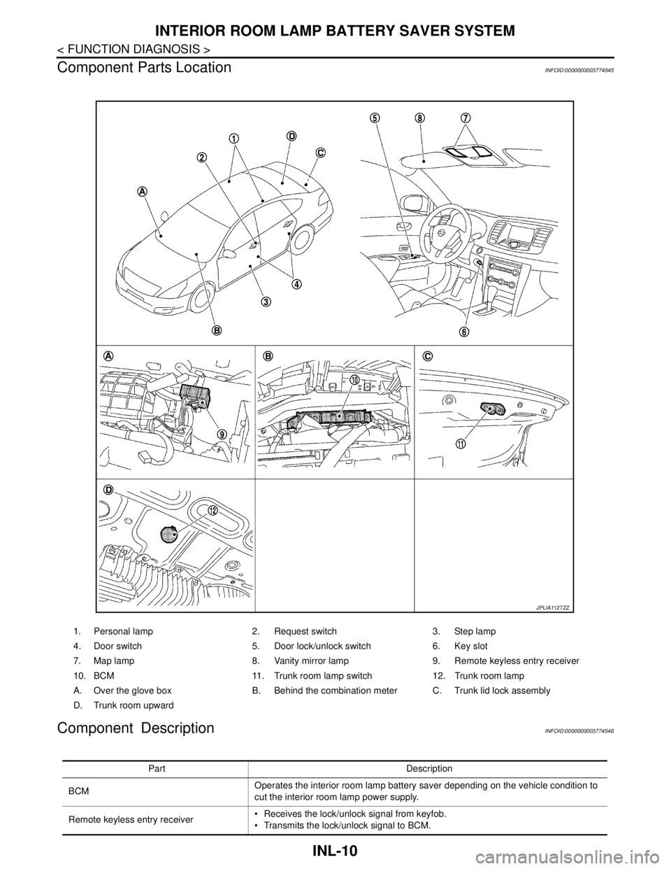
INTERIOR ROOM LAMP BATTERY SAVER SYSTEM
Component Parts Location
INFOID:0000000003774545
Component DescriptionINFOID:0000000003774546
1. Personal lamp 2. Request switch 3. Step lamp
4. Door switch 5. Door lock/unlock switch 6. Key slot
7. Map lamp 8. Vanity mirror lamp 9. Remote keyless entry receiver
10. BCM 11. Trunk room lamp switch 12. Trunk room lamp
A. Over the glove box B. Behind the combination meter C. Trunk lid lock assembly
D. Trunk room upward
JPLIA1127ZZ
Part Description
BCMOperates the interior room lamp battery saver depending on the vehicle condition to
cut the interior room lamp power supply.
Remote keyless entry receiver Receives the lock/unlock signal from keyfob.
Transmits the lock/unlock signal to BCM.
Page 3631 of 5121

PWC-1
BODY EXTERIOR, DOORS, ROOF & VEHICLE SECURITY
C
D
E
F
G
H
I
J
L
M
SECTION PWC
A
B
PWC
N
O
P
CONTENTS
POWER WINDOW CONTROL SYSTEM
BASIC INSPECTION ....................................4
DIAGNOSIS AND REPAIR WORKFLOW ..........4
WorkFlow ..................................................................4
INSPECTION AND ADJUSTMENT .....................5
ADDITIONAL SERVICE WHEN REMOVING BAT-
TERY NEGATIVE TERMINAL .....................................
5
ADDITIONAL SERVICE WHEN REMOVING
BATTERY NEGATIVE TERMINAL : Description ......
5
ADDITIONAL SERVICE WHEN REMOVING
BATTERY NEGATIVE TERMINAL : Special Re-
pair Requirement .......................................................
5
ADDITIONAL SERVICE WHEN REPLACING
CONTROL UNIT ..........................................................
5
ADDITIONAL SERVICE WHEN REPLACING
CONTROL UNIT : Description ..................................
5
ADDITIONAL SERVICE WHEN REPLACING
CONTROL UNIT : Special Repair Requirement .......
6
FUNCTION DIAGNOSIS ...............................7
POWER WINDOW SYSTEM ...............................7
System Diagram .......................................................7
System Description ...................................................7
Component Parts Location ......................................8
Component Description .............................................8
DIAGNOSIS SYSTEM (BCM) ............................10
COMMON ITEM .........................................................10
COMMON ITEM : CONSULT-III Function (BCM -
COMMON ITEM) .....................................................
10
RETAINED PWR .......................................................11
RETAINED PWR : CONSULT-III Function (BCM -
RETAINED PWR) ...................................................
11
COMPONENT DIAGNOSIS .........................12
POWER SUPPLY AND GROUND CIRCUIT ......12
BCM ...........................................................................12
BCM : Diagnosis Procedure ....................................12
POWER WINDOW MAIN SWITCH ............................12
POWER WINDOW MAIN SWITCH : Diagnosis
Procedure ................................................................
12
FRONT POWER WINDOW SWITCH (PASSEN-
GER SIDE) .................................................................
13
FRONT POWER WINDOW SWITCH (PASSEN-
GER SIDE) : Diagnosis Procedure ..........................
13
REAR POWER WINDOW SWITCH ...........................14
REAR POWER WINDOW SWITCH : Diagnosis
Procedure ................................................................
14
FRONT POWER WINDOW SWITCH (PAS-
SENGER SIDE) .................................................
16
Description ...............................................................16
Component Function Check ....................................16
Diagnosis Procedure ...............................................16
Component Inspection .............................................17
REAR POWER WINDOW SWITCH ..................18
Description ...............................................................18
Component Function Check ....................................18
Diagnosis Procedure ...............................................18
Component Inspection .............................................19
POWER WINDOW MOTOR ..............................20
DRIVER SIDE .............................................................20
DRIVER SIDE : Description .....................................20
DRIVER SIDE : Component Function Check ..........20
DRIVER SIDE : Diagnosis Procedure .....................20
DRIVER SIDE : Component Inspection ...................21
PASSENGER SIDE ....................................................21
PASSENGER SIDE : Description ............................21
PASSENGER SIDE : Component Function Check
....
21
PASSENGER SIDE : Diagnosis Procedure ............21
PASSENGER SIDE : Component Inspection ..........22
Page 3867 of 5121

SE-3
C
D
E
F
G
H
I
K
L
MA
B
SE
N
O
P REAR SEAT : Description .......................................
76
REAR SEAT : Diagnosis Procedure .......................76
ONLY SEAT CUSHION HEATER IS OPER-
ATED IN HI MODE OF HEATED SEAT .............
77
FRONT SEAT ............................................................77
FRONT SEAT : Description ....................................77
FRONT SEAT : Diagnosis Procedure .....................77
REAR SEAT ..............................................................77
REAR SEAT : Description .......................................77
REAR SEAT : Diagnosis Procedure .......................77
HEATED SEAT SWITCH INDICATOR DOES
NOT TURN ON ...................................................
78
FRONT SEAT ............................................................78
FRONT SEAT : Diagnosis Procedure .....................78
REAR SEAT ..............................................................78
REAR SEAT : Diagnosis Procedure .......................78
VENTILATION SEAT SWITCH INDICATOR
DOES NOT TURN ON ........................................
79
FRONT SEAT ............................................................79
FRONT SEAT : Diagnosis Procedure .....................79
REAR SEAT ..............................................................79
REAR SEAT : Diagnosis Procedure .......................79
SQUEAK AND RATTLE TROUBLE DIAG-
NOSES ...............................................................
80
Work Flow ...............................................................80
Inspection Procedure ..............................................82
Diagnostic Worksheet .............................................84
PRECAUTION ..............................................86
PRECAUTIONS ..................................................86
Precaution for Supplemental Restraint System
(SRS) "AIR BAG" and "SEAT BELT PRE-TEN-
SIONER" .................................................................
86
Precaution Necessary for Steering Wheel Rota-
tion after Battery Disconnect ...................................
86
Service Notice .........................................................86
Precaution for Work ................................................87
PREPARATION ...........................................88
PREPARATION ..................................................88
Commercial Service Tools .....................................88
ON-VEHICLE REPAIR .................................89
FRONT SEAT .....................................................89
Exploded View ........................................................89
Removal and Installation .........................................92
Disassembly and Assembly ....................................93
REAR SEAT .......................................................98
Exploded View ........................................................98
Removal and Installation .........................................99
Disassembly and Assembly ...................................100
POWER SEAT SWITCH .................................103
Exploded View .......................................................103
Removal and Installation .......................................103
HEATED SEAT SWITCH ................................104
FRONT SEAT ...........................................................104
FRONT SEAT : Exploded View .............................104
FRONT SEAT : Removal and Installation .............104
REAR SEAT .............................................................104
REAR SEAT : Exploded View ...............................105
REAR SEAT : Removal and Installation ................105
VENTILATION SEAT SWITCH .......................106
FRONT SEAT ...........................................................106
FRONT SEAT : Exploded View .............................106
FRONT SEAT : Removal and Installation .............106
REAR SEAT .............................................................106
REAR SEAT : Exploded View ...............................107
REAR SEAT : Removal and Installation ................107
WITHOUT VENTILATION SEAT
FUNCTION DIAGNOSIS ............................
108
POWER SEAT .................................................108
System Description ................................................108
Component Parts Location ....................................108
Component Description .........................................108
HEATED SEAT ...............................................110
System Description ................................................110
Component Parts Location ....................................110
Component Description .........................................110
COMPONENT DIAGNOSIS .......................111
POWER SEAT .................................................111
Wiring Diagram - POWER SEAT FOR DRIVER
SIDE - ....................................................................
111
Wiring Diagram - POWER SEAT FOR PASSEN-
GER SIDE - ...........................................................
114
HEATED SEAT ...............................................118
Wiring Diagram - HEATED SEAT - .......................118
SYMPTOM DIAGNOSIS ............................121
SQUEAK AND RATTLE TROUBLE DIAG-
NOSES ............................................................
121
Work Flow ..............................................................121
Inspection Procedure .............................................123
Diagnostic Worksheet ............................................125
PRECAUTION ............................................127
PRECAUTIONS ...............................................127
Page 3870 of 5121
![NISSAN TEANA 2008 Service Manual SE-6
< FUNCTION DIAGNOSIS >[WITH VENTILATION SEAT]
POWER SEAT
FUNCTION DIAGNOSIS
POWER SEAT
System DescriptionINFOID:0000000003809302
BCM can operate regardless of the ignition switch position, becaus NISSAN TEANA 2008 Service Manual SE-6
< FUNCTION DIAGNOSIS >[WITH VENTILATION SEAT]
POWER SEAT
FUNCTION DIAGNOSIS
POWER SEAT
System DescriptionINFOID:0000000003809302
BCM can operate regardless of the ignition switch position, becaus](/manual-img/5/57391/w960_57391-3869.png)
SE-6
< FUNCTION DIAGNOSIS >[WITH VENTILATION SEAT]
POWER SEAT
FUNCTION DIAGNOSIS
POWER SEAT
System DescriptionINFOID:0000000003809302
BCM can operate regardless of the ignition switch position, because battery power is supplied at all times to
power seat switch.
SLIDING OPERATION
While operating the sliding switch located in power seat switch, sliding motor operates and adjusts the front
and back position of the seat.
RECLINING OPERATION
While operating the reclining switch located in power seat switch, reclining motor operates and adjusts the for-
ward and backward position of the seatback.
LIFTING OPERATION
While operating the lifting switch located in power seat switch (driver side), lifting motor operates and adjusts
the up and down position of the seat cushion.
OTTOMAN OPERATION
While operating the ottoman switch located in power seat switch (passenger side), ottoman motor operates
and adjusts the up and down position of the ottoman.
Component Parts LocationINFOID:0000000003809303
1. Sliding switch and lifting switch (driv-
er side) B4142. Reclining switch (driver side) B414 3. Reclining switch (passenger side)
B446
4. Sliding switch and ottoman switch
B4465. Reclining motor (driver side) B415 6. Lifting motor (front) (driver side) B417
7. Sliding motor (driver side) B416 8. Lifting motor (rear) (driver side) B418 9. Sliding motor (passenger side) B437
JMJIA1838ZZ
Page 3972 of 5121
![NISSAN TEANA 2008 Service Manual SE-108
< FUNCTION DIAGNOSIS >[WITHOUT VENTILATION SEAT]
POWER SEAT
FUNCTION DIAGNOSIS
POWER SEAT
System DescriptionINFOID:0000000003839942
BCM can operate regardless of the ignition switch position, b NISSAN TEANA 2008 Service Manual SE-108
< FUNCTION DIAGNOSIS >[WITHOUT VENTILATION SEAT]
POWER SEAT
FUNCTION DIAGNOSIS
POWER SEAT
System DescriptionINFOID:0000000003839942
BCM can operate regardless of the ignition switch position, b](/manual-img/5/57391/w960_57391-3971.png)
SE-108
< FUNCTION DIAGNOSIS >[WITHOUT VENTILATION SEAT]
POWER SEAT
FUNCTION DIAGNOSIS
POWER SEAT
System DescriptionINFOID:0000000003839942
BCM can operate regardless of the ignition switch position, because battery power is supplied at all times to
power seat switch.
SLIDING OPERATION
While operating the sliding switch located in power seat switch, sliding motor operates and adjusts the front
and back position of the seat.
RECLINING OPERATION
While operating the reclining switch located in power seat switch, reclining motor operates and adjusts the for-
ward and backward position of the seatback.
LIFTING OPERATION
While operating the lifting switch located in power seat switch (driver side), lifting motor operates and adjusts
the up and down position of the seat cushion.
Component Parts LocationINFOID:0000000003839943
Component DescriptionINFOID:0000000003839944
1. Sliding switch and lifting switch (driv-
er side) B4142. Reclining switch (driver side) B4143. Reclining motor (driver side) B415
4. Lifting motor (front) (driver side)
B4175. Sliding motor (driver side) B416 6. Lifting motor (rear) (driver side) B418
A. View with seat cushion pad and seat-
back pad are removed.B. Backside of seat cushion
(driver side)
JMJIA1948ZZ
Item Function
BCM Supplies at all times the power received from battery to power seat switch
Power seat switch
(driver side)Built-in reclining switch, sliding switch and lifting switch, controls the power supplied to each motor
Power seat switch
(passenger side)Built-in reclining switch, sliding switch, controls the power supplied to each motor
Reclining motorWith the power supplied from power seat switch, operates forward and backward movement of
seatback
Page 4024 of 5121
![NISSAN TEANA 2008 Service Manual NISSAN VEHICLE IMMOBILIZER SYSTEM-NATS
SEC-15
< FUNCTION DIAGNOSIS >[INTELLIGENT KEY SYSTEM]
C
D
E
F
G
H
I
J
L
MA
B
SEC
N
O
P
The security indicator lamp always blinks when the ignition switch is in NISSAN TEANA 2008 Service Manual NISSAN VEHICLE IMMOBILIZER SYSTEM-NATS
SEC-15
< FUNCTION DIAGNOSIS >[INTELLIGENT KEY SYSTEM]
C
D
E
F
G
H
I
J
L
MA
B
SEC
N
O
P
The security indicator lamp always blinks when the ignition switch is in](/manual-img/5/57391/w960_57391-4023.png)
NISSAN VEHICLE IMMOBILIZER SYSTEM-NATS
SEC-15
< FUNCTION DIAGNOSIS >[INTELLIGENT KEY SYSTEM]
C
D
E
F
G
H
I
J
L
MA
B
SEC
N
O
P
The security indicator lamp always blinks when the ignition switch is in the LOCK and ACC position.
NOTE:
Because security indicator lamp is highly efficient, the battery is barely affected.
Component Parts LocationINFOID:0000000003814908
1. BCM M118, M119, M121, M122, M123 2. TCM F23 3. IPDM E/R E10, E11, F12
4. ECM E16 5. Push-button ignition switch M101 6. Key slot M99
7. Combination meter (key warning lamp)
M348. Combination meter (security indicator
lamp) M349. Horn (high) E340, E341
10. Horn (low) E342, E343 11. Control device (detention switch) M57 12. Stop lamp switch E115
13. Remote keyless entry receiver M78
A. Behind the combination meter B. Engine room (LH) C. View with the center console as-
sembly removed
D. Behind the instrument lower panel LH E. Behind the instrument lower panel RH
JMKIA2349ZZ