2008 NISSAN TEANA tire pressure
[x] Cancel search: tire pressurePage 1913 of 5121
EM-38
< ON-VEHICLE REPAIR >
OIL PAN AND OIL STRAINER
OIL PAN AND OIL STRAINER
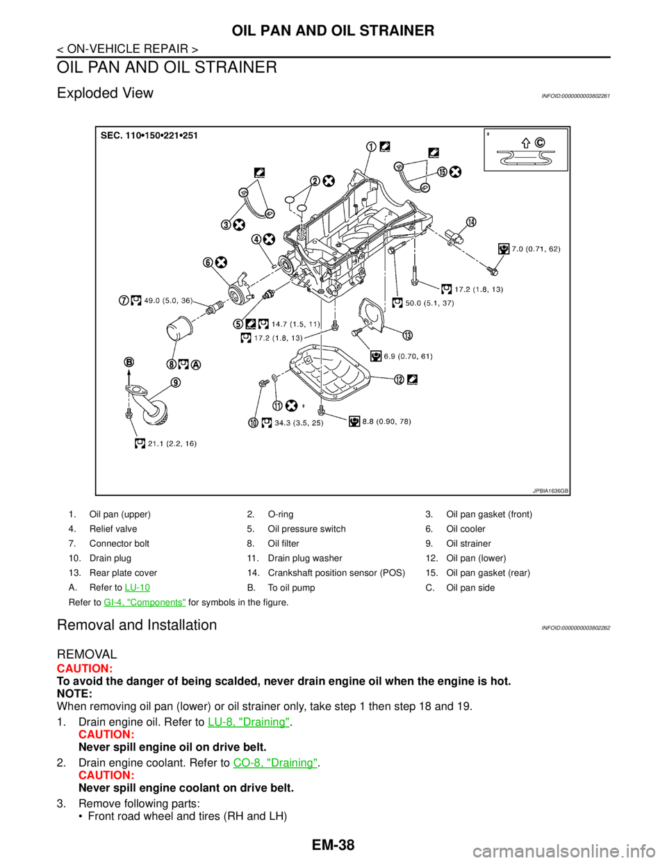
Exploded ViewINFOID:0000000003802261
Removal and InstallationINFOID:0000000003802262
REMOVAL
CAUTION:
To avoid the danger of being scalded, never drain engine oil when the engine is hot.
NOTE:
When removing oil pan (lower) or oil strainer only, take step 1 then step 18 and 19.
1. Drain engine oil. Refer to LU-8, "
Draining".
CAUTION:
Never spill engine oil on drive belt.
2. Drain engine coolant. Refer to CO-8, "
Draining".
CAUTION:
Never spill engine coolant on drive belt.
3. Remove following parts:
Front road wheel and tires (RH and LH)
1. Oil pan (upper) 2. O-ring 3. Oil pan gasket (front)
4. Relief valve 5. Oil pressure switch 6. Oil cooler
7. Connector bolt 8. Oil filter 9. Oil strainer
10. Drain plug 11. Drain plug washer 12. Oil pan (lower)
13. Rear plate cover 14. Crankshaft position sensor (POS) 15. Oil pan gasket (rear)
A. Refer to LU-10
B. To oil pump C. Oil pan side
Refer to GI-4, "
Components" for symbols in the figure.
JPBIA1636GB
Page 1943 of 5121
EM-68
< REMOVAL AND INSTALLATION >
ENGINE ASSEMBLY
Place chocks at front and back of rear wheels.
For engines not equipped with engine slingers, attach proper slingers and bolts described in PARTS
CATALOG.
CAUTION:
Always be careful to work safely, avoid forceful or uninstructed operations.
Never start working until exhaust system and engine coolant are cool enough.
If items or work required are not covered by the engine section, refer to the applicable sections.
Always use the support point specified for lifting.
Use either 2-pole lift type or separate type lift as best you can. If board-on type is used for unavoid-
able reasons, support at the rear axle jacking point with transmission jack or similar tool before
starting work, in preparation for the backward shift of center of gravity.
For supporting points for lifting and jacking point at rear axle, refer to GI-30, "
Garage Jack and
Safety Stand and 2-Pole Lift".
REMOVAL
Outline
At first, remove the engine and the transaxle assembly with front suspension member downward. Then sepa-
rate the engine and the transaxle.
Preparation
1. Release fuel pressure. Refer to EC-411, "Inspection".
2. Drain engine coolant. Refer to CO-8, "
Draining".
CAUTION:
Perform this step when the engine is cold.
Never spill engine coolant on drive belt.
3. Remove the following parts:
Engine cover: Refer to EM-24, "
Exploded View".
Front road wheel and tires
Splash guards (RH and LH): Refer to EXT-22, "
FENDER PROTECTOR : Exploded View".
Air duct (inlet), air cleaner cases (upper and lower) with mass air flow sensor and air duct assembly:
Refer to EM-26, "
Exploded View".
Battery and battery tray: Refer to PG-109, "
Removal and Installation".
Drive belt: Refer to EM-12, "
Removal and Installation".
Reservoir tank of radiator. Refer to CO-13, "
Exploded View".
Front wiper arm: Refer to WW-105, "
Exploded View".
4. Disconnect engine room harness at the TCM, ECM and other sides.
CAUTION:
To keep clean harness connector and avoid damage and foreign materials, cover them completely
with plastic bags or something similar.
5. Remove battery bracket with ECM and TCM.
6. Remove extension cowl top. Refer to EXT-20, "
Exploded View".
Engine Room
1. Disconnect heater hoses. Refer to CO-25, "Exploded View".
Install plug to avoid leakage of engine coolant.
2. Remove EVAP hose. Refer to EM-28, "
Exploded View".
3. Disconnect fuel feed hose quick connector at fuel tube side. Refer to EM-44, "
Exploded View".
Install plug to avoid leakage of fuel.
4. Disconnect transaxle shift control cable at transaxle side. Refer to TM-319, "
Exploded View" (VQ25DE) or
TM-157, "
Exploded View" (VQ35DE).
5. Disconnect brake booster vacuum hose at engine side. Refer to EM-28, "
Exploded View".
6. Disconnect ground cable.
7. Disconnect A/C compressor piping at A/C compressor side. Refer to HA-36, "
Exploded View".
8. Disconnect suction hoses of power steering oil pump at reservoir tank side. Refer to ST-34, "
Exploded
View".
Install plug to avoid leakage of power steering fluid.
9. Disconnect CVT fluid cooler hoses from radiator. Refer to CO-13, "
Exploded View".
Page 2202 of 5121
![NISSAN TEANA 2008 Service Manual HEADLAMP AIMING ADJUSTMENT
EXL-173
< ON-VEHICLE MAINTENANCE >[XENON TYPE]
C
D
E
F
G
H
I
J
K
MA
B
EXL
N
O
P
ON-VEHICLE MAINTENANCE
HEADLAMP AIMING ADJUSTMENT
DescriptionINFOID:0000000003774534
PREPARAT](/manual-img/5/57391/w960_57391-2201.png "NISSAN TEANA 2008 Service Manual HEADLAMP AIMING ADJUSTMENT
EXL-173
< ON-VEHICLE MAINTENANCE >[XENON TYPE]
C
D
E
F
G
H
I
J
K
MA
B
EXL
N
O
P
ON-VEHICLE MAINTENANCE
HEADLAMP AIMING ADJUSTMENT
DescriptionINFOID:0000000003774534
PREPARAT")
HEADLAMP AIMING ADJUSTMENT
EXL-173
< ON-VEHICLE MAINTENANCE >[XENON TYPE]
C
D
E
F
G
H
I
J
K
MA
B
EXL
N
O
P
ON-VEHICLE MAINTENANCE
HEADLAMP AIMING ADJUSTMENT
DescriptionINFOID:0000000003774534
PREPARATION BEFORE ADJUSTING
NOTE:
For details, refer to the regulations in your own country.
Perform aiming if the vehicle front body has been repaired and/or the headlamp assembly has been
replaced.
Before performing aiming adjustment, check the following. Adjust the tire pressure to the specification.
Fill with fuel, engine coolant and each oil.
Maintain the unloaded vehicle condition. (Remove luggage from the passenger compartment and the trunk
room.)
NOTE:
Do not remove the temporary tire, jack and on-vehicle tool.
Wipe out dirt on the headlamp.
CAUTION:
Never use organic solvent (thinner, gasoline etc.)
Ride alone on the driver seat.
AIMING ADJUSTMENT SCREW
JPLIA1085ZZ
Page 2207 of 5121
![NISSAN TEANA 2008 Service Manual EXL-178
< ON-VEHICLE MAINTENANCE >[XENON TYPE]
FRONT FOG LAMP AIMING ADJUSTMENT
FRONT FOG LAMP AIMING ADJUSTMENT
DescriptionINFOID:0000000003773617
PREPARATION BEFORE ADJUSTING
NOTE:
For details, re](/manual-img/5/57391/w960_57391-2206.png "NISSAN TEANA 2008 Service Manual EXL-178
< ON-VEHICLE MAINTENANCE >[XENON TYPE]
FRONT FOG LAMP AIMING ADJUSTMENT
FRONT FOG LAMP AIMING ADJUSTMENT
DescriptionINFOID:0000000003773617
PREPARATION BEFORE ADJUSTING
NOTE:
For details, re")
EXL-178
< ON-VEHICLE MAINTENANCE >[XENON TYPE]
FRONT FOG LAMP AIMING ADJUSTMENT
FRONT FOG LAMP AIMING ADJUSTMENT
DescriptionINFOID:0000000003773617
PREPARATION BEFORE ADJUSTING
NOTE:
For details, refer to the regulations in your own country.
Before performing aiming adjustment, check the following.
Adjust the tire pressure to the specification.
Fill with fuel, engine coolant and each oil.
Maintain the unloaded vehicle condition. (Remove luggage from the passenger compartment and the lug-
gage room.)
NOTE:
Do not remove the temporary tire, jack and on-vehicle tool.
Wipe out dirt on the headlamp.
CAUTION:
Never use organic solvent (thinner, gasoline etc.)
Ride alone on the driver seat.
AIMING ADJUSTMENT SCREW
Turn the aiming adjusting screw for adjustment.
For the position and direction of the adjusting screw, refer to the
figure.
NOTE:
A screwdriver or hexagonal wrench [6 mm (0.24 in)] can be used
for adjustment.
Aiming Adjustment ProcedureINFOID:0000000003773618
1. Place the screen.
NOTE:
Stop the vehicle facing the wall.
Place the board on a plain road vertically.
2. Face the vehicle with the screen. Maintain 10 m (32.8 ft) between the front fog lamp center and the
screen.
3. Start the engine. Illuminate the front fog lamp.
CAUTION:
Never cover the lens surface with a tape etc. The lens is made of resin.
NOTE:
Shut off the headlamp light with the board to prevent from illuminating the adjustment screen.
4. Adjust the cutoff line height (A) with the aiming adjustment screw so that the distance (X) between the hor-
izontal center line of front fog lamp (H) and (A) becomes 200 mm (7.87 in).
Front fog lamp light distribution on the screen
A: UP
B: DOWN
JPLIA1086ZZ
JPLIA0008ZZ
Page 2365 of 5121
![NISSAN TEANA 2008 Service Manual EXL-336
< ON-VEHICLE MAINTENANCE >[HALOGEN TYPE]
HEADLAMP AIMING ADJUSTMENT
ON-VEHICLE MAINTENANCE
HEADLAMP AIMING ADJUSTMENT
DescriptionINFOID:0000000003829238
PREPARATION BEFORE ADJUSTING
NOTE:
Fo](/manual-img/5/57391/w960_57391-2364.png "NISSAN TEANA 2008 Service Manual EXL-336
< ON-VEHICLE MAINTENANCE >[HALOGEN TYPE]
HEADLAMP AIMING ADJUSTMENT
ON-VEHICLE MAINTENANCE
HEADLAMP AIMING ADJUSTMENT
DescriptionINFOID:0000000003829238
PREPARATION BEFORE ADJUSTING
NOTE:
Fo")
EXL-336
< ON-VEHICLE MAINTENANCE >[HALOGEN TYPE]
HEADLAMP AIMING ADJUSTMENT
ON-VEHICLE MAINTENANCE
HEADLAMP AIMING ADJUSTMENT
DescriptionINFOID:0000000003829238
PREPARATION BEFORE ADJUSTING
NOTE:
For details, refer to the regulations in your own country.
Perform aiming if the vehicle front body has been repaired and/or the headlamp assembly has been
replaced.
Before performing aiming adjustment, check the following. Adjust the tire pressure to the specification.
Fill with fuel, engine coolant and each oil.
Maintain the unloaded vehicle condition. (Remove luggage from the passenger compartment and the trunk
room.)
NOTE:
Do not remove the temporary tire, jack and on-vehicle tool.
Wipe out dirt on the headlamp.
CAUTION:
Never use organic solvent (thinner, gasoline etc.)
Ride alone on the driver seat.
Headlamp aiming switch sets to “0”.
AIMING ADJUSTMENT SCREW
JPLIA1104ZZ
Page 2370 of 5121
![NISSAN TEANA 2008 Service Manual FRONT FOG LAMP AIMING ADJUSTMENT
EXL-341
< ON-VEHICLE MAINTENANCE >[HALOGEN TYPE]
C
D
E
F
G
H
I
J
K
MA
B
EXL
N
O
P
FRONT FOG LAMP AIMING ADJUSTMENT
DescriptionINFOID:0000000003894358
PREPARATION BEFOR](/manual-img/5/57391/w960_57391-2369.png "NISSAN TEANA 2008 Service Manual FRONT FOG LAMP AIMING ADJUSTMENT
EXL-341
< ON-VEHICLE MAINTENANCE >[HALOGEN TYPE]
C
D
E
F
G
H
I
J
K
MA
B
EXL
N
O
P
FRONT FOG LAMP AIMING ADJUSTMENT
DescriptionINFOID:0000000003894358
PREPARATION BEFOR")
FRONT FOG LAMP AIMING ADJUSTMENT
EXL-341
< ON-VEHICLE MAINTENANCE >[HALOGEN TYPE]
C
D
E
F
G
H
I
J
K
MA
B
EXL
N
O
P
FRONT FOG LAMP AIMING ADJUSTMENT
DescriptionINFOID:0000000003894358
PREPARATION BEFORE ADJUSTING
NOTE:
For details, refer to the regulations in your own country.
Before performing aiming adjustment, check the following.
Adjust the tire pressure to the specification.
Fill with fuel, engine coolant and each oil.
Maintain the unloaded vehicle condition. (Remove luggage from the passenger compartment and the lug-
gage room.)
NOTE:
Do not remove the temporary tire, jack and on-vehicle tool.
Wipe out dirt on the headlamp.
CAUTION:
Never use organic solvent (thinner, gasoline etc.)
Ride alone on the driver seat.
AIMING ADJUSTMENT SCREW
Turn the aiming adjusting screw for adjustment.
For the position and direction of the adjusting screw, refer to the
figure.
NOTE:
A screwdriver or hexagonal wrench [6 mm (0.24 in)] can be used
for adjustment.
Aiming Adjustment ProcedureINFOID:0000000003894359
1. Place the screen.
NOTE:
Stop the vehicle facing the wall.
Place the board on a plain road vertically.
2. Face the vehicle with the screen. Maintain 10 m (32.8 ft) between the front fog lamp center and the
screen.
3. Start the engine. Illuminate the front fog lamp.
CAUTION:
Never cover the lens surface with a tape etc. The lens is made of resin.
NOTE:
Shut off the headlamp light with the board to prevent from illuminating the adjustment screen.
4. Adjust the cutoff line height (A) with the aiming adjustment screw so that the distance (X) between the hor-
izontal center line of front fog lamp (H) and (A) becomes 200 mm (7.87 in).
Front fog lamp light distribution on the screen
A: UP
B: DOWN
JPLIA1086ZZ
JPLIA0008ZZ
Page 2481 of 5121
WHEEL ALIGNMENT
FSU-7
< ON-VEHICLE MAINTENANCE >
C
D
F
G
H
I
J
K
L
MA
B
FSU
N
O
P
WHEEL ALIGNMENT
Wheel Alignment InspectionINFOID:0000000003812473
INSPECTION
Description
CAUTION:
Camber, caster, kingpin inclination angles cannot be adjusted.
If camber, caster, or kingpin inclination angle exceeds the standard value, check front suspension
parts for wear and damage. Replace suspect parts if a malfunction is detected.
Kingpin inclination angle is reference value, no inspection is required.
Measure wheel alignment under unladen conditions.
NOTE:
“Unladen conditions” means that fuel, engine coolant, and lubricant are full. Spare tire, jack, hand tools and
mats are in designated positions.
Preliminary Check
Check the following:
Tires for improper air pressure and wear
Road wheels for runout: Refer to WT-2, "
Inspection".
Wheel bearing axial end play: Refer to FA X - 6 , "
Inspection".
Transverse link ball joint axial end play: Refer to FSU-11, "
Inspection".
Strut operation.
Each mounting part of axle and suspension for looseness and deformation
Each of suspension member and transverse link for cracks, deformation and other damage
Vehicle height (posture)
CAMBER, CASTER, AND KINGPIN INCLINATION ANGLES
Camber, caster, kingpin inclination angles cannot be adjusted.
Before inspection, mount front wheels onto turning radius gauge. Mount rear wheels onto a stand at the
same height so that vehicle remains horizontal.
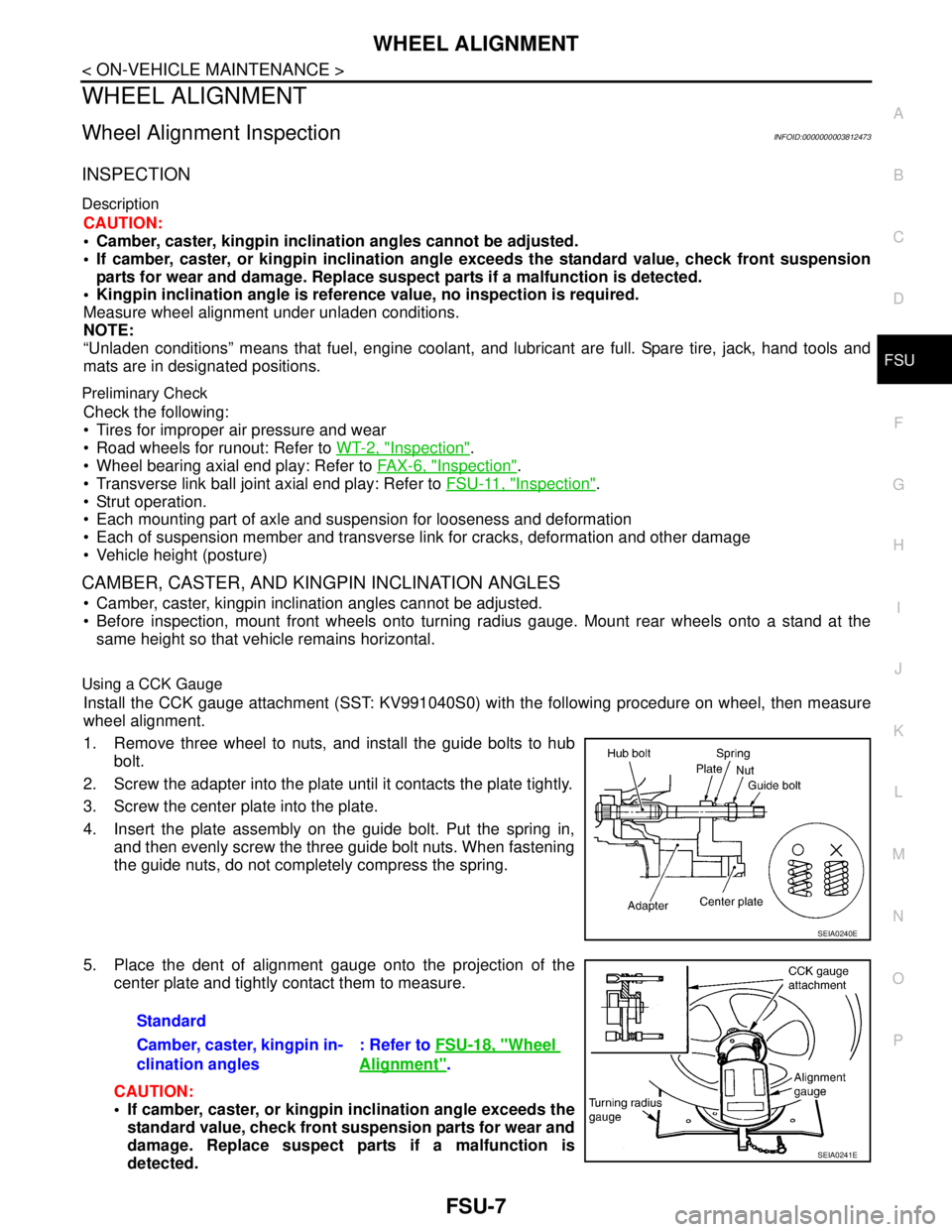
Using a CCK Gauge
Install the CCK gauge attachment (SST: KV991040S0) with the following procedure on wheel, then measure
wheel alignment.
1. Remove three wheel to nuts, and install the guide bolts to hub
bolt.
2. Screw the adapter into the plate until it contacts the plate tightly.
3. Screw the center plate into the plate.
4. Insert the plate assembly on the guide bolt. Put the spring in,
and then evenly screw the three guide bolt nuts. When fastening
the guide nuts, do not completely compress the spring.
5. Place the dent of alignment gauge onto the projection of the
center plate and tightly contact them to measure.
CAUTION:
If camber, caster, or kingpin inclination angle exceeds the
standard value, check front suspension parts for wear and
damage. Replace suspect parts if a malfunction is
detected.
SEIA0240E
Standard
Camber, caster, kingpin in-
clination angles: Refer to FSU-18, "
Wheel
Alignment".
SEIA0241E
Page 2490 of 5121
FSU-16
< REMOVAL AND INSTALLATION >
FRONT SUSPENSION MEMBER
REMOVAL AND INSTALLATION
FRONT SUSPENSION MEMBER
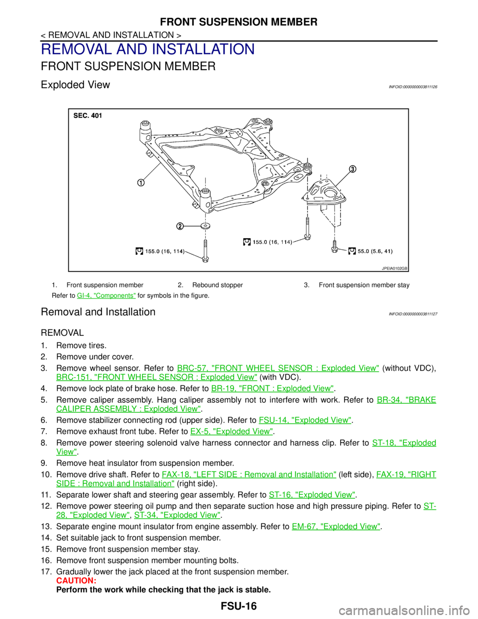
Exploded ViewINFOID:0000000003811126
Removal and InstallationINFOID:0000000003811127
REMOVAL
1. Remove tires.
2. Remove under cover.
3. Remove wheel sensor. Refer to BRC-57, "
FRONT WHEEL SENSOR : Exploded View" (without VDC),
BRC-151, "
FRONT WHEEL SENSOR : Exploded View" (with VDC).
4. Remove lock plate of brake hose. Refer to BR-19, "
FRONT : Exploded View".
5. Remove caliper assembly. Hang caliper assembly not to interfere with work. Refer to BR-34, "
BRAKE
CALIPER ASSEMBLY : Exploded View".
6. Remove stabilizer connecting rod (upper side). Refer to FSU-14, "
Exploded View".
7. Remove exhaust front tube. Refer to EX-5, "
Exploded View".
8. Remove power steering solenoid valve harness connector and harness clip. Refer to ST-18, "
Exploded
View".
9. Remove heat insulator from suspension member.
10. Remove drive shaft. Refer to FAX-18, "
LEFT SIDE : Removal and Installation" (left side), FAX-19, "RIGHT
SIDE : Removal and Installation" (right side).
11. Separate lower shaft and steering gear assembly. Refer to ST-16, "
Exploded View".
12. Remove power steering oil pump and then separate suction hose and high pressure piping. Refer to ST-
28, "Exploded View", ST-34, "Exploded View".
13. Separate engine mount insulator from engine assembly. Refer to EM-67, "
Exploded View".
14. Set suitable jack to front suspension member.
15. Remove front suspension member stay.
16. Remove front suspension member mounting bolts.
17. Gradually lower the jack placed at the front suspension member.
CAUTION:
Perform the work while checking that the jack is stable.
1. Front suspension member 2. Rebound stopper 3. Front suspension member stay
Refer to GI-4, "
Components" for symbols in the figure.
JPEIA0102GB