2008 NISSAN TEANA wheel bolts
[x] Cancel search: wheel boltsPage 1944 of 5121
ENGINE ASSEMBLY
EM-69
< REMOVAL AND INSTALLATION >
C
D
E
F
G
H
I
J
K
L
MA
EM
N
P O
10. Remove starter motor. Refer to STR-15, "VQ25DE : Exploded View" (VQ25DE) or STR-20, "VQ35DE :
Exploded View" (VQ35DE).
Vehicle Underbody
1. Remove front drive shafts (RH and LH). Refer to FAX-16, "Exploded View".
2. Remove exhaust front tube. Refer to EX-5, "
Exploded View".
3. Remove heat insulator.
4. Disconnect steering lower joint at power steering gear assembly side, and release steering lower shaft.
Refer to ST-16, "
Exploded View".
5. Disconnect front stabilizer connecting rod. Refer to FSU-14, "
Exploded View".
6. Remove strut assembly and steering knuckle fixing nuts and bolts. Refer to FSU-9, "
Exploded View" and
FA X - 8 , "
Exploded View".
7. Remove front wheel sensor (RH and LH) for ABS from steering knuckle. Refer to BRC-57, "
FRONT
WHEEL SENSOR : Exploded View".
8. Remove front brake caliper assembly with piping connected, and temporarily secure it to aside for vehicle
side. Refer to BR-34, "
BRAKE CALIPER ASSEMBLY : Exploded View".
9. Disconnect power steering piping at a point between vehicle and engine. Refer to ST-34, "
Exploded
View".
Install plug to avoid leakage of power steering fluid.
10. Remove rear plate cover from oil pan (upper). Then remove bolts fixing drive plate to torque converter.
Refer to EM-38, "
Exploded View" and TM-332, "Removal and Installation" (VQ25DE) or TM-168,
"Removal and Installation" (VQ35DE).
11. Remove transaxle joint bolts which pierce at oil pan (upper) lower rear side. Refer to EM-38, "
Exploded
View".
12. Remove crankshaft position sensor (POS). Refer to EM-38, "
Exploded View".
CAUTION:
Handle carefully to avoid dropping and shocks.
Never disassemble.
Never allow metal powder to adhere to magnetic part at sensor tip.
Never place sensors in a location where they are exposed to magnetism.
Removal
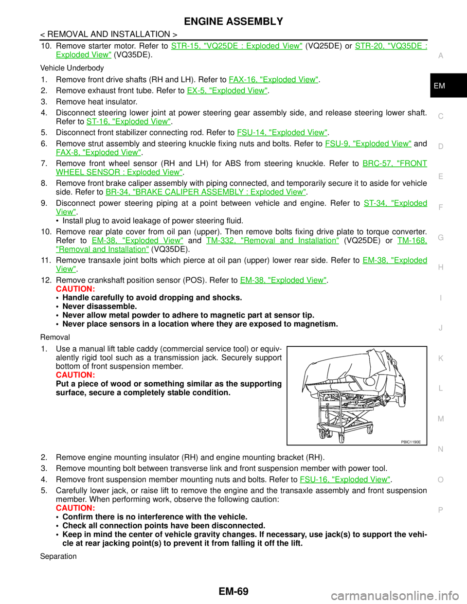
1. Use a manual lift table caddy (commercial service tool) or equiv-
alently rigid tool such as a transmission jack. Securely support
bottom of front suspension member.
CAUTION:
Put a piece of wood or something similar as the supporting
surface, secure a completely stable condition.
2. Remove engine mounting insulator (RH) and engine mounting bracket (RH).
3. Remove mounting bolt between transverse link and front suspension member with power tool.
4. Remove front suspension member mounting nuts and bolts. Refer to FSU-16, "
Exploded View".
5. Carefully lower jack, or raise lift to remove the engine and the transaxle assembly and front suspension
member. When performing work, observe the following caution:
CAUTION:
Confirm there is no interference with the vehicle.
Check all connection points have been disconnected.
Keep in mind the center of vehicle gravity changes. If necessary, use jack(s) to support the vehi-
cle at rear jacking point(s) to prevent it from falling it off the lift.
Separation
PBIC1190E
Page 2447 of 5121
FRONT DRIVE SHAFT
FAX-19
< ON-VEHICLE REPAIR >
C
E
F
G
H
I
J
K
L
MA
B
FA X
N
O
P
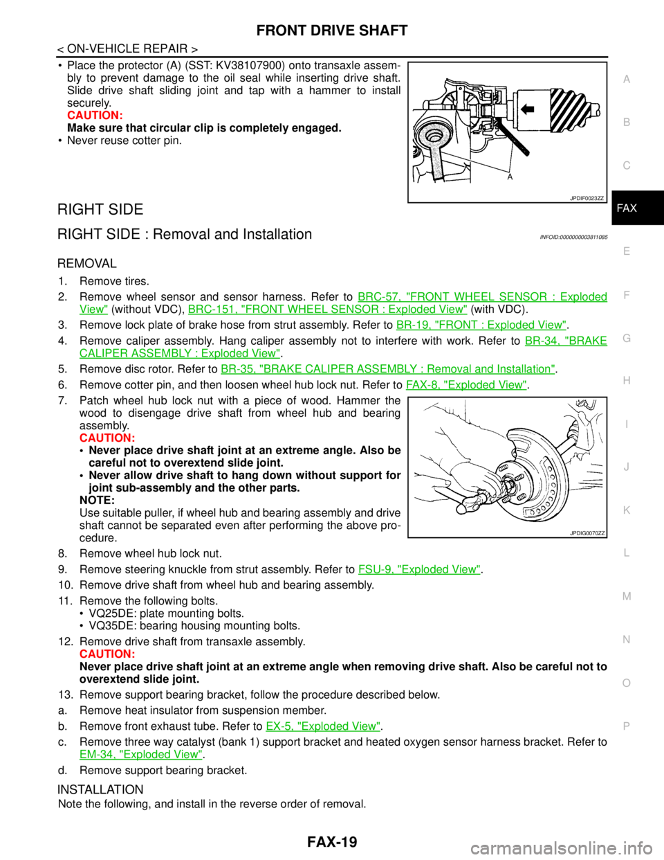
Place the protector (A) (SST: KV38107900) onto transaxle assem-
bly to prevent damage to the oil seal while inserting drive shaft.
Slide drive shaft sliding joint and tap with a hammer to install
securely.
CAUTION:
Make sure that circular clip is completely engaged.
Never reuse cotter pin.
RIGHT SIDE
RIGHT SIDE : Removal and InstallationINFOID:0000000003811085
REMOVAL
1. Remove tires.
2. Remove wheel sensor and sensor harness. Refer to BRC-57, "
FRONT WHEEL SENSOR : Exploded
View" (without VDC), BRC-151, "FRONT WHEEL SENSOR : Exploded View" (with VDC).
3. Remove lock plate of brake hose from strut assembly. Refer to BR-19, "
FRONT : Exploded View".
4. Remove caliper assembly. Hang caliper assembly not to interfere with work. Refer to BR-34, "
BRAKE
CALIPER ASSEMBLY : Exploded View".
5. Remove disc rotor. Refer to BR-35, "
BRAKE CALIPER ASSEMBLY : Removal and Installation".
6. Remove cotter pin, and then loosen wheel hub lock nut. Refer to FA X - 8 , "
Exploded View".
7. Patch wheel hub lock nut with a piece of wood. Hammer the
wood to disengage drive shaft from wheel hub and bearing
assembly.
CAUTION:
Never place drive shaft joint at an extreme angle. Also be
careful not to overextend slide joint.
Never allow drive shaft to hang down without support for
joint sub-assembly and the other parts.
NOTE:
Use suitable puller, if wheel hub and bearing assembly and drive
shaft cannot be separated even after performing the above pro-
cedure.
8. Remove wheel hub lock nut.
9. Remove steering knuckle from strut assembly. Refer to FSU-9, "
Exploded View".
10. Remove drive shaft from wheel hub and bearing assembly.
11. Remove the following bolts.
VQ25DE: plate mounting bolts.
VQ35DE: bearing housing mounting bolts.
12. Remove drive shaft from transaxle assembly.
CAUTION:
Never place drive shaft joint at an extreme angle when removing drive shaft. Also be careful not to
overextend slide joint.
13. Remove support bearing bracket, follow the procedure described below.
a. Remove heat insulator from suspension member.
b. Remove front exhaust tube. Refer to EX-5, "
Exploded View".
c. Remove three way catalyst (bank 1) support bracket and heated oxygen sensor harness bracket. Refer to
EM-34, "
Exploded View".
d. Remove support bearing bracket.
INSTALLATION
Note the following, and install in the reverse order of removal.
JPDIF0023ZZ
JPDIG0070ZZ
Page 2448 of 5121
FAX-20
< ON-VEHICLE REPAIR >
FRONT DRIVE SHAFT
Always replace differential side oil seal with new one when installing drive shaft. Refer to TM-162, "Exploded
View" (CVT: RE0F09B), TM-325, "Exploded View" (CVT: RE0F10A).
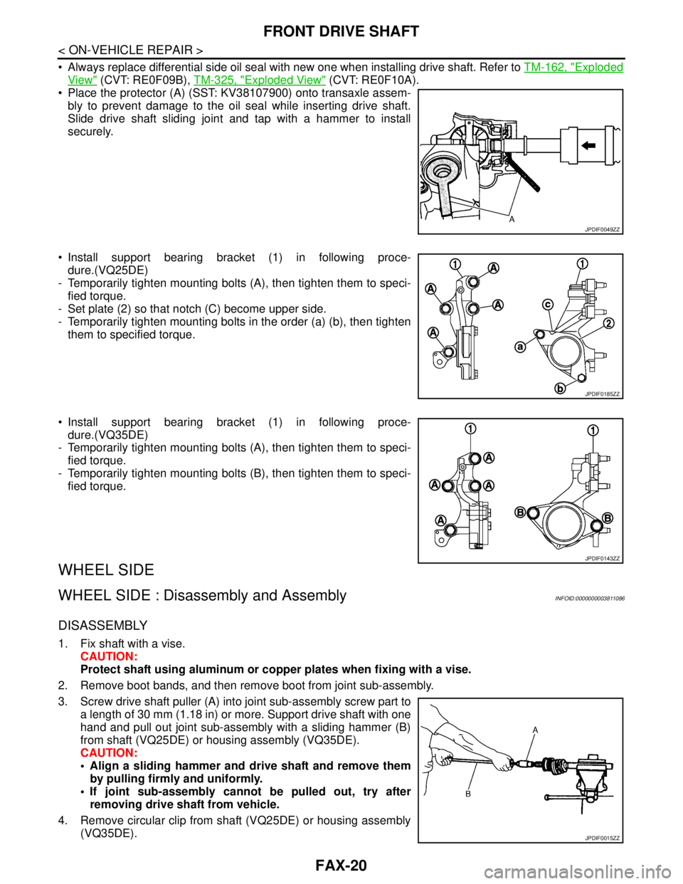
Place the protector (A) (SST: KV38107900) onto transaxle assem-
bly to prevent damage to the oil seal while inserting drive shaft.
Slide drive shaft sliding joint and tap with a hammer to install
securely.
Install support bearing bracket (1) in following proce-
dure.(VQ25DE)
- Temporarily tighten mounting bolts (A), then tighten them to speci-
fied torque.
- Set plate (2) so that notch (C) become upper side.
- Temporarily tighten mounting bolts in the order (a) (b), then tighten
them to specified torque.
Install support bearing bracket (1) in following proce-
dure.(VQ35DE)
- Temporarily tighten mounting bolts (A), then tighten them to speci-
fied torque.
- Temporarily tighten mounting bolts (B), then tighten them to speci-
fied torque.
WHEEL SIDE
WHEEL SIDE : Disassembly and AssemblyINFOID:0000000003811086
DISASSEMBLY
1. Fix shaft with a vise.
CAUTION:
Protect shaft using aluminum or copper plates when fixing with a vise.
2. Remove boot bands, and then remove boot from joint sub-assembly.
3. Screw drive shaft puller (A) into joint sub-assembly screw part to
a length of 30 mm (1.18 in) or more. Support drive shaft with one
hand and pull out joint sub-assembly with a sliding hammer (B)
from shaft (VQ25DE) or housing assembly (VQ35DE).
CAUTION:
Align a sliding hammer and drive shaft and remove them
by pulling firmly and uniformly.
If joint sub-assembly cannot be pulled out, try after
removing drive shaft from vehicle.
4. Remove circular clip from shaft (VQ25DE) or housing assembly
(VQ35DE).
JPDIF0049ZZ
JPDIF0185ZZ
JPDIF0143ZZ
JPDIF0015ZZ
Page 2481 of 5121
WHEEL ALIGNMENT
FSU-7
< ON-VEHICLE MAINTENANCE >
C
D
F
G
H
I
J
K
L
MA
B
FSU
N
O
P
WHEEL ALIGNMENT
Wheel Alignment InspectionINFOID:0000000003812473
INSPECTION
Description
CAUTION:
Camber, caster, kingpin inclination angles cannot be adjusted.
If camber, caster, or kingpin inclination angle exceeds the standard value, check front suspension
parts for wear and damage. Replace suspect parts if a malfunction is detected.
Kingpin inclination angle is reference value, no inspection is required.
Measure wheel alignment under unladen conditions.
NOTE:
“Unladen conditions” means that fuel, engine coolant, and lubricant are full. Spare tire, jack, hand tools and
mats are in designated positions.
Preliminary Check
Check the following:
Tires for improper air pressure and wear
Road wheels for runout: Refer to WT-2, "
Inspection".
Wheel bearing axial end play: Refer to FA X - 6 , "
Inspection".
Transverse link ball joint axial end play: Refer to FSU-11, "
Inspection".
Strut operation.
Each mounting part of axle and suspension for looseness and deformation
Each of suspension member and transverse link for cracks, deformation and other damage
Vehicle height (posture)
CAMBER, CASTER, AND KINGPIN INCLINATION ANGLES
Camber, caster, kingpin inclination angles cannot be adjusted.
Before inspection, mount front wheels onto turning radius gauge. Mount rear wheels onto a stand at the
same height so that vehicle remains horizontal.
Using a CCK Gauge
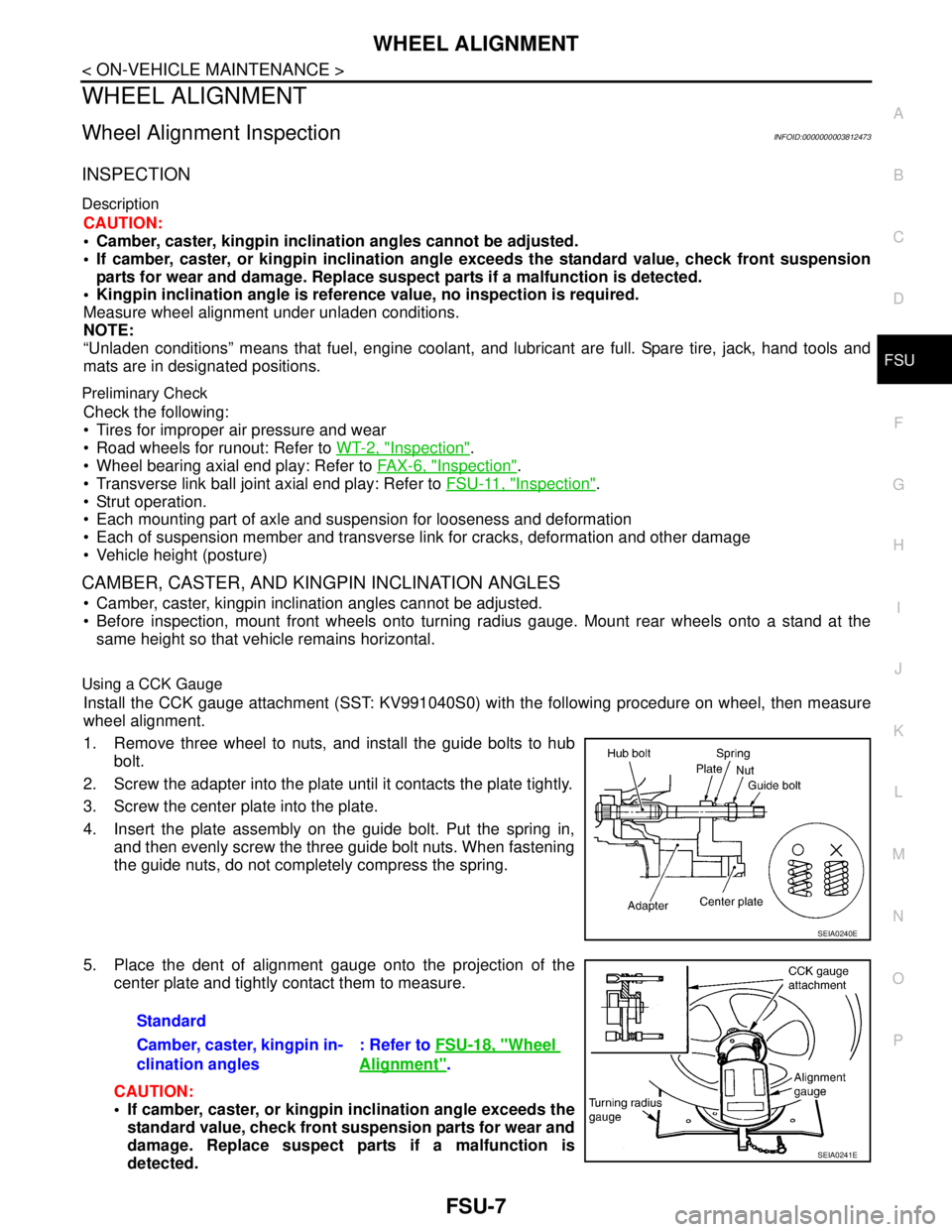
Install the CCK gauge attachment (SST: KV991040S0) with the following procedure on wheel, then measure
wheel alignment.
1. Remove three wheel to nuts, and install the guide bolts to hub
bolt.
2. Screw the adapter into the plate until it contacts the plate tightly.
3. Screw the center plate into the plate.
4. Insert the plate assembly on the guide bolt. Put the spring in,
and then evenly screw the three guide bolt nuts. When fastening
the guide nuts, do not completely compress the spring.
5. Place the dent of alignment gauge onto the projection of the
center plate and tightly contact them to measure.
CAUTION:
If camber, caster, or kingpin inclination angle exceeds the
standard value, check front suspension parts for wear and
damage. Replace suspect parts if a malfunction is
detected.
SEIA0240E
Standard
Camber, caster, kingpin in-
clination angles: Refer to FSU-18, "
Wheel
Alignment".
SEIA0241E
Page 2483 of 5121
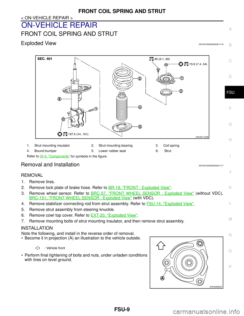
FRONT COIL SPRING AND STRUT
FSU-9
< ON-VEHICLE REPAIR >
C
D
F
G
H
I
J
K
L
MA
B
FSU
N
O
P
ON-VEHICLE REPAIR
FRONT COIL SPRING AND STRUT
Exploded ViewINFOID:000000000381111 6
Removal and InstallationINFOID:000000000381111 7
REMOVAL
1. Remove tires.
2. Remove lock plate of brake hose. Refer to BR-19, "
FRONT : Exploded View".
3. Remove wheel sensor. Refer to BRC-57, "
FRONT WHEEL SENSOR : Exploded View" (without VDC),
BRC-151, "
FRONT WHEEL SENSOR : Exploded View" (with VDC).
4. Remove stabilizer connecting rod from strut assembly. Refer to FSU-14, "
Exploded View".
5. Remove strut assembly from steering knuckle.
6. Remove cowl top cover. Refer to EXT-20, "
Exploded View".
7. Remove mounting bolts of strut mounting insulator, and then remove strut assembly.
INSTALLATION
Note the following, and install in the reverse order of removal.
Become it in projection (A) an illustration to the vehicle outside.
Perform final tightening of bolts and nuts, under unladen conditions
with tires on level ground.
1. Strut mounting insulator 2. Strut mounting bearing 3. Coil spring
4. Bound bumper 5. Lower rubber seat 6. Strut
Refer to GI-4, "
Components" for symbols in the figure.
JPEIA0112GB
: Vehicle front
JPEIA0094ZZ
Page 2486 of 5121
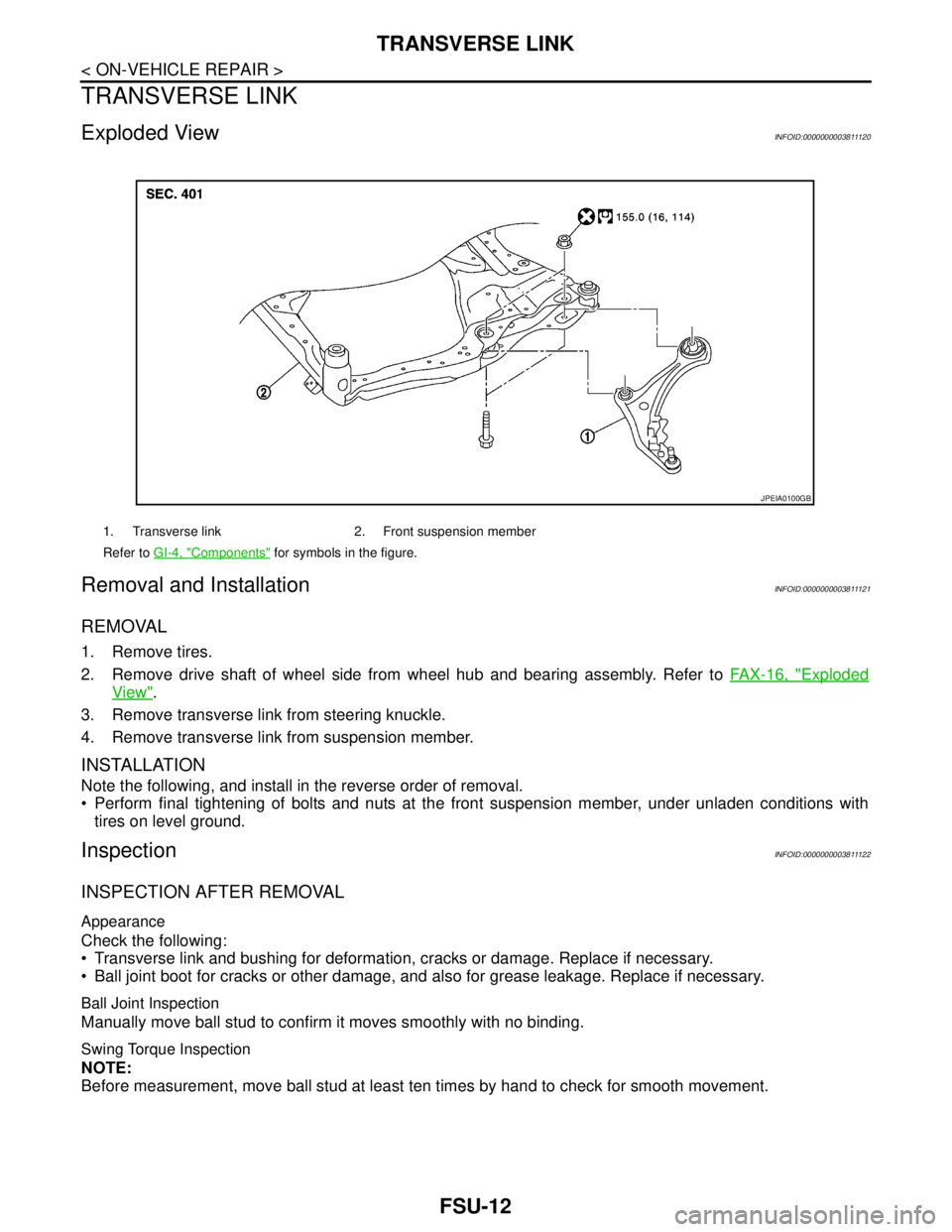
FSU-12
< ON-VEHICLE REPAIR >
TRANSVERSE LINK
TRANSVERSE LINK
Exploded ViewINFOID:0000000003811120
Removal and InstallationINFOID:0000000003811121
REMOVAL
1. Remove tires.
2. Remove drive shaft of wheel side from wheel hub and bearing assembly. Refer to FAX-16, "
Exploded
View".
3. Remove transverse link from steering knuckle.
4. Remove transverse link from suspension member.
INSTALLATION
Note the following, and install in the reverse order of removal.
Perform final tightening of bolts and nuts at the front suspension member, under unladen conditions with
tires on level ground.
InspectionINFOID:0000000003811122
INSPECTION AFTER REMOVAL
Appearance
Check the following:
Transverse link and bushing for deformation, cracks or damage. Replace if necessary.
Ball joint boot for cracks or other damage, and also for grease leakage. Replace if necessary.
Ball Joint Inspection
Manually move ball stud to confirm it moves smoothly with no binding.
Swing Torque Inspection
NOTE:
Before measurement, move ball stud at least ten times by hand to check for smooth movement.
1. Transverse link 2. Front suspension member
Refer to GI-4, "
Components" for symbols in the figure.
JPEIA0100GB
Page 2490 of 5121
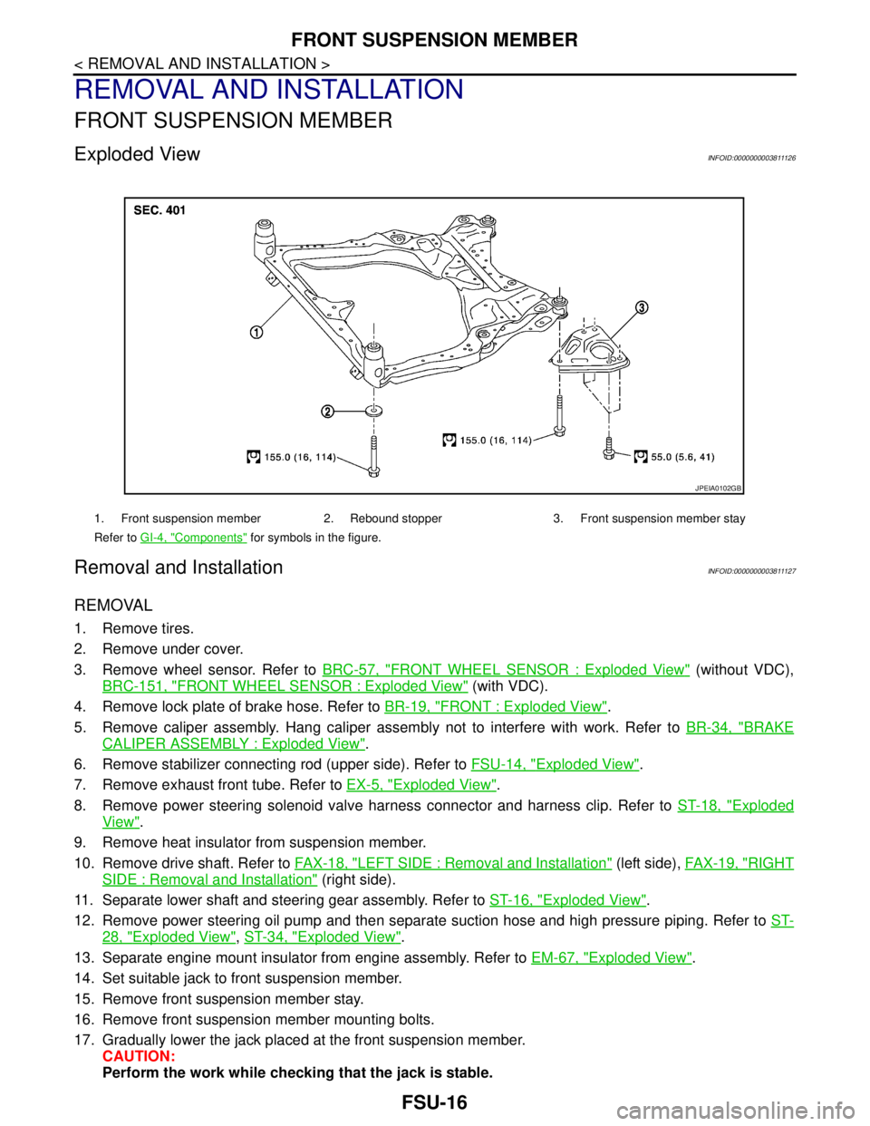
FSU-16
< REMOVAL AND INSTALLATION >
FRONT SUSPENSION MEMBER
REMOVAL AND INSTALLATION
FRONT SUSPENSION MEMBER
Exploded ViewINFOID:0000000003811126
Removal and InstallationINFOID:0000000003811127
REMOVAL
1. Remove tires.
2. Remove under cover.
3. Remove wheel sensor. Refer to BRC-57, "
FRONT WHEEL SENSOR : Exploded View" (without VDC),
BRC-151, "
FRONT WHEEL SENSOR : Exploded View" (with VDC).
4. Remove lock plate of brake hose. Refer to BR-19, "
FRONT : Exploded View".
5. Remove caliper assembly. Hang caliper assembly not to interfere with work. Refer to BR-34, "
BRAKE
CALIPER ASSEMBLY : Exploded View".
6. Remove stabilizer connecting rod (upper side). Refer to FSU-14, "
Exploded View".
7. Remove exhaust front tube. Refer to EX-5, "
Exploded View".
8. Remove power steering solenoid valve harness connector and harness clip. Refer to ST-18, "
Exploded
View".
9. Remove heat insulator from suspension member.
10. Remove drive shaft. Refer to FAX-18, "
LEFT SIDE : Removal and Installation" (left side), FAX-19, "RIGHT
SIDE : Removal and Installation" (right side).
11. Separate lower shaft and steering gear assembly. Refer to ST-16, "
Exploded View".
12. Remove power steering oil pump and then separate suction hose and high pressure piping. Refer to ST-
28, "Exploded View", ST-34, "Exploded View".
13. Separate engine mount insulator from engine assembly. Refer to EM-67, "
Exploded View".
14. Set suitable jack to front suspension member.
15. Remove front suspension member stay.
16. Remove front suspension member mounting bolts.
17. Gradually lower the jack placed at the front suspension member.
CAUTION:
Perform the work while checking that the jack is stable.
1. Front suspension member 2. Rebound stopper 3. Front suspension member stay
Refer to GI-4, "
Components" for symbols in the figure.
JPEIA0102GB
Page 2494 of 5121

GI-1
GENERAL INFORMATION
C
D
E
F
G
H
I
J
K
L
MB
GI
SECTION GI
N
O
P
CONTENTS
GENERAL INFORMATION
HOW TO USE THIS MANUAL ......................3
HOW TO USE THIS MANUAL ............................3
Description ................................................................3
Terms ........................................................................3
Units ..........................................................................3
Contents ....................................................................3
Relation between Illustrations and Descriptions .......4
Components ..............................................................4
HOW TO FOLLOW TROUBLE DIAGNOSES .....6
Description ................................................................6
How to Follow Test Groups in Trouble Diagnosis ......6
Key to Symbols Signifying Measurements or Pro-
cedures .....................................................................
7
HOW TO READ WIRING DIAGRAMS ................9
Connector Symbols ...................................................9
Sample/Wiring Diagram -Example- .........................10
Description ..............................................................11
ABBREVIATIONS ..............................................13
Abbreviation List ......................................................13
TIGHTENING TORQUE OF STANDARD
BOLTS ................................................................
14
Description ..............................................................14
Tightening Torque Table (New Standard Includ-
ed) ...........................................................................
14
TERMINOLOGY .................................................17
SAE J1930 Terminology List ...................................17
FEATURES OF NEW MODEL .....................21
IDENTIFICATION INFORMATION .....................21
Model Variation .......................................................21
Information About Identification or Model Code ......21
Dimensions .............................................................23
Wheels & Tires ........................................................23
PRECAUTION ..............................................24
PRECAUTIONS .................................................24
Description ...............................................................24
Precaution for Supplemental Restraint System
(SRS) "AIR BAG" and "SEAT BELT PRE-TEN-
SIONER" .................................................................
24
Precautions For Xenon Headlamp Service .............24
Precaution Necessary for Steering Wheel Rota-
tion after Battery Disconnect ...................................
24
Precaution for Procedure without Cowl Top Cover ....25
General Precautions ................................................25
Three Way Catalyst .................................................27
Multiport Fuel Injection System or Engine Control
System .....................................................................
27
Hoses ......................................................................27
Engine Oils ..............................................................28
Air Conditioning .......................................................28
Fuel ..........................................................................29
LIFTING POINT .................................................30
Commercial Service Tools .......................................30
Garage Jack and Safety Stand and 2-Pole Lift .......30
Board-On Lift ...........................................................31
TOW TRUCK TOWING .....................................32
Tow Truck Towing ...................................................32
Vehicle Recovery (Freeing a Stuck Vehicle) ...........32
BASIC INSPECTION ...................................34
SERVICE INFORMATION FOR ELECTRICAL
INCIDENT ..........................................................
34
Work Flow ................................................................34
Control Units and Electrical Parts ............................34
Intermittent Incident .................................................35
Circuit Inspection .....................................................37
CONSULT-III/GST CHECKING SYSTEM .........43
Description ...............................................................43
CONSULT-III Function and System Application*1 ....43
CONSULT-III/GST Data Link Connector (DLC)
Circuit ......................................................................
43