Page 1862 of 5121
![NISSAN TEANA 2008 Service Manual ENGINE CONTROL SYSTEM SYMPTOMS
EC-401
< SYMPTOM DIAGNOSIS >[VQ25DE, VQ35DE]
C
D
E
F
G
H
I
J
K
L
MA
EC
N
P O
1 - 6: The numbers refer to the order of inspection.
(continued on the next figure)
SYSTEM â](/manual-img/5/57391/w960_57391-1861.png "NISSAN TEANA 2008 Service Manual ENGINE CONTROL SYSTEM SYMPTOMS
EC-401
< SYMPTOM DIAGNOSIS >[VQ25DE, VQ35DE]
C
D
E
F
G
H
I
J
K
L
MA
EC
N
P O
1 - 6: The numbers refer to the order of inspection.
(continued on the next figure)
SYSTEM â")
ENGINE CONTROL SYSTEM SYMPTOMS
EC-401
< SYMPTOM DIAGNOSIS >[VQ25DE, VQ35DE]
C
D
E
F
G
H
I
J
K
L
MA
EC
N
P O
1 - 6: The numbers refer to the order of inspection.
(continued on the next figure)
SYSTEM — ENGINE MECHANICAL & OTHER
Crankshaft position sensor (POS) circuit 2 2EC-218
Camshaft position sensor (PHASE) circuit 3 2EC-222
Vehicle speed signal circuit 2 3 3 3EC-234
Power steering pressure sensor circuit 2 3 3EC-236
ECM 22333333333EC-238,
EC-240
Intake valve timing control solenoid valve cir-
cuit32 13223 3EC-146
PNP signal circuit 3 3 3 3 3EC-245
VIAS control solenoid valve 1 circuit 1EC-285
VIAS control solenoid valve 2 circuit 1EC-288
Refrigerant pressure sensor circuit 2 3 3 4EC-348
Electrical load signal circuit 3EC-329
Air conditioner circuit 223333333 3 2HAC-159
ABS actuator and electric unit (control unit) 4BRC-80
SYMPTOM
Reference
page
HARD/NO START/RESTART (EXCP. HA)
ENGINE STALL
HESITATION/SURGING/FLAT SPOT
SPARK KNOCK/DETONATION
LACK OF POWER/POOR ACCELERATION
HIGH IDLE/LOW IDLE
ROUGH IDLE/HUNTING
IDLING VIBRATION
SLOW/NO RETURN TO IDLE
OVERHEATS/WATER TEMPERATURE HIGH
EXCESSIVE FUEL CONSUMPTION
EXCESSIVE OIL CONSUMPTION
BATTERY DEAD (UNDER CHARGE)
Warranty symptom code AA AB AC AD AE AF AG AH AJ AK AL AM HA
Page 1863 of 5121
![NISSAN TEANA 2008 Service Manual EC-402
< SYMPTOM DIAGNOSIS >[VQ25DE, VQ35DE]
ENGINE CONTROL SYSTEM SYMPTOMS
SYMPTOM
Reference
page
HARD/NO START/RESTART (EXCP. HA)
ENGINE STALL
HESITATION/SURGING/FLAT SPOT
SPARK KNOCK/DETONATION
LA](/manual-img/5/57391/w960_57391-1862.png "NISSAN TEANA 2008 Service Manual EC-402
< SYMPTOM DIAGNOSIS >[VQ25DE, VQ35DE]
ENGINE CONTROL SYSTEM SYMPTOMS
SYMPTOM
Reference
page
HARD/NO START/RESTART (EXCP. HA)
ENGINE STALL
HESITATION/SURGING/FLAT SPOT
SPARK KNOCK/DETONATION
LA")
EC-402
< SYMPTOM DIAGNOSIS >[VQ25DE, VQ35DE]
ENGINE CONTROL SYSTEM SYMPTOMS
SYMPTOM
Reference
page
HARD/NO START/RESTART (EXCP. HA)
ENGINE STALL
HESITATION/SURGING/FLAT SPOT
SPARK KNOCK/DETONATION
LACK OF POWER/POOR ACCELERATION
HIGH IDLE/LOW IDLE
ROUGH IDLE/HUNTING
IDLING VIBRATION
SLOW/NO RETURN TO IDLE
OVERHEATS/WATER TEMPERATURE HIGH
EXCESSIVE FUEL CONSUMPTION
EXCESSIVE OIL CONSUMPTION
BATTERY DEAD (UNDER CHARGE)
Warranty symptom code AA AB AC AD AE AF AG AH AJ AK AL AM HA
Fuel Fuel tank
5
5FL-9
Fuel piping 5 5 5 5 5 5FL-4
Va p o r l o c k—
Valve deposit
5 555 55 5—
Poor fuel (Heavy weight gasoline,
Low octane)—
Air Air duct
55555 5EM-26
Air cleanerEM-26
Air leakage from air duct
(Mass air flow sensor — electric
throttle control actuator)
5555EM-26
Electric throttle control actuatorEM-29
Air leakage from intake manifold/
Collector/GasketEM-29,
EM-32
Cranking Battery
111111
11PG-109
Generator circuitCHG-20
Starter circuit 3STR-5,
STR-6
Signal plate 6EM-104
PNP signal 4TM-48,
TM-214
Engine Cylinder head
55555 55 5EM-97
Cylinder head gasket 4 3
Cylinder block
66666 66 64
EM-110
Piston
Piston ring
Connecting rod
Bearing
Crankshaft
Page 1864 of 5121
![NISSAN TEANA 2008 Service Manual ENGINE CONTROL SYSTEM SYMPTOMS
EC-403
< SYMPTOM DIAGNOSIS >[VQ25DE, VQ35DE]
C
D
E
F
G
H
I
J
K
L
MA
EC
N
P O
1 - 6: The numbers refer to the order of inspection.Va l v e
mecha-
nismTiming chain
55555](/manual-img/5/57391/w960_57391-1863.png "NISSAN TEANA 2008 Service Manual ENGINE CONTROL SYSTEM SYMPTOMS
EC-403
< SYMPTOM DIAGNOSIS >[VQ25DE, VQ35DE]
C
D
E
F
G
H
I
J
K
L
MA
EC
N
P O
1 - 6: The numbers refer to the order of inspection.Va l v e
mecha-
nismTiming chain
55555")
ENGINE CONTROL SYSTEM SYMPTOMS
EC-403
< SYMPTOM DIAGNOSIS >[VQ25DE, VQ35DE]
C
D
E
F
G
H
I
J
K
L
MA
EC
N
P O
1 - 6: The numbers refer to the order of inspection.Va l v e
mecha-
nismTiming chain
55555 55 5EM-65
CamshaftEM-84
Intake valve timing controlEM-65
Intake valve
3EM-97
Exhaust valve
Exhaust Exhaust manifold/Tube/Muffler/
Gasket
55555 55 5EM-34
, EX-
4Three way catalyst
Lubrica-
tionOil pan/Oil strainer/Oil pump/Oil
filter/Oil gallery/Oil cooler
55555 55 5LU-7
, LU-
10, LU-11,
LU-13
Oil level (Low)/Filthy oilLU-7
Cooling
Radiator/Hose/Radiator filler cap
55555 55 45CO-12,
CO-12
Thermostat 5CO-23
Water pumpCO-18
Water galleryCO-2
Cooling fan
5CO-16
Coolant level (Low)/Contaminat-
ed coolantCO-8
NVIS (NISSAN Vehicle Immobilizer System —
NATS)11SEC-14
SYMPTOM
Reference
page
HARD/NO START/RESTART (EXCP. HA)
ENGINE STALL
HESITATION/SURGING/FLAT SPOT
SPARK KNOCK/DETONATION
LACK OF POWER/POOR ACCELERATION
HIGH IDLE/LOW IDLE
ROUGH IDLE/HUNTING
IDLING VIBRATION
SLOW/NO RETURN TO IDLE
OVERHEATS/WATER TEMPERATURE HIGH
EXCESSIVE FUEL CONSUMPTION
EXCESSIVE OIL CONSUMPTION
BATTERY DEAD (UNDER CHARGE)
Warranty symptom code AA AB AC AD AE AF AG AH AJ AK AL AM HA
Page 2577 of 5121
HA-8
< SYMPTOM DIAGNOSIS >
REFRIGERATION SYSTEM SYMPTOMS
SYMPTOM DIAGNOSIS
REFRIGERATION SYSTEM SYMPTOMS
Trouble Diagnosis For Unusual PressureINFOID:0000000003795806
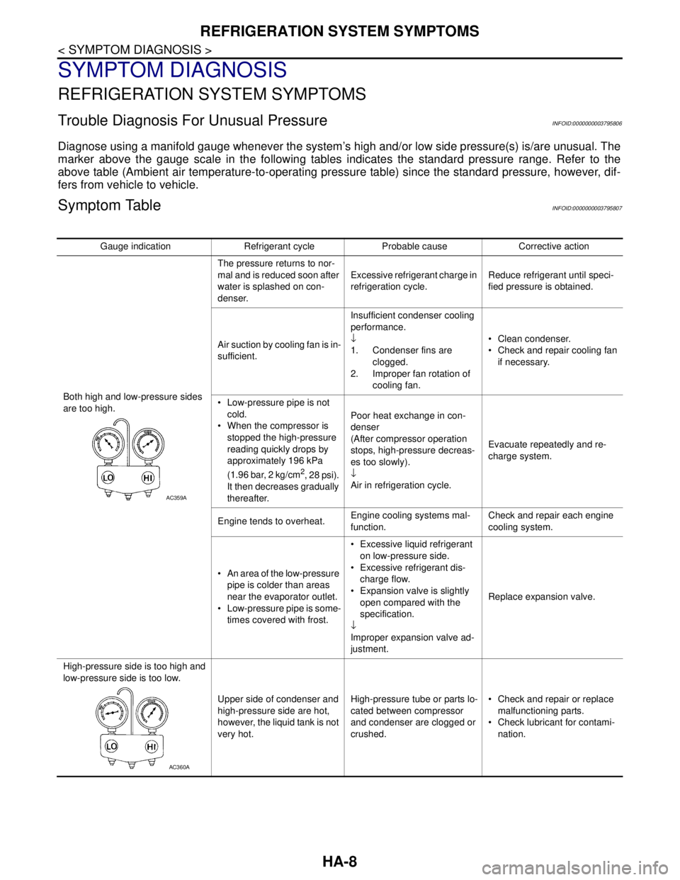
Diagnose using a manifold gauge whenever the system’s high and/or low side pressure(s) is/are unusual. The
marker above the gauge scale in the following tables indicates the standard pressure range. Refer to the
above table (Ambient air temperature-to-operating pressure table) since the standard pressure, however, dif-
fers from vehicle to vehicle.
Symptom TableINFOID:0000000003795807
Gauge indication Refrigerant cycle Probable cause Corrective action
Both high and low-pressure sides
are too high.The pressure returns to nor-
mal and is reduced soon after
water is splashed on con-
denser.Excessive refrigerant charge in
refrigeration cycle.Reduce refrigerant until speci-
fied pressure is obtained.
Air suction by cooling fan is in-
sufficient.Insufficient condenser cooling
performance.
↓
1. Condenser fins are
clogged.
2. Improper fan rotation of
cooling fan. Clean condenser.
Check and repair cooling fan
if necessary.
Low-pressure pipe is not
cold.
When the compressor is
stopped the high-pressure
reading quickly drops by
approximately 196 kPa
(1.96 bar, 2 kg/cm
2, 28 psi).
It then decreases gradually
thereafter.Poor heat exchange in con-
denser
(After compressor operation
stops, high-pressure decreas-
es too slowly).
↓
Air in refrigeration cycle.Evacuate repeatedly and re-
charge system.
Engine tends to overheat.Engine cooling systems mal-
function.Check and repair each engine
cooling system.
An area of the low-pressure
pipe is colder than areas
near the evaporator outlet.
Low-pressure pipe is some-
times covered with frost. Excessive liquid refrigerant
on low-pressure side.
Excessive refrigerant dis-
charge flow.
Expansion valve is slightly
open compared with the
specification.
↓
Improper expansion valve ad-
justment.Replace expansion valve.
High-pressure side is too high and
low-pressure side is too low.
Upper side of condenser and
high-pressure side are hot,
however, the liquid tank is not
very hot.High-pressure tube or parts lo-
cated between compressor
and condenser are clogged or
crushed. Check and repair or replace
malfunctioning parts.
Check lubricant for contami-
nation.
AC359A
AC360A
Page 3204 of 5121
MA-16
< ON-VEHICLE MAINTENANCE >
ENGINE MAINTENANCE
Watch water temperature gauge so as not to overheat engine.
9. Stop the engine and cool down to less than approximately 50°C (122°F).
Cool down using fan to reduce the time.
If necessary, refill radiator up to filler neck with engine coolant.
CAUTION:
Never adhere the engine coolant to electronic equipments. (alternator etc.)
10. Refill reservoir tank to “MAX” level line with engine coolant.
11. Repeat steps 7 through 10 two or more times with radiator cap installed until engine coolant level no
longer drops.
12. Check cooling system for leakage with engine running.
13. Warm up the engine, and check for sound of engine coolant flow while running engine from idle up to
3,000 rpm with heater temperature controller set at several position between “COOL” and “WARM”.
Sound may be noticeable at heater unit.
14. Repeat step 13 three times.
15. If sound is heard, bleed air from cooling system by repeating step 5, and steps from 7 to 14 until engine
coolant level no longer drops.
ENGINE COOLANT : FlushingINFOID:0000000003862452
1. Install reservoir tank if removed, and radiator drain plug.
CAUTION:
Be sure to clean drain plug and install with new O-ring.
If water drain plugs on cylinder block are removed, close and tighten them. Refer to EM-110, "
Dis-
assembly and Assembly".
2. Remove air duct assembly and air cleaner cases (upper and lower) assembly. Refer to EM-26, "
Exploded
View".
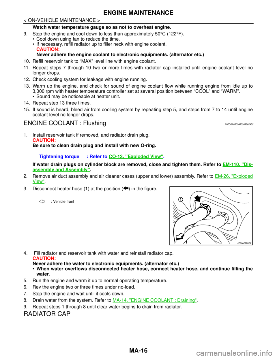
3. Disconnect heater hose (1) at the position ( ) in the figure.
4. Fill radiator and reservoir tank with water and reinstall radiator cap.
CAUTION:
Never adhere the water to electronic equipments. (alternator etc.)
When water overflows disconnected heater hose, connect heater hose, and continue filling the
water.
5. Run the engine and warm it up to normal operating temperature.
6. Rev the engine two or three times under no-load.
7. Stop the engine and wait until it cools down.
8. Drain water from the system. Refer to MA-14, "
ENGINE COOLANT : Draining".
9. Repeat steps 1 through 8 until clear water begins to drain from radiator.
RADIATOR CAP
Tightening torque : Refer to CO-13, "Exploded View".
: Vehicle front
JPBIA2226ZZ