2008 NISSAN TEANA checking oil
[x] Cancel search: checking oilPage 1672 of 5121
![NISSAN TEANA 2008 Service Manual P0300, P0301, P0302, P0303, P0304, P0305, P0306 MISFIRE
EC-211
< COMPONENT DIAGNOSIS >[VQ25DE, VQ35DE]
C
D
E
F
G
H
I
J
K
L
MA
EC
N
P O
2. Listen to each fuel injector operation.
Is the inspection resu NISSAN TEANA 2008 Service Manual P0300, P0301, P0302, P0303, P0304, P0305, P0306 MISFIRE
EC-211
< COMPONENT DIAGNOSIS >[VQ25DE, VQ35DE]
C
D
E
F
G
H
I
J
K
L
MA
EC
N
P O
2. Listen to each fuel injector operation.
Is the inspection resu](/manual-img/5/57391/w960_57391-1671.png)
P0300, P0301, P0302, P0303, P0304, P0305, P0306 MISFIRE
EC-211
< COMPONENT DIAGNOSIS >[VQ25DE, VQ35DE]
C
D
E
F
G
H
I
J
K
L
MA
EC
N
P O
2. Listen to each fuel injector operation.
Is the inspection result normal?
YES >> GO TO 5.
NO >> Perform trouble diagnosis for FUEL INJECTOR, refer to
EC-334, "
Diagnosis Procedure".
5.CHECK FUNCTION OF IGNITION COIL-I
CAUTION:
Perform the following procedure in a place with no combustible objects and good ventilation.
1. Turn ignition switch OFF.
2. Remove fuel pump fuse in IPDM E/R to release fuel pressure.
NOTE:
Do not use CONSULT-III to release fuel pressure, or fuel pressure applies again during the following pro-
cedure.
3. Start engine.
4. After engine stalls, crank it 2 or 3 times to release all fuel pressure.
5. Turn ignition switch OFF.
6. Remove all ignition coil harness connectors to avoid the electrical discharge from the ignition coils.
7. Remove ignition coil and spark plug of the cylinder to be checked.
8. Crank engine for 5 seconds or more to remove combustion gas in the cylinder.
9. Connect spark plug and harness connector to ignition coil.
10. Fix ignition coil using a rope etc. with gap of 13 - 17 mm (0.52 -
0.66 in) between the edge of the spark plug and grounded metal
portion as shown in the figure.
11. Crank engine for about 3 seconds, and check whether spark is
generated between the spark plug and the grounded metal por-
tion.
CAUTION:
Never place to the spark plug and the ignition coil within
50 cm (19.7 in) each other. Be careful not to get an electri-
cal shock while checking, because the electrical dis-
charge voltage becomes 20 kV or more.
It might damage the ignition coil if the gap of more than 17 mm (0.66 in) is made.
NOTE:
When the gap is less than 13 mm (0.52 in), a spark might be generated even if the coil is a malfunc-
tioning.
Is the inspection result normal?
YES >> GO TO 9.
NO >> GO TO 6.
6.CHECK FUNCTION OF IGNITION COIL-II
1. Turn ignition switch OFF.
2. Disconnect spark plug and connect a non-malfunctioning spark plug.
3. Crank engine for about 3 seconds, and recheck whether spark is generated between the spark plug and
the grounded metal portion.
Is the inspection result normal?
YES >> GO TO 7.
NO >> Check ignition coil, power transistor and their circuits. Refer to EC-341, "
Diagnosis Procedure". Clicking sound should be heard.
PBIB3332E
Spark should be generated.
JMBIA0066GB
Spark should be generated.
Page 1690 of 5121
![NISSAN TEANA 2008 Service Manual P0420, P0430 THREE WAY CATALYST FUNCTION
EC-229
< COMPONENT DIAGNOSIS >[VQ25DE, VQ35DE]
C
D
E
F
G
H
I
J
K
L
MA
EC
N
P O
6.CHECK FUNCTION OF IGNITION COIL-I
CAUTION:
Perform the following procedure in NISSAN TEANA 2008 Service Manual P0420, P0430 THREE WAY CATALYST FUNCTION
EC-229
< COMPONENT DIAGNOSIS >[VQ25DE, VQ35DE]
C
D
E
F
G
H
I
J
K
L
MA
EC
N
P O
6.CHECK FUNCTION OF IGNITION COIL-I
CAUTION:
Perform the following procedure in](/manual-img/5/57391/w960_57391-1689.png)
P0420, P0430 THREE WAY CATALYST FUNCTION
EC-229
< COMPONENT DIAGNOSIS >[VQ25DE, VQ35DE]
C
D
E
F
G
H
I
J
K
L
MA
EC
N
P O
6.CHECK FUNCTION OF IGNITION COIL-I
CAUTION:
Perform the following procedure in a place with no combustible objects and good ventilation.
1. Turn ignition switch OFF.
2. Remove fuel pump fuse in IPDM E/R to release fuel pressure.
NOTE:
Do not use CONSULT-III to release fuel pressure, or fuel pressure applies again during the following pro-
cedure.
3. Start engine.
4. After engine stalls, crank it 2 or 3 times to release all fuel pressure.
5. Turn ignition switch OFF.
6. Remove all ignition coil harness connectors to avoid the electrical discharge from the ignition coils.
7. Remove ignition coil and spark plug of the cylinder to be checked.
8. Crank engine for 5 seconds or more to remove combustion gas in the cylinder.
9. Connect spark plug and harness connector to ignition coil.
10. Fix ignition coil using a rope etc. with gap of 13 - 17 mm (0.52 -
0.66 in) between the edge of the spark plug and grounded metal
portion as shown in the figure.
11. Crank engine for about 3 seconds, and check whether spark is
generated between the spark plug and the grounded metal por-
tion.
CAUTION:
Never place to the spark plug and the ignition coil within
50 cm (19.7 in) each other. Be careful not to get an electri-
cal shock while checking, because the electrical dis-
charge voltage becomes 20 kV or more.
It might damage the ignition coil if the gap of more than 17 mm (0.66 in) is made.
NOTE:
When the gap is less than 13 mm (0.52 in), a spark might be generated even if the coil is a malfunc-
tioning.
Is the inspection result normal?
YES >> GO TO 10.
NO >> GO TO 7.
7.CHECK FUNCTION OF IGNITION COIL-II
1. Turn ignition switch OFF.
2. Disconnect spark plug and connect a non-malfunctioning spark plug.
3. Crank engine for about 3 seconds, and recheck whether spark is generated between the spark plug and
the grounded metal portion.
Is the inspection result normal?
YES >> GO TO 8.
NO >> Check ignition coil, power transistor and their circuit. Refer to EC-341, "
Diagnosis Procedure".
8.CHECK SPARK PLUGSpark should be generated.
JMBIA0066GB
Spark should be generated.
Page 1805 of 5121
![NISSAN TEANA 2008 Service Manual EC-344
< COMPONENT DIAGNOSIS >[VQ25DE, VQ35DE]
IGNITION SIGNAL
YES >> GO TO 10.
NO >> Replace malfunctioning ignition coil with power transistor.
10.CHECK INTERMITTENT INCIDENT
Refer to GI-35, "
Inter NISSAN TEANA 2008 Service Manual EC-344
< COMPONENT DIAGNOSIS >[VQ25DE, VQ35DE]
IGNITION SIGNAL
YES >> GO TO 10.
NO >> Replace malfunctioning ignition coil with power transistor.
10.CHECK INTERMITTENT INCIDENT
Refer to GI-35, "
Inter](/manual-img/5/57391/w960_57391-1804.png)
EC-344
< COMPONENT DIAGNOSIS >[VQ25DE, VQ35DE]
IGNITION SIGNAL
YES >> GO TO 10.
NO >> Replace malfunctioning ignition coil with power transistor.
10.CHECK INTERMITTENT INCIDENT
Refer to GI-35, "
Intermittent Incident".
>> INSPECTION END
Component Inspection (Ignition Coil with Power Transistor)INFOID:0000000003856851
1.CHECK IGNITION COIL WITH POWER TRANSISTOR-I
1. Turn ignition switch OFF.
2. Disconnect ignition coil harness connector.
3. Check resistance between ignition coil terminals as per the following.
Is the inspection result normal?
YES >> GO TO 2.
NO >> Replace malfunctioning ignition coil with power transistor.
2.CHECK IGNITION COIL WITH POWER TRANSISTOR-II
CAUTION:
Perform the following procedure in a place with no combustible objects and good ventilation.
1. Turn ignition switch OFF.
2. Reconnect all harness connectors disconnected.
3. Remove fuel pump fuse in IPDM E/R to release fuel pressure.
NOTE:
Do not use CONSULT-III to release fuel pressure, or fuel pressure applies again during the following pro-
cedure.
4. Start engine.
5. After engine stalls, crank it 2 or 3 times to release all fuel pressure.
6. Turn ignition switch OFF.
7. Remove all ignition coil harness connectors to avoid the electrical discharge from the ignition coils.
8. Remove ignition coil and spark plug of the cylinder to be checked.
9. Crank engine for 5 seconds or more to remove combustion gas in the cylinder.
10. Connect spark plug and harness connector to ignition coil.
11. Fix ignition coil using a rope etc. with gap of 13 - 17 mm (0.52 -
0.66 in) between the edge of the spark plug and grounded metal
portion as shown in the figure.
12. Crank engine for about 3 seconds, and check whether spark is
generated between the spark plug and the grounded metal por-
tion.
CAUTION:
Never place to the spark plug and the ignition coil within
50 cm (19.7 in) each other. Be careful not to get an electri-
cal shock while checking, because the electrical dis-
charge voltage becomes 20 kV or more.
It might damage the ignition coil if the gap of more than 17 mm (0.66 in) is made.
NOTE:
When the gap is less than 13 mm (0.52 in), a spark might be generated even if the coil is a malfunc-
tioning.
Is the inspection result normal?
Terminal No. (Polarity) Resistance Ω [at 25°C (77°F)]
1 and 2 Except 0 or ∞
1 and 3
Except 0
2 and 3
Spark should be generated.
JMBIA0066GB
Page 1876 of 5121

EM-1
ENGINE
C
D
E
F
G
H
I
J
K
L
M
SECTION EM
A
EM
N
O
P
CONTENTS
ENGINE MECHANICAL
SYMPTOM DIAGNOSIS ...............................3
NOISE, VIBRATION AND HARSHNESS
(NVH) TROUBLESHOOTING .............................
3
NVH Troubleshooting - Engine Noise .......................3
Use the Chart Below to Help You Find the Cause
of the Symptom .........................................................
4
PRECAUTION ...............................................5
PRECAUTIONS ...................................................5
Precaution for Procedure without Cowl Top Cover ......5
Precaution for Supplemental Restraint System
(SRS) "AIR BAG" and "SEAT BELT PRE-TEN-
SIONER" ...................................................................
5
Precaution Necessary for Steering Wheel Rota-
tion after Battery Disconnect .....................................
5
Precaution for Drain Engine Coolant and Engine
Oil ..............................................................................
6
Precaution for Disconnecting Fuel Piping .................6
Precaution for Removal and Disassembly ................6
Precaution for Inspection, Repair and Replace-
ment ..........................................................................
6
Precaution for Assembly and Installation ..................6
Precaution for Angle Tightening ................................6
Precaution for Liquid Gasket .....................................7
PREPARATION ............................................8
PREPARATION ...................................................8
Special Service Tool .................................................8
Commercial Service Tool ..........................................9
ON-VEHICLE MAINTENANCE ....................12
DRIVE BELT .......................................................12
Exploded View ........................................................12
Checking .................................................................12
Tension Adjustment ................................................12
Removal and Installation .........................................12
AIR CLEANER FILTER ......................................14
Removal and Installation .........................................14
SPARK PLUG ...................................................15
Exploded View .........................................................15
Removal and Installation .........................................15
Inspection ................................................................16
CAMSHAFT VALVE CLEARANCE ..................17
Inspection and Adjustment ......................................17
COMPRESSION PRESSURE ...........................22
Inspection ................................................................22
ON-VEHICLE REPAIR .................................24
ENGINE COVER ...............................................24
Exploded View .........................................................24
Removal and Installation .........................................24
DRIVE BELT AUTO TENSIONER AND IDLER
PULLEY .............................................................
25
Exploded View .........................................................25
Removal and Installation .........................................25
AIR CLEANER AND AIR DUCT .......................26
Exploded View .........................................................26
Removal and Installation .........................................26
Inspection ................................................................27
INTAKE MANIFOLD COLLECTOR ..................28
Exploded View .........................................................28
Removal and Installation .........................................29
INTAKE MANIFOLD .........................................32
Exploded View .........................................................32
Removal and Installation .........................................32
Inspection ................................................................33
EXHAUST MANIFOLD AND THREE WAY
CATALYST ........................................................
34
Exploded View .........................................................34
Removal and Installation .........................................34
Inspection ................................................................37
Page 1887 of 5121

EM-12
< ON-VEHICLE MAINTENANCE >
DRIVE BELT
ON-VEHICLE MAINTENANCE
DRIVE BELT
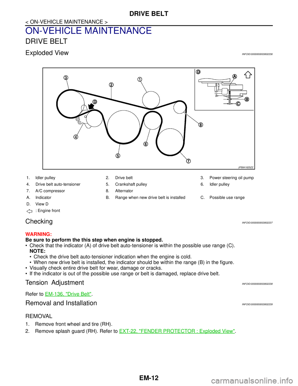
Exploded ViewINFOID:0000000003802236
CheckingINFOID:0000000003802237
WARNING:
Be sure to perform the this step when engine is stopped.
Check that the indicator (A) of drive belt auto-tensioner is within the possible use range (C).
NOTE:
Check the drive belt auto-tensioner indication when the engine is cold.
When new drive belt is installed, the indicator should be within the range (B) in the figure.
Visually check entire drive belt for wear, damage or cracks.
If the indicator is out of the possible use range or belt is damaged, replace drive belt.
Tension AdjustmentINFOID:0000000003802238
Refer to EM-136, "Drive Belt".
Removal and InstallationINFOID:0000000003802239
REMOVAL
1. Remove front wheel and tire (RH).
2. Remove splash guard (RH). Refer to EXT-22, "
FENDER PROTECTOR : Exploded View".
JPBIA1625ZZ
1. Idler pulley 2. Drive belt 3. Power steering oil pump
4. Drive belt auto-tensioner 5. Crankshaft pulley 6. Idler pulley
7. A/C compressor 8. Alternator
A. Indicator B. Range when new drive belt is installed C. Possible use range
D. View D
: Engine front
Page 1897 of 5121

EM-22
< ON-VEHICLE MAINTENANCE >
COMPRESSION PRESSURE
COMPRESSION PRESSURE
InspectionINFOID:0000000003802245
1. Warm up engine thoroughly. Then, stop it.
2. Release fuel pressure. Refer to EC-411, "
Inspection".
3. Disconnect fuel pump fuse to avoid fuel injection during measurement. Refer to EC-20,
"ComponentPartsLocation".
4. Remove engine cover. Refer to EM-24, "
Exploded View".
5. Remove ignition coil and spark plug from each cylinder. Refer to EM-49, "
Exploded View".
6. Connect engine tachometer (not required in use of CONSULT-III).
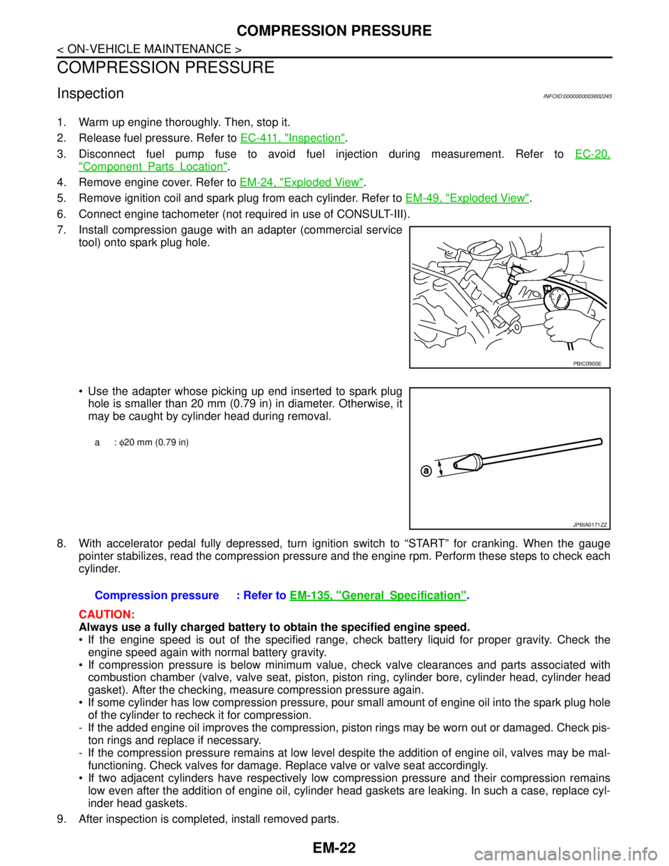
7. Install compression gauge with an adapter (commercial service
tool) onto spark plug hole.
Use the adapter whose picking up end inserted to spark plug
hole is smaller than 20 mm (0.79 in) in diameter. Otherwise, it
may be caught by cylinder head during removal.
8. With accelerator pedal fully depressed, turn ignition switch to “START” for cranking. When the gauge
pointer stabilizes, read the compression pressure and the engine rpm. Perform these steps to check each
cylinder.
CAUTION:
Always use a fully charged battery to obtain the specified engine speed.
If the engine speed is out of the specified range, check battery liquid for proper gravity. Check the
engine speed again with normal battery gravity.
If compression pressure is below minimum value, check valve clearances and parts associated with
combustion chamber (valve, valve seat, piston, piston ring, cylinder bore, cylinder head, cylinder head
gasket). After the checking, measure compression pressure again.
If some cylinder has low compression pressure, pour small amount of engine oil into the spark plug hole
of the cylinder to recheck it for compression.
- If the added engine oil improves the compression, piston rings may be worn out or damaged. Check pis-
ton rings and replace if necessary.
- If the compression pressure remains at low level despite the addition of engine oil, valves may be mal-
functioning. Check valves for damage. Replace valve or valve seat accordingly.
If two adjacent cylinders have respectively low compression pressure and their compression remains
low even after the addition of engine oil, cylinder head gaskets are leaking. In such a case, replace cyl-
inder head gaskets.
9. After inspection is completed, install removed parts.
PBIC0900E
a: φ20 mm (0.79 in)
JPBIA0171ZZ
Compression pressure : Refer to EM-135, "GeneralSpecification".
Page 1922 of 5121

FUEL INJECTOR AND FUEL TUBE
EM-47
< ON-VEHICLE REPAIR >
C
D
E
F
G
H
I
J
K
L
MA
EM
N
P O
Upper and lower O-ring are different. Be careful not to confuse them.
Handle O-ring with bare hands. Never wear gloves.
Lubricate O-ring with new engine oil.
Never clean O-ring with solvent.
Check that O-ring and its mating part are free of foreign material.
When installing O-ring, be careful not to scratch it with tool or fingernails. Also be careful not to
twist or stretch O-ring. If O-ring was stretched while it was being attached, never insert it quickly
into fuel tube.
Insert O-ring straight into fuel injector. Never decenter or twist it.
3. Install fuel injector to fuel tube as follows:
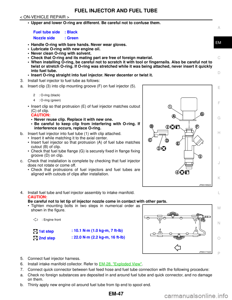
a. Insert clip (3) into clip mounting groove (F) on fuel injector (5).
Insert clip so that protrusion (E) of fuel injector matches cutout
(C) of clip.
CAUTION:
Never reuse clip. Replace it with new one.
Be careful to keep clip from interfering with O-ring. If
interference occurs, replace O-ring.
b. Insert fuel injector into fuel tube (1) with clip attached.
Insert it while matching it to the axial center.
Insert fuel injector so that protrusion (A) of fuel tube matches
cutout (B) of clip.
Check that fuel tube flange (G) is securely fixed in flange fixing
groove (D) on clip.
c. Check that installation is complete by checking that fuel injector
does not rotate or come off.
Check that protrusions of fuel injectors and fuel tubes are
aligned with cutouts of clips after installation.
4. Install fuel tube and fuel injector assembly to intake manifold.
CAUTION:
Be careful not to let tip of injector nozzle come in contact with other parts.
Tighten mounting bolts in two steps in numerical order as
shown in the figure.
5. Connect fuel injector harness.
6. Install intake manifold collector. Refer to EM-28, "
Exploded View".
7. Connect quick connector between fuel feed hose and fuel tube connection with the following procedure:
a. Check no foreign substances are deposited in and around fuel tube and quick connector, and no damage
on them.
b. Thinly apply new engine oil around fuel tube from tip end to spool end.Fuel tube side : Black
Nozzle side : Green
2 : O-ring (black)
4 : O-ring (green)
JPBIA1959ZZ
: Engine front
1st step: 10.1 N·m (1.0 kg-m, 7 ft-lb)
2nd step: 22.0 N·m (2.2 kg-m, 16 ft-lb)
JPBIA1715ZZ
Page 1940 of 5121

TIMING CHAIN
EM-65
< ON-VEHICLE REPAIR >
C
D
E
F
G
H
I
J
K
L
MA
EM
N
P O
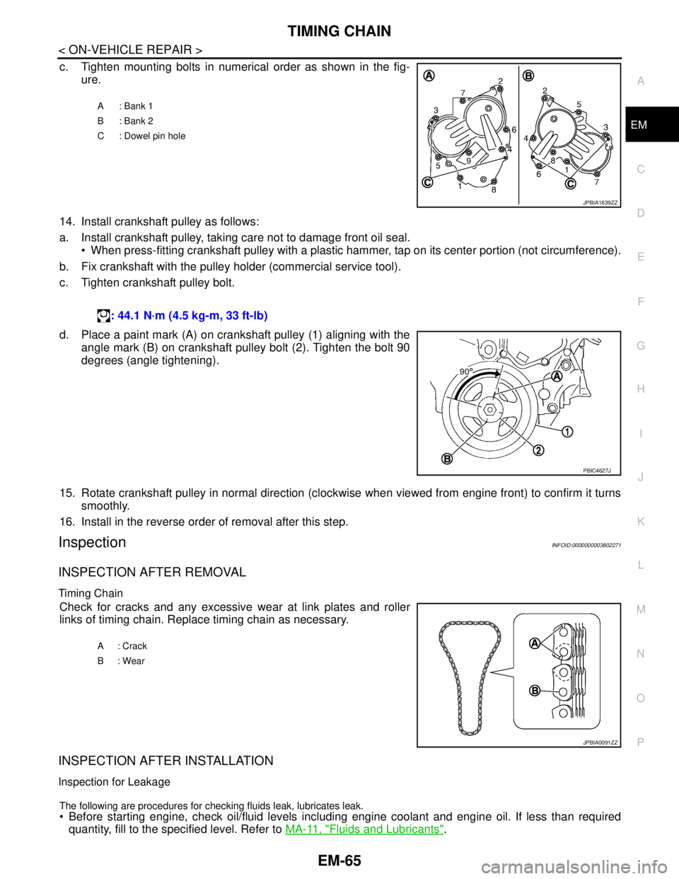
c. Tighten mounting bolts in numerical order as shown in the fig-
ure.
14. Install crankshaft pulley as follows:
a. Install crankshaft pulley, taking care not to damage front oil seal.
When press-fitting crankshaft pulley with a plastic hammer, tap on its center portion (not circumference).
b. Fix crankshaft with the pulley holder (commercial service tool).
c. Tighten crankshaft pulley bolt.
d. Place a paint mark (A) on crankshaft pulley (1) aligning with the
angle mark (B) on crankshaft pulley bolt (2). Tighten the bolt 90
degrees (angle tightening).
15. Rotate crankshaft pulley in normal direction (clockwise when viewed from engine front) to confirm it turns
smoothly.
16. Install in the reverse order of removal after this step.
InspectionINFOID:0000000003802271
INSPECTION AFTER REMOVAL
Timing Chain
Check for cracks and any excessive wear at link plates and roller
links of timing chain. Replace timing chain as necessary.
INSPECTION AFTER INSTALLATION
Inspection for Leakage
The following are procedures for checking fluids leak, lubricates leak.
Before starting engine, check oil/fluid levels including engine coolant and engine oil. If less than required
quantity, fill to the specified level. Refer to MA-11, "
Fluids and Lubricants".
A: Bank 1
B: Bank 2
C : Dowel pin hole
JPBIA1639ZZ
: 44.1 N·m (4.5 kg-m, 33 ft-lb)
PBIC4627J
A: Crack
B: Wear
JPBIA0091ZZ