2008 NISSAN TEANA checking oil
[x] Cancel search: checking oilPage 2591 of 5121
HA-22
< PREPARATION >
PREPARATION
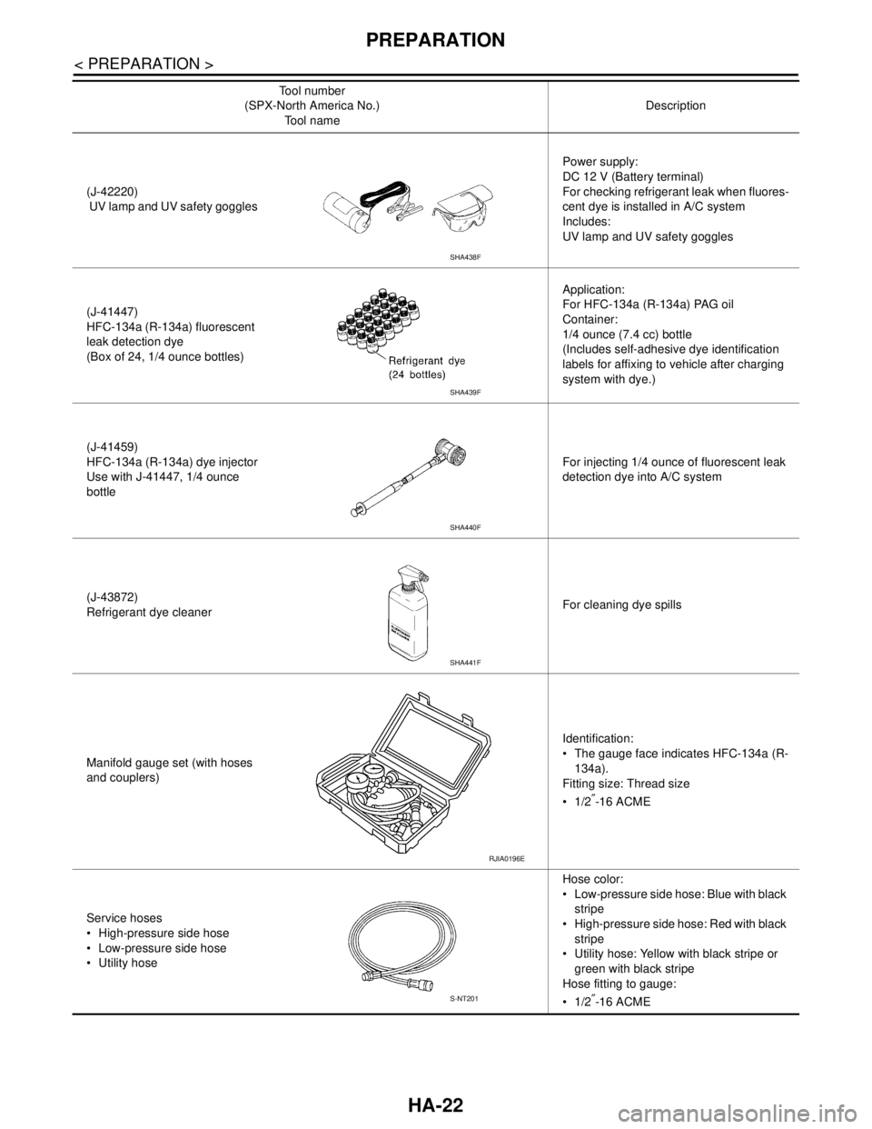
(J-42220)
UV lamp and UV safety gogglesPower supply:
DC 12 V (Battery terminal)
For checking refrigerant leak when fluores-
cent dye is installed in A/C system
Includes:
UV lamp and UV safety goggles
(J-41447)
HFC-134a (R-134a) fluorescent
leak detection dye
(Box of 24, 1/4 ounce bottles)Application:
For HFC-134a (R-134a) PAG oil
Container:
1/4 ounce (7.4 cc) bottle
(Includes self-adhesive dye identification
labels for affixing to vehicle after charging
system with dye.)
(J-41459)
HFC-134a (R-134a) dye injector
Use with J-41447, 1/4 ounce
bottleFor injecting 1/4 ounce of fluorescent leak
detection dye into A/C system
(J-43872)
Refrigerant dye cleanerFor cleaning dye spills
Manifold gauge set (with hoses
and couplers)Identification:
The gauge face indicates HFC-134a (R-
134a).
Fitting size: Thread size
1/2
″-16 ACME
Service hoses
High-pressure side hose
Low-pressure side hose
Utility hoseHose color:
Low-pressure side hose: Blue with black
stripe
High-pressure side hose: Red with black
stripe
Utility hose: Yellow with black stripe or
green with black stripe
Hose fitting to gauge:
1/2
″-16 ACME Tool number
(SPX-North America No.)
Tool nameDescription
SHA438F
SHA439F
SHA440F
SHA441F
RJIA0196E
S-NT201
Page 2601 of 5121
HA-32
< ON-VEHICLE MAINTENANCE >
FLUORESCENT LEAK DETECTOR
FLUORESCENT LEAK DETECTOR
InspectionINFOID:0000000003795981
CHECKING SYSTEM FOR LEAKAGES USING THE FLUORESCENT LEAK DETECTOR
1. Check A/C system for leakages using the UV lamp and safety goggles (SST: J-42220) in a low sunlight
area (area without windows preferable). Illuminate all components, fittings and lines. The dye appears as
a bright green/yellow area at the point of leakage. Fluorescent dye observed at the evaporator drain open-
ing indicates an evaporator core assembly (tubes, core or expansion valve) leakage.
2. Use an adjustable mirror or wipe the area with a clean shop rag or cloth, with the UV lamp for dye residue
if the suspected area is difficult to see.
3. Remove any residual dye using dye cleaner (SST: J-43872) to prevent future misdiagnosis after the leak-
age is repaired.
4. Perform a system performance check and verify the leakage repair with an approved electrical leak detec-
tor.
NOTE:
Other gases in the work area or substances on the A/C components, for example, anti-freeze, windshield
washer fluid, solvents and lubricants, may falsely trigger the leak detector. Make sure the surfaces to be
checked are clean.
Clean with a dry cloth or blow off with shop air.
Do not allow the sensor tip of the detector to contact with any substance. This may also cause false readings
and may damage the detector.
DYE INJECTION
(This procedure is only necessary when recharging the system or when the compressor has seized and was
replaced.)
1. Check A/C system static (at rest) pressure. Pressure must be at least 345 kPa (3.45 bar, 3.52 kg/cm
2, 50
psi).
2. Pour one bottle (1/4 ounce / 7.4 cc) of the A/C refrigerant dye into the injector tool (SST: J-41459).
3. Connect the injector tool to the A/C low-pressure side service valve.
4. Start the engine. Then switch A/C ON.
5. Inject one bottle (1/4 ounce / 7.4 cc) of fluorescent dye through the low-pressure service valve using dye
injector tool (SST: J-41459) (refer to the manufacture’s operating instructions) when the A/C operating
(compressor running).
6. Disconnect the injector tool from the service valve with the engine still running.
CAUTION:
Be careful when replacing the A/C system or a component, pour the dye directly into the open sys-
tem connection and proceed with the service procedures.
7. Operate the A/C system for a minimum of 20 minutes to mix the dye with the system oil. Depending on the
leakage size, operating conditions and location of the leakage, it may take from minutes to days for the
dye to penetrate a leakage and become visible.
8. Attach a blue label if necessary.
Page 2606 of 5121
COMPRESSOR
HA-37
< ON-VEHICLE REPAIR >
C
D
E
F
G
H
J
K
L
MA
B
HA
N
O
P
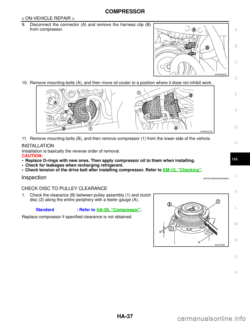
9. Disconnect the connector (A) and remove the harness clip (B)
from compressor.
10. Remove mounting bolts (A), and then move oil cooler to a position where it dose not inhibit work.
11. Remove mounting bolts (B), and then remove compressor (1) from the lower side of the vehicle.
INSTALLATION
Installation is basically the reverse order of removal.
CAUTION:
Replace O-rings with new ones. Then apply compressor oil to them when installing.
Check for leakages when recharging refrigerant.
Check tension of the drive belt after installing compressor. Refer to EM-12, "
Checking".
InspectionINFOID:0000000003839904
CHECK DISC TO PULLEY CLEARANCE
1. Check the clearance (B) between pulley assembly (1) and clutch
disc (2) along the entire periphery with a feeler gauge (A).
Replace compressor if specified clearance is not obtained.
JPIIA0530ZZ
JPIIA0531ZZ
Standard : Refer to HA-59, "Compressor".
SJIA1918ESJIA1918E
Page 3179 of 5121
ENGINE OIL
LU-7
< ON-VEHICLE MAINTENANCE >
C
D
E
F
G
H
I
J
K
L
MA
LU
N
P O
ON-VEHICLE MAINTENANCE
ENGINE OIL
InspectionINFOID:0000000003793121
ENGINE OIL LEVEL
NOTE:
Before starting engine, put vehicle horizontally and check the engine oil level. If engine is already started, stop
it and allow 10 minutes before checking.
1. Pull out oil level gauge and wipe it clean.
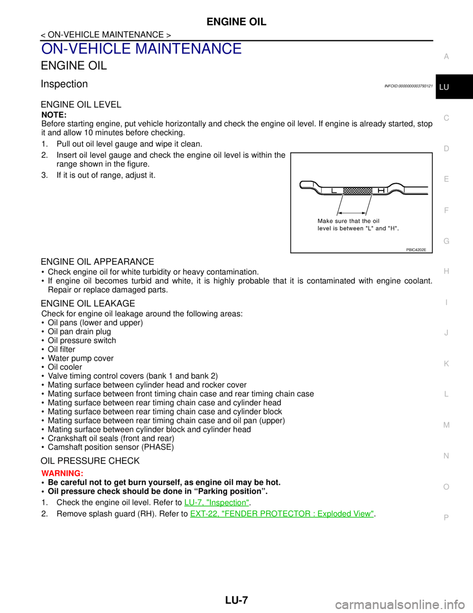
2. Insert oil level gauge and check the engine oil level is within the
range shown in the figure.
3. If it is out of range, adjust it.
ENGINE OIL APPEARANCE
Check engine oil for white turbidity or heavy contamination.
If engine oil becomes turbid and white, it is highly probable that it is contaminated with engine coolant.
Repair or replace damaged parts.
ENGINE OIL LEAKAGE
Check for engine oil leakage around the following areas:
Oil pans (lower and upper)
Oil pan drain plug
Oil pressure switch
Oil filter
Water pump cover
Oil cooler
Valve timing control covers (bank 1 and bank 2)
Mating surface between cylinder head and rocker cover
Mating surface between front timing chain case and rear timing chain case
Mating surface between rear timing chain case and cylinder head
Mating surface between rear timing chain case and cylinder block
Mating surface between rear timing chain case and oil pan (upper)
Mating surface between cylinder block and cylinder head
Crankshaft oil seals (front and rear)
Camshaft position sensor (PHASE)
OIL PRESSURE CHECK
WARNING:
• Be careful not to get burn yourself, as engine oil may be hot.
Oil pressure check should be done in “Parking position”.
1. Check the engine oil level. Refer to LU-7, "
Inspection".
2. Remove splash guard (RH). Refer to EXT-22, "
FENDER PROTECTOR : Exploded View".
PBIC4202E
Page 3189 of 5121
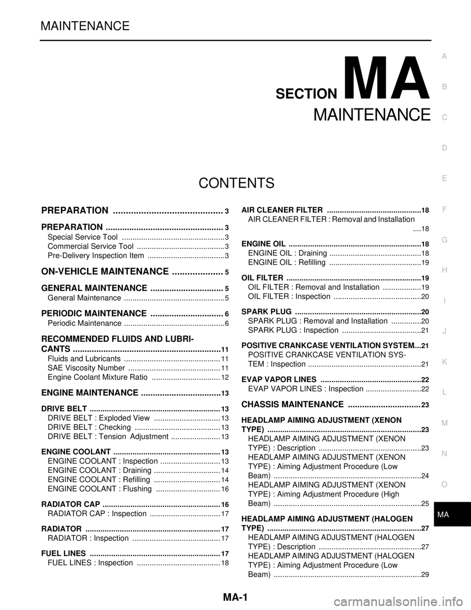
MA-1
MAINTENANCE
C
DE
F
G H
I
J
K L
M B
MA
SECTION MA
N
O A
CONTENTS
MAINTENANCE
PREPARATION .............
...............................3
PREPARATION .............................................. .....3
Special Service Tool ........................................... ......3
Commercial Service Tool ..........................................3
Pre-Delivery Inspection Item .....................................3
ON-VEHICLE MAINTENANCE .....................5
GENERAL MAINTENANCE ........................... .....5
General Maintenance .......................................... ......5
PERIODIC MAINTENANCE ................................6
Periodic Maintenance .......................................... ......6
RECOMMENDED FLUIDS AND LUBRI-
CANTS ................................................................
11
Fluids and Lubricants .......................................... ....11
SAE Viscosity Number ............................................11
Engine Coolant Mixture Ratio .................................12
ENGINE MAINTENANCE ...................................13
DRIVE BELT .......................................................... ....13
DRIVE BELT : Exploded View ................................13
DRIVE BELT : Checking .........................................13
DRIVE BELT : Tension Adjustment ........................13
ENGINE COOLANT ............................................... ....13
ENGINE COOLANT : Inspection .............................13
ENGINE COOLANT : Draining ................................14
ENGINE COOLANT : Refilling ................................14
ENGINE COOLANT : Flushing ...............................16
RADIATOR CAP .................................................... ....16
RADIATOR CAP : Inspection ..................................17
RADIATOR ............................................................ ....17
RADIATOR : Inspection ..........................................17
FUEL LINES .......................................................... ....17
FUEL LINES : Inspection ........................................18
AIR CLEANER FILTER ......................................... ....18
AIR CLEANER FILTER : Removal and Installation
....
18
ENGINE OIL ........................................................... ....18
ENGINE OIL : Draining ............................................18
ENGINE OIL : Refilling ............................................19
OIL FILTER ............................................................ ....19
OIL FILTER : Removal and Installation ...................19
OIL FILTER : Inspection ..........................................20
SPARK PLUG ........................................................ ....20
SPARK PLUG : Removal and Installation ...............20
SPARK PLUG : Inspection ......................................21
POSITIVE CRANKCASE VENTILATION SYSTEM ....21
POSITIVE CRANKCASE VENTILATION SYS-
TEM : Inspection ......................................................
21
EVAP VAPOR LINES ............................................ ....22
EVAP VAPOR LINES : Inspection ...........................22
CHASSIS MAINTENANCE ...............................23
HEADLAMP AIMING ADJUSTMENT (XENON
TYPE) .......... ................................. ..............................
23
HEADLAMP AIMING ADJUSTMENT (XENON
TYPE) : Description ............................................. ....
23
HEADLAMP AIMING ADJUSTMENT (XENON
TYPE) : Aiming Adjustment Procedure (Low
Beam) ......................................................................
24
HEADLAMP AIMING ADJUSTMENT (XENON
TYPE) : Aiming Adjustment Procedure (High
Beam) ......................................................................
25
HEADLAMP AIMING ADJUSTMENT (HALOGEN
TYPE) ........................................... ..............................
27
HEADLAMP AIMING ADJUSTMENT (HALOGEN
TYPE) : Description ............................................. ....
27
HEADLAMP AIMING ADJUSTMENT (HALOGEN
TYPE) : Aiming Adjustment Procedure (Low
Beam) ......................................................................
29
Page 3190 of 5121

MA-2
HEADLAMP AIMING ADJUSTMENT (HALOGEN
TYPE) : Aiming Adjustment Procedure (High
Beam) .....................................................................
30
EXHAUST SYSTEM ..................................................31
EXHAUST SYSTEM : Inspection ...........................32
CVT FLUID: RE0F10A ..............................................32
CVT FLUID: RE0F10A : Inspection ........................32
CVT FLUID: RE0F10A : Changing .........................33
CVT FLUID: RE0F09B ..............................................34
CVT FLUID: RE0F09B : Inspection ........................34
CVT FLUID: RE0F09B : Changing .........................35
WHEELS (BONDING WEIGHT TYPE) .....................35
WHEELS (BONDING WEIGHT TYPE) : Adjust-
ment ........................................................................
35
BRAKE FLUID LEVEL AND LEAKS ........................37
BRAKE FLUID LEVEL AND LEAKS : Inspection ...37
BRAKE LINES AND CABLES ..................................37
BRAKE LINES AND CABLES : Inspection .............38
BRAKE FLUID ..........................................................38
BRAKE FLUID : Changing ......................................38
DISC BRAKE ............................................................38
DISC BRAKE : Inspection ......................................38
DISC BRAKE : Front Disc Brake ............................39
DISC BRAKE : Rear Disc Brake .............................39
STEERING GEAR AND LINKAGE ...........................39
STEERING GEAR AND LINKAGE : Inspection ......39
POWER STEERING FLUID AND LINES ..................39
POWER STEERING FLUID AND LINES : Inspec-
tion ..........................................................................
40
AXLE AND SUSPENSION PARTS ...........................40
AXLE AND SUSPENSION PARTS : Inspection .....40
DRIVE SHAFT ...........................................................40
DRIVE SHAFT : Inspection .....................................41
BODY MAINTENANCE .....................................42
LOCKS, HINGES AND HOOD LATCH .....................42
LOCKS, HINGES AND HOOD LATCH : Lubricat-
ing ...........................................................................
42
SEAT BELT, BUCKLES, RETRACTORS, AN-
CHORS AND ADJUSTERS ......................................
42
SEAT BELT, BUCKLES, RETRACTORS, AN-
CHORS AND ADJUSTERS : Inspection .................
42
BODY CORROSION .................................................42
BODY CORROSION : Checking Body Corrosion ...42
SERVICE DATA AND SPECIFICATIONS
(SDS) ..........................................................
44
SERVICE DATA AND SPECIFICATIONS
(SDS) .................................................................
44
DRIVE BELTS ...........................................................44
DRIVE BELTS : Drive Belt ......................................44
ENGINE COOLANT ..................................................44
ENGINE COOLANT : Periodical Maintenance
Specification ............................................................
44
ENGINE OIL ..............................................................44
ENGINE OIL :
Periodical Maintenance Specification ....................
44
SPARK PLUG ...........................................................44
SPARK PLUG : Spark Plug ....................................44
ROAD WHEEL ..........................................................44
ROAD WHEEL : Road Wheel .................................44
Page 3191 of 5121
PREPARATION
MA-3
< PREPARATION >
C
D
E
F
G
H
I
J
K
L
MB
MAN
OA
PREPARATION
PREPARATION
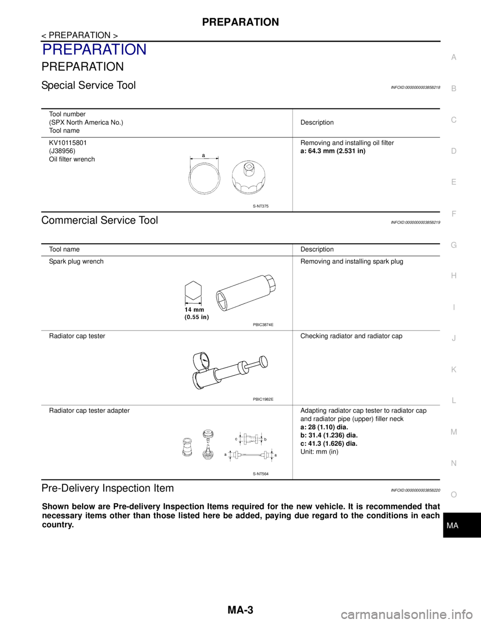
Special Service ToolINFOID:0000000003858218
Commercial Service ToolINFOID:0000000003858219
Pre-Delivery Inspection ItemINFOID:0000000003858220
Shown below are Pre-delivery Inspection Items required for the new vehicle. It is recommended that
necessary items other than those listed here be added, paying due regard to the conditions in each
country.
Tool number
(SPX North America No.)
Tool nameDescription
KV10115801
(J38956)
Oil filter wrenchRemoving and installing oil filter
a: 64.3 mm (2.531 in)
S-NT375
Tool nameDescription
Spark plug wrench Removing and installing spark plug
Radiator cap tester Checking radiator and radiator cap
Radiator cap tester adapter Adapting radiator cap tester to radiator cap
and radiator pipe (upper) filler neck
a: 28 (1.10) dia.
b: 31.4 (1.236) dia.
c: 41.3 (1.626) dia.
Unit: mm (in)
PBIC3874E
PBIC1982E
S-NT564
Page 3194 of 5121
MA-6
< ON-VEHICLE MAINTENANCE >
PERIODIC MAINTENANCE
PERIODIC MAINTENANCE
Periodic MaintenanceINFOID:0000000003858222
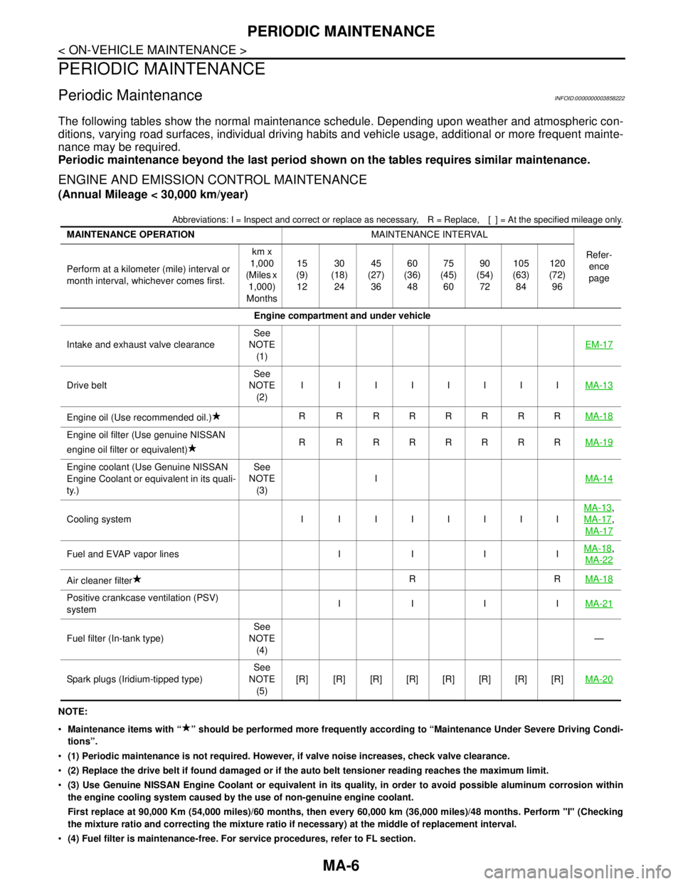
The following tables show the normal maintenance schedule. Depending upon weather and atmospheric con-
ditions, varying road surfaces, individual driving habits and vehicle usage, additional or more frequent mainte-
nance may be required.
Periodic maintenance beyond the last period shown on the tables requires similar maintenance.
ENGINE AND EMISSION CONTROL MAINTENANCE
(Annual Mileage < 30,000 km/year)
Abbreviations: I = Inspect and correct or replace as necessary, R = Replace,[ ] = At the specified mileage only.
NOTE:
Maintenance items with “ ” should be performed more frequently according to “Maintenance Under Severe Driving Condi-
tions”.
(1) Periodic maintenance is not required. However, if valve noise increases, check valve clearance.
(2) Replace the drive belt if found damaged or if the auto belt tensioner reading reaches the maximum limit.
(3) Use Genuine NISSAN Engine Coolant or equivalent in its quality, in order to avoid possible aluminum corrosion within
the engine cooling system caused by the use of non-genuine engine coolant.
First replace at 90,000 Km (54,000 miles)/60 months, then every 60,000 km (36,000 miles)/48 months. Perform "I" (Checking
the mixture ratio and correcting the mixture ratio if necessary) at the middle of replacement interval.
(4) Fuel filter is maintenance-free. For service procedures, refer to FL section. MAINTENANCE OPERATIONMAINTENANCE INTERVAL
Refer-
ence
page Perform at a kilometer (mile) interval or
month interval, whichever comes first.km x
1,000
(Miles x
1,000)
Months15
(9)
1230
(18)
2445
(27)
3660
(36)
4875
(45)
6090
(54)
72105
(63)
84120
(72)
96
Engine compartment and under vehicle
Intake and exhaust valve clearanceSee
NOTE
(1)EM-17
Drive beltSee
NOTE
(2)I I IIIIIIMA-13
Engine oil (Use recommended oil.)R R RRRRRRMA-18
Engine oil filter (Use genuine NISSAN
engine oil filter or equivalent)R R RRRRRRMA-19
Engine coolant (Use Genuine NISSAN
Engine Coolant or equivalent in its quali-
ty.)See
NOTE
(3)IMA-14
Cooling system I I IIIIIIMA-13
,
MA-17
,
MA-17
Fuel and EVAP vapor lines I I I IMA-18,
MA-22
Air cleaner filterRRMA-18
Positive crankcase ventilation (PSV)
systemIIIIMA-21
Fuel filter (In-tank type)See
NOTE
(4)—
Spark plugs (Iridium-tipped type)See
NOTE
(5)[R] [R] [R] [R] [R] [R] [R] [R]MA-20