2008 NISSAN LATIO ECU
[x] Cancel search: ECUPage 748 of 2771
BRAKE MASTER CYLINDER
BR-17
< SERVICE INFORMATION >
C
D
E
G
H
I
J
K
L
MA
B
BR
N
O
P
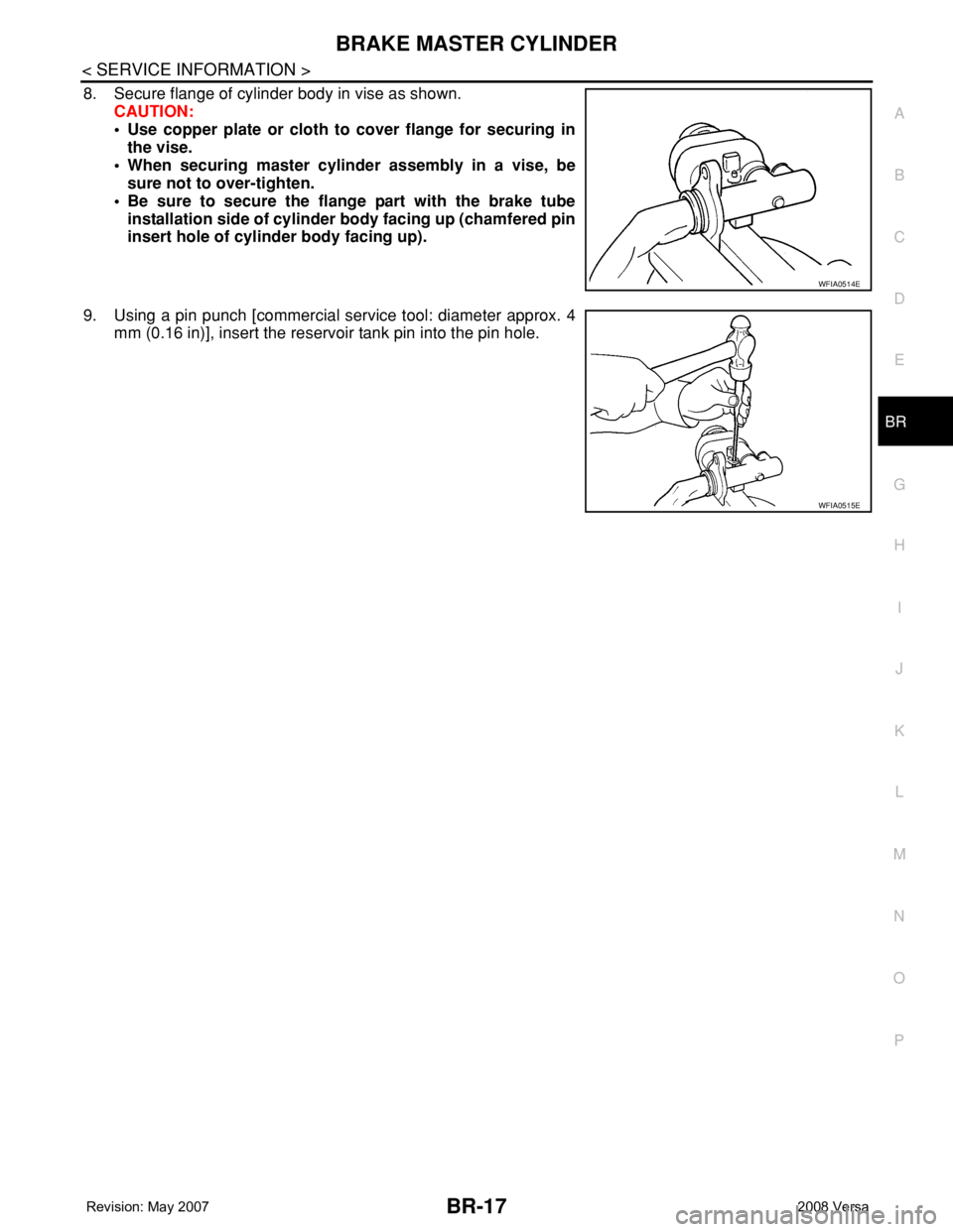
8. Secure flange of cylinder body in vise as shown.
CAUTION:
• Use copper plate or cloth to cover flange for securing in
the vise.
• When securing master cylinder assembly in a vise, be
sure not to over-tighten.
• Be sure to secure the flange part with the brake tube
installation side of cylinder body facing up (chamfered pin
insert hole of cylinder body facing up).
9. Using a pin punch [commercial service tool: diameter approx. 4
mm (0.16 in)], insert the reservoir tank pin into the pin hole.
WFIA0514E
WFIA0515E
Page 755 of 2771
BR-24
< SERVICE INFORMATION >
FRONT DISC BRAKE
CAUTION:
• Clean dust on caliper and brake pad with a vacuum dust collector. Do not blow with compressed air.
• While removing brake pad or cylinder body, do not depress brake pedal because piston will pop out.
• It is not necessary to remove torque member mounting bolts and brake hose except for disassembly
or replacement of caliper assembly. In this case, hang cylinder body with a wire so that brake hose is
not under tension.
• Do not damage piston boot.
• If any shim is subject to serious corrosion, replace it with a new one.
• Keep rotor free from brake fluid.
• When replacing brake pad, replace shim with a new one.
Removal and Installation of Brake PadINFOID:0000000001703798
REMOVAL
1. Remove tires from vehicle.
2. Remove sliding pin bolt (lower side).
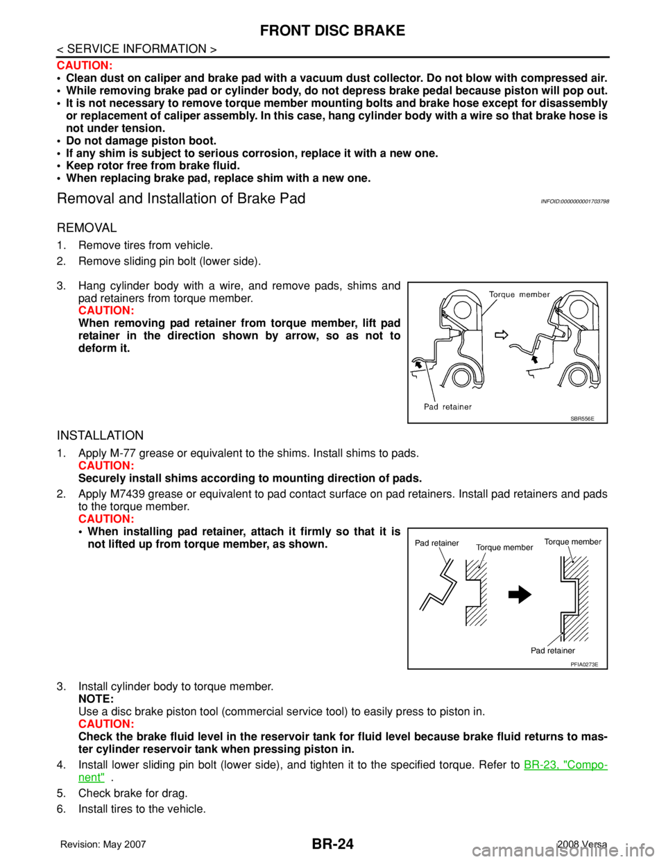
3. Hang cylinder body with a wire, and remove pads, shims and
pad retainers from torque member.
CAUTION:
When removing pad retainer from torque member, lift pad
retainer in the direction shown by arrow, so as not to
deform it.
INSTALLATION
1. Apply M-77 grease or equivalent to the shims. Install shims to pads.
CAUTION:
Securely install shims according to mounting direction of pads.
2. Apply M7439 grease or equivalent to pad contact surface on pad retainers. Install pad retainers and pads
to the torque member.
CAUTION:
• When installing pad retainer, attach it firmly so that it is
not lifted up from torque member, as shown.
3. Install cylinder body to torque member.
NOTE:
Use a disc brake piston tool (commercial service tool) to easily press to piston in.
CAUTION:
Check the brake fluid level in the reservoir tank for fluid level because brake fluid returns to mas-
ter cylinder reservoir tank when pressing piston in.
4. Install lower sliding pin bolt (lower side), and tighten it to the specified torque. Refer to BR-23, "
Compo-
nent" .
5. Check brake for drag.
6. Install tires to the vehicle.
SBR556E
PFIA0273E
Page 756 of 2771
FRONT DISC BRAKE
BR-25
< SERVICE INFORMATION >
C
D
E
G
H
I
J
K
L
MA
B
BR
N
O
P
Removal and Installation of Brake Caliper AssemblyINFOID:0000000001703799
REMOVAL
1. Remove tires from vehicle.
2. Secure disc rotor using wheel nuts.
CAUTION:
Put matching marks on wheel hub assembly and disc rotor, if it is necessary to remove disc rotor.
3. Drain brake fluid. Refer to BR-8, "
Drain and Refill" .
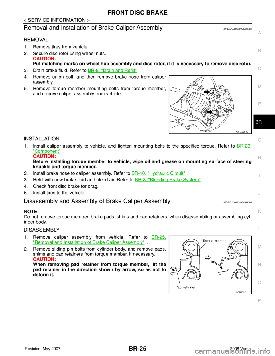
4. Remove union bolt, and then remove brake hose from caliper
assembly.
5. Remove torque member mounting bolts from torque member,
and remove caliper assembly from vehicle.
INSTALLATION
1. Install caliper assembly to vehicle, and tighten mounting bolts to the specified torque. Refer to BR-23,
"Component" .
CAUTION:
Before installing torque member to vehicle, wipe oil and grease on mounting surface of steering
knuckle and torque member.
2. Install brake hose to caliper assembly. Refer to BR-10, "
Hydraulic Circuit" .
3. Refill with new brake fluid and bleed air. Refer to BR-8, "
Bleeding Brake System" .
4. Check front disc brake for drag.
5. Install tires to the vehicle.
Disassembly and Assembly of Brake Caliper AssemblyINFOID:0000000001703800
NOTE:
Do not remove torque member, brake pads, shims and pad retainers, when disassembling or assembling cyl-
inder body.
DISASSEMBLY
1. Remove caliper assembly from vehicle. Refer to BR-25,
"Removal and Installation of Brake Caliper Assembly" .
2. Remove sliding pin bolts from cylinder body, and remove pads,
shims and pad retainers from torque member, if necessary.
CAUTION:
When removing pad retainer from torque member, lift the
pad retainer in the direction shown by arrow, so as not to
deform it.
WFIA0524E
SBR556E
Page 758 of 2771
FRONT DISC BRAKE
BR-27
< SERVICE INFORMATION >
C
D
E
G
H
I
J
K
L
MA
B
BR
N
O
P
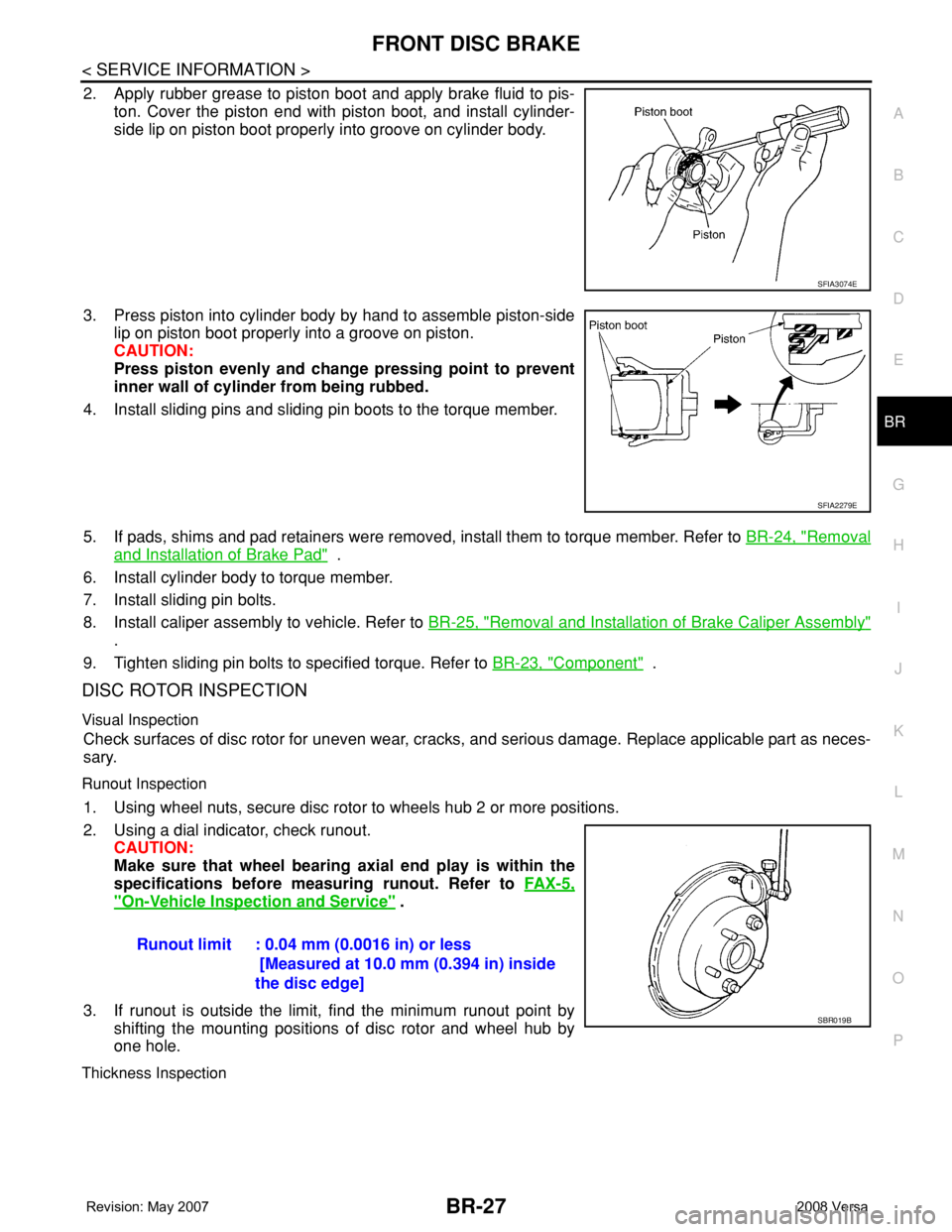
2. Apply rubber grease to piston boot and apply brake fluid to pis-
ton. Cover the piston end with piston boot, and install cylinder-
side lip on piston boot properly into groove on cylinder body.
3. Press piston into cylinder body by hand to assemble piston-side
lip on piston boot properly into a groove on piston.
CAUTION:
Press piston evenly and change pressing point to prevent
inner wall of cylinder from being rubbed.
4. Install sliding pins and sliding pin boots to the torque member.
5. If pads, shims and pad retainers were removed, install them to torque member. Refer to BR-24, "
Removal
and Installation of Brake Pad" .
6. Install cylinder body to torque member.
7. Install sliding pin bolts.
8. Install caliper assembly to vehicle. Refer to BR-25, "
Removal and Installation of Brake Caliper Assembly"
.
9. Tighten sliding pin bolts to specified torque. Refer to BR-23, "
Component" .
DISC ROTOR INSPECTION
Visual Inspection
Check surfaces of disc rotor for uneven wear, cracks, and serious damage. Replace applicable part as neces-
sary.
Runout Inspection
1. Using wheel nuts, secure disc rotor to wheels hub 2 or more positions.
2. Using a dial indicator, check runout.
CAUTION:
Make sure that wheel bearing axial end play is within the
specifications before measuring runout. Refer to FA X - 5 ,
"On-Vehicle Inspection and Service" .
3. If runout is outside the limit, find the minimum runout point by
shifting the mounting positions of disc rotor and wheel hub by
one hole.
Thickness Inspection
SFIA3074E
SFIA2279E
Runout limit : 0.04 mm (0.0016 in) or less
[Measured at 10.0 mm (0.394 in) inside
the disc edge]
SBR019B
Page 759 of 2771
BR-28
< SERVICE INFORMATION >
FRONT DISC BRAKE
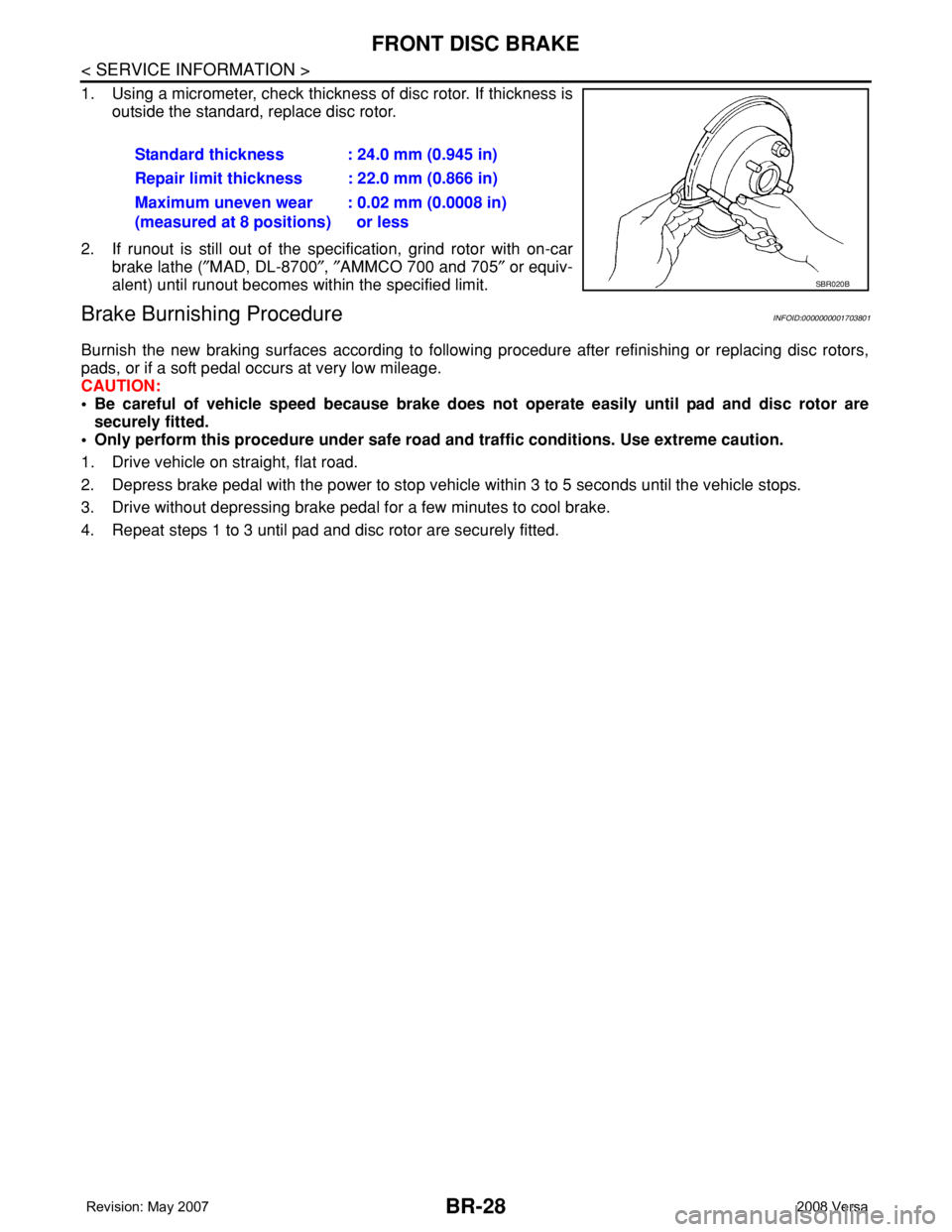
1. Using a micrometer, check thickness of disc rotor. If thickness is
outside the standard, replace disc rotor.
2. If runout is still out of the specification, grind rotor with on-car
brake lathe (″MAD, DL-8700″, ″AMMCO 700 and 705″ or equiv-
alent) until runout becomes within the specified limit.
Brake Burnishing ProcedureINFOID:0000000001703801
Burnish the new braking surfaces according to following procedure after refinishing or replacing disc rotors,
pads, or if a soft pedal occurs at very low mileage.
CAUTION:
• Be careful of vehicle speed because brake does not operate easily until pad and disc rotor are
securely fitted.
• Only perform this procedure under safe road and traffic conditions. Use extreme caution.
1. Drive vehicle on straight, flat road.
2. Depress brake pedal with the power to stop vehicle within 3 to 5 seconds until the vehicle stops.
3. Drive without depressing brake pedal for a few minutes to cool brake.
4. Repeat steps 1 to 3 until pad and disc rotor are securely fitted.Standard thickness : 24.0 mm (0.945 in)
Repair limit thickness : 22.0 mm (0.866 in)
Maximum uneven wear
(measured at 8 positions): 0.02 mm (0.0008 in)
or less
SBR020B
Page 784 of 2771
![NISSAN LATIO 2008 Service Repair Manual TROUBLE DIAGNOSIS
BRC-19
< SERVICE INFORMATION >[ABS]
C
D
E
G
H
I
J
K
L
MA
B
BRC
N
O
P
SELF-DIAGNOSIS
Description
If an error is detected in the system, the ABS warning lamp will turn on. In this case NISSAN LATIO 2008 Service Repair Manual TROUBLE DIAGNOSIS
BRC-19
< SERVICE INFORMATION >[ABS]
C
D
E
G
H
I
J
K
L
MA
B
BRC
N
O
P
SELF-DIAGNOSIS
Description
If an error is detected in the system, the ABS warning lamp will turn on. In this case](/manual-img/5/57360/w960_57360-783.png)
TROUBLE DIAGNOSIS
BRC-19
< SERVICE INFORMATION >[ABS]
C
D
E
G
H
I
J
K
L
MA
B
BRC
N
O
P
SELF-DIAGNOSIS
Description
If an error is detected in the system, the ABS warning lamp will turn on. In this case, perform self-diagnosis as
follows:
Operation Procedure
1. Turn ignition switch OFF.
2. Connect CONSULT-III to the data link connector.
3. Turn ignition switch ON.
4. Start engine and drive at approximately 30 km/h (19 MPH) or more for approximately 1 minute.
5. After stopping the vehicle, with the engine running, touch “ABS”, “SELF-DIAG RESULTS” in order on the
CONSULT-III screen.
6. The self-diagnostic results are displayed. (If necessary, the self-diagnostic results can be printed out by
touching “PRINT”.)
• When “NO DTC IS DETECTED” is displayed, check the ABS warning lamp.
7. Conduct the appropriate inspection from the display item list, and repair or replace the malfunctioning
component.
8. Start engine and drive at approximately 30 km/h (19 MPH) or more for approximately 1 minute.
CAUTION:
• When a wheel sensor “short-circuit” is detected, if the vehicle is not driven at 30 km/h (19 MPH)
for at least 1 minute, the ABS warning lamp will not turn off even if the malfunction is repaired.
9. Turn ignition switch OFF to prepare for erasing the memory.
10. Start the engine and touch “ABS”, “SELF-DIAG RESULTS”, “ERASE” in order on the CONSULT-III screen
to erase the error memory.
If “ABS” is not indicated, go to GI-36, "
CONSULT-III Data Link Connector (DLC) Circuit".
CAUTION:
If the error memory is not erased, re-conduct the operation from step 5.
11. For the final inspection, drive at approximately 30 km/h (19 MPH) or more for approximately 1 minute and
confirm that the ABS warning lamp is off.
Display Item List
FUNCTION TEST Conducted by CONSULT-III instead of a technician to determine whether each system is "OK" or "NG".
ECU PART NUMBER ABS actuator and electric unit (control unit) part number can be read. ABS diagnostic mode Description
Page 786 of 2771
![NISSAN LATIO 2008 Service Repair Manual TROUBLE DIAGNOSIS
BRC-21
< SERVICE INFORMATION >[ABS]
C
D
E
G
H
I
J
K
L
MA
B
BRC
N
O
P
Note 1: If wheel sensor 2 for each wheel is indicated, check ABS actuator and electric unit (control unit) power NISSAN LATIO 2008 Service Repair Manual TROUBLE DIAGNOSIS
BRC-21
< SERVICE INFORMATION >[ABS]
C
D
E
G
H
I
J
K
L
MA
B
BRC
N
O
P
Note 1: If wheel sensor 2 for each wheel is indicated, check ABS actuator and electric unit (control unit) power](/manual-img/5/57360/w960_57360-785.png)
TROUBLE DIAGNOSIS
BRC-21
< SERVICE INFORMATION >[ABS]
C
D
E
G
H
I
J
K
L
MA
B
BRC
N
O
P
Note 1: If wheel sensor 2 for each wheel is indicated, check ABS actuator and electric unit (control unit) power supply voltage in addition
to wheel sensor circuit check.
Note 2: If multiple malfunctions are detected including CAN communication line [U1000], perform diagnosis for CAN communication line
first.
DATA MONITOR
Operation Procedure
1. After turning OFF the ignition switch, connect CONSULT-III to the data link connector.
2. Touch “ABS”, “DATA MONITOR” in order on the CONSULT-III screen.
If “ABS” is not indicated, go to GI-36, "
CONSULT-III Data Link Connector (DLC) Circuit".
3. Return to the SELECT MONITOR ITEM screen, and touch “ECU INPUT SIGNALS”, “MAIN SIGNALS” or
“SELECTION FROM MENU”. Refer to the following information.
4. When “START” is touched, the data monitor screen is displayed.
Display Item List
MAIN RELAY
[ C 111 4 ]ABS actuator relay or circuit malfunction.BRC-26, "Actuator Mo-
tor, Motor Relay, and Cir-
cuit Inspection"
CAN COMM CIRCUIT
[U1000]• CAN communication line is open or shorted.
• ABS actuator and electric unit (control unit) internal malfunction
• Battery voltage for ECM is suddenly interrupted for approxi-
mately 0.5 second or more.BRC-28, "CAN Commu-
nication System Inspec-
tion" (Note 2) Self-diagnostic item Malfunction detecting condition Check system
Item
(Unit)Data monitor item selection
Remarks
ECU INPUT
SIGNALSMAIN
SIGNALSSELECTION
FROM MENU
FR RH SENSOR
(km/h, MPH)×××Wheel speed calculated by front RH
wheel sensor signal is displayed.
FR LH SENSOR
(km/h, MPH)×××Wheel speed calculated by front LH
wheel sensor signal is displayed.
RR RH SENSOR
(km/h, MPH)×××Wheel speed calculated by rear RH
wheel sensor signal is displayed.
RR LH SENSOR
(km/h, MPH)×××Wheel speed calculated by rear LH
wheel sensor signal is displayed.
BATTERY VOLT
(V)×××Voltage supplied to ABS actuator
and electric unit (control unit) is dis-
played.
STOP LAMP SW
(ON/OFF)×××Stop lamp switch (ON/OFF) status is
displayed.
ABS WARN LAMP
(ON/OFF)–××ABS warning lamp (ON/OFF) status
is displayed.
FR LH IN SOL
(ON/OFF)–××Front LH IN ABS solenoid (ON/OFF)
status is displayed.
FR LH OUT SOL
(ON/OFF)–××Front LH OUT ABS solenoid (ON/
OFF) status is displayed.
FR RH IN SOL
(ON/OFF)–××Front RH IN ABS solenoid (ON/
OFF) status is displayed.
FR RH OUT SOL
(ON/OFF)–××Front RH OUT ABS solenoid (ON/
OFF) status is displayed.
RR LH IN SOL
(ON/OFF)–××Rear LH IN ABS solenoid (ON/OFF)
status is displayed.
RR LH OUT SOL
(ON/OFF)–××Rear LH OUT ABS solenoid (ON/
OFF) status is displayed.
Page 787 of 2771
![NISSAN LATIO 2008 Service Repair Manual BRC-22
< SERVICE INFORMATION >[ABS]
TROUBLE DIAGNOSIS
×: Applicable
–: Not applicable
ACTIVE TEST
CAUTION:
• Do not perform active test while driving.
• Make sure to completely bleed air from t NISSAN LATIO 2008 Service Repair Manual BRC-22
< SERVICE INFORMATION >[ABS]
TROUBLE DIAGNOSIS
×: Applicable
–: Not applicable
ACTIVE TEST
CAUTION:
• Do not perform active test while driving.
• Make sure to completely bleed air from t](/manual-img/5/57360/w960_57360-786.png)
BRC-22
< SERVICE INFORMATION >[ABS]
TROUBLE DIAGNOSIS
×: Applicable
–: Not applicable
ACTIVE TEST
CAUTION:
• Do not perform active test while driving.
• Make sure to completely bleed air from the brake system.
• The ABS and brake warning lamps turn on during the active test.
Operation Procedure
1. Connect the CONSULT-III to the data link connector and start the engine.
2. Touch “ABS”.
If “ABS” is not indicated, go to GI-36, "
CONSULT-III Data Link Connector (DLC) Circuit".
3. Touch “ACTIVE TEST”.
4. The SELECT TEST ITEM screen is displayed.
5. Touch necessary test item.
6. With the “MAIN SIGNALS” display selected, touch “START”.
7. The Active Test screen will be displayed, so conduct the following test.
Solenoid Valve Operation Chart
NOTE:
• If active test is performed with brake pedal depressed, pedal stroke may change. This is normal.
• “TEST IS STOPPED” is displayed approximately 10 seconds after operation starts.
• After “TEST IS STOPPED” is displayed, to perform test again, repeat Step 6.
ABS Motor
Touch “ON” and “OFF” on the screen. Check that ABS motor relay operates as shown in table below.
RR RH IN SOL
(ON/OFF)–××Rear RH IN ABS solenoid (ON/OFF)
status is displayed.
RR RH OUT SOL
(ON/OFF)–××Rear RH OUT ABS solenoid (ON/
OFF) status is displayed.
MOTOR RELAY
(ON/OFF)–××ABS motor relay signal (ON/OFF)
status is displayed.
ACTUATOR RLY
(ON/OFF)–××ABS actuator relay signal (ON/OFF)
status is displayed.
ABS FAIL SIG
(ON/OFF)––×ABS fail signal (ON/OFF) status is
displayed.
EBD FAIL SIG
(ON/OFF)––×EBD fail signal (ON/OFF) status is
displayed.
EBD SIGNAL
(ON/OFF)––×EBD operation (ON/OFF) status is
displayed.
ABS SIGNAL
(ON/OFF)––×ABS operation (ON/OFF) status is
displayed. Item
(Unit)Data monitor item selection
Remarks
ECU INPUT
SIGNALSMAIN
SIGNALSSELECTION
FROM MENU
TEST ITEM CONDITION JUDGEMENT
FR RH SOL
FR LH SOL
RR RH SOL
RR LH SOLIgnition switch is turned ON.Brake fluid pressure control operation
IN SOL OUT SOL
UP (Increase): OFF OFF
KEEP (Hold): ON OFF
DOWN (Decrease): ON ON