2008 NISSAN LATIO ECU
[x] Cancel search: ECUPage 801 of 2771
![NISSAN LATIO 2008 Service Repair Manual BRC-36
< SERVICE INFORMATION >[ABS]
ACTUATOR AND ELECTRIC UNIT (ASSEMBLY)
Installation is the reverse order of removal.
CAUTION:
After installing harness connector in the ABS actuator and electric uni NISSAN LATIO 2008 Service Repair Manual BRC-36
< SERVICE INFORMATION >[ABS]
ACTUATOR AND ELECTRIC UNIT (ASSEMBLY)
Installation is the reverse order of removal.
CAUTION:
After installing harness connector in the ABS actuator and electric uni](/manual-img/5/57360/w960_57360-800.png)
BRC-36
< SERVICE INFORMATION >[ABS]
ACTUATOR AND ELECTRIC UNIT (ASSEMBLY)
Installation is the reverse order of removal.
CAUTION:
After installing harness connector in the ABS actuator and electric unit (control unit), make sure con-
nector is securely locked.
Page 810 of 2771
CLUTCH MASTER CYLINDER
CL-9
< SERVICE INFORMATION >
D
E
F
G
H
I
J
K
L
MA
B
CL
N
O
P
CLUTCH MASTER CYLINDER
Removal and InstallationINFOID:0000000001703120
REMOVAL
1. Remove the battery, battery tray and brackets. Refer to SC-4.
2. Remove the air cleaner and air duct. Refer to EM-16
.
3. Use one of the following methods to remove hose from master cylinder.
• Drain clutch fluid from reservoir tank and remove hose.
• Remove hose from master cylinder. Immediately plug hose and reservoir tank to prevent clutch fluid
from dripping.
CAUTION:
Do not spill clutch fluid onto painted surfaces. If it spills, wipe up immediately and wash the
affected area with water.
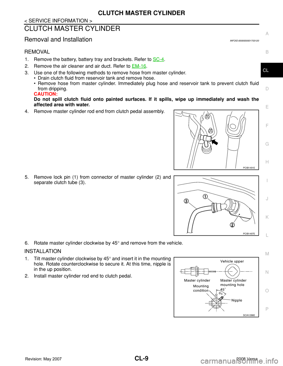
4. Remove master cylinder rod end from clutch pedal assembly.
5. Remove lock pin (1) from connector of master cylinder (2) and
separate clutch tube (3).
6. Rotate master cylinder clockwise by 45° and remove from the vehicle.
INSTALLATION
1. Tilt master cylinder clockwise by 45° and insert it in the mounting
hole. Rotate counterclockwise to secure it. At this time, nipple is
in the up position.
2. Install master cylinder rod end to clutch pedal.
PCIB1491E
PCIB1497E
SCIA1286E
Page 835 of 2771
CO-18
< SERVICE INFORMATION >
THERMOSTAT
• If out of the specification, replace thermostat.
INSTALLATION
Installation is in the reverse order of removal.
Thermostat
CAUTION:
Replace the rubber ring with a new one.
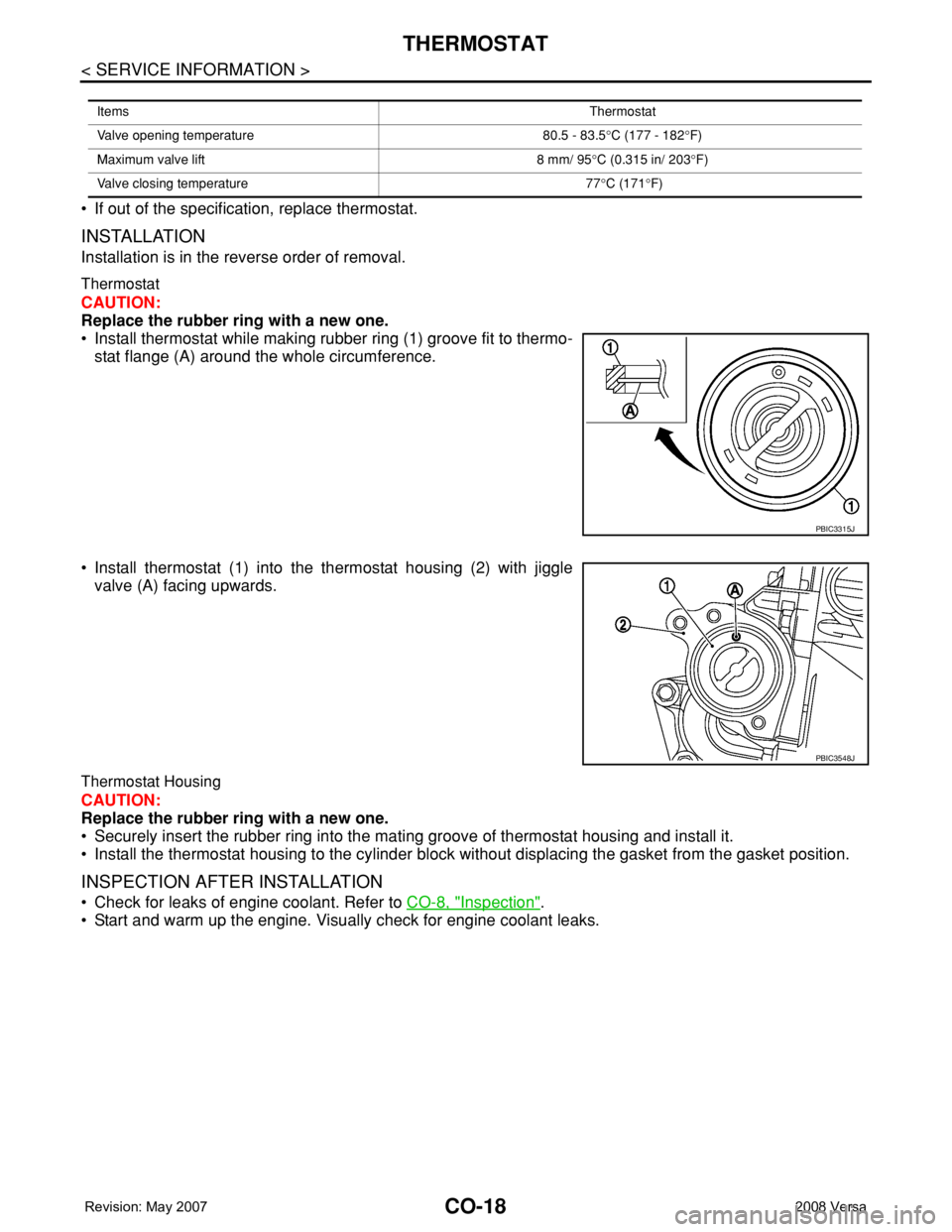
• Install thermostat while making rubber ring (1) groove fit to thermo-
stat flange (A) around the whole circumference.
• Install thermostat (1) into the thermostat housing (2) with jiggle
valve (A) facing upwards.
Thermostat Housing
CAUTION:
Replace the rubber ring with a new one.
• Securely insert the rubber ring into the mating groove of thermostat housing and install it.
• Install the thermostat housing to the cylinder block without displacing the gasket from the gasket position.
INSPECTION AFTER INSTALLATION
• Check for leaks of engine coolant. Refer to CO-8, "Inspection".
• Start and warm up the engine. Visually check for engine coolant leaks.
ItemsThermostat
Valve opening temperature 80.5 - 83.5°C (177 - 182°F)
Maximum valve lift 8 mm/ 95°C (0.315 in/ 203°F)
Valve closing temperature 77°C (171°F)
PBIC3315J
PBIC3548J
Page 847 of 2771

CVT-8
< SERVICE INFORMATION >
PRECAUTIONS
• Be sure to turn the ignition switch OFF and disconnect the battery cable from the negative terminal
before any repair or inspection work. The open/short circuit of related switches, sensors, solenoid
valves, etc. will cause the MIL to light up.
• Be sure to connect and lock the connectors securely after work. A loose (unlocked) connector will
cause the MIL to light up due to an open circuit. (Be sure the connector is free from water, grease,
dirt, bent terminals, etc.)
• Be sure to route and secure the harnesses properly after work. Interference of the harness with a
bracket, etc. may cause the MIL to light up due to a short circuit.
• Be sure to connect rubber tubes properly after work. A misconnected or disconnected rubber tube
may cause the MIL to light up due to a malfunction of the EVAP system or fuel injection system, etc.
• Be sure to erase the unnecessary malfunction information (repairs completed) from the TCM and
ECM before returning the vehicle to the customer.
Service After Replacing TCM and Transaxle AssemblyINFOID:0000000001703427
SERVICE AFTER REPLACING TCM AND TRANSAXLE ASSEMBLY
Perform the applicable service in the following sheet when replacing TCM or transaxle assembly
CAUTION:
• Do not start the engine until the service is completed.
• “A/T C/U POWER SUPPLY [P1701]” may be indicated soon after replacing TCM or transaxle assem-
bly (after erasing the memory at the pattern B). Restart the self-diagnosis after erasing the self-diag-
nosis result. Check that no error is detected.
NOTE:
Old unit means that the unit has been already used for another vehicle.
PATTERN A
1. Shift the selector lever to “P” position after replacing TCM. Turn the ignition switch ON.
2. Check that the shift position indicator in the combination meter turns ON (It indicates approximately 1 or 2
seconds after turning the ignition switch ON.)
• Check the following items if the shift position indicator does not turn ON. Repair or replace the shift posi-
tion indicator if necessary.
- The harness between TCM and ROM ASSY in the transaxle assembly is open or short.
- Cable disconnected, loosen, or bent from the connector housing.
PATTERN B
1. Turn the ignition switch ON after replacing each part.
2. Start engine.
CAUTION:
Do not start the driving.
3. Touch CONSULT-III screen in the order of “START (NISSAN BASED VHCL)”, “TRANSMISSION”, “DATA
MONITOR”, and “MAIN SIGNALS”.
4. Warm up the transaxle assembly until “ATFTEMPCOUNT” indicates 47 [approximately 20°C (68°F)] or
more. Turn the ignition switch OFF.
5. Turn the ignition switch ON.
CAUTION:
Do not start engine.
6. Select “SELF-DIAG RESULTS”.
7. Shift the selector lever to “R” position.
8. Depress slightly the accelerator pedal (Pedal angle: 2/8) while depressing the brake pedal.
9. Perform “ERASE”.
TCM CVT assemblyService pattern
Replace the new unit. Do not replace the unit. "PATTERN A"
Do not replace the unit. Replace the new or old unit.
"PATTERN B"
Replace the old unit.Do not replace the unit.
Replace the new or old unit.
Replace the new unit. Replace the new or old unit. "PATTERN C"
Page 849 of 2771
CVT-10
< SERVICE INFORMATION >
PRECAUTIONS
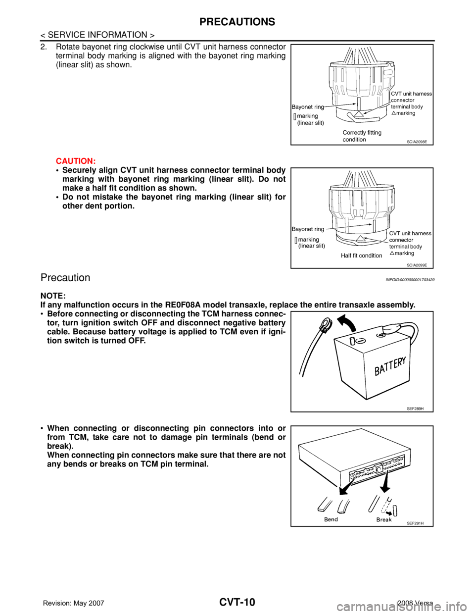
2. Rotate bayonet ring clockwise until CVT unit harness connector
terminal body marking is aligned with the bayonet ring marking
(linear slit) as shown.
CAUTION:
• Securely align CVT unit harness connector terminal body
marking with bayonet ring marking (linear slit). Do not
make a half fit condition as shown.
• Do not mistake the bayonet ring marking (linear slit) for
other dent portion.
PrecautionINFOID:0000000001703429
NOTE:
If any malfunction occurs in the RE0F08A model transaxle, replace the entire transaxle assembly.
•Before connecting or disconnecting the TCM harness connec-
tor, turn ignition switch OFF and disconnect negative battery
cable. Because battery voltage is applied to TCM even if igni-
tion switch is turned OFF.
•When connecting or disconnecting pin connectors into or
from TCM, take care not to damage pin terminals (bend or
break).
When connecting pin connectors make sure that there are not
any bends or breaks on TCM pin terminal.
SCIA2098E
SCIA2099E
SEF289H
SEF291H
Page 852 of 2771
CVT FLUID
CVT-13
< SERVICE INFORMATION >
D
E
F
G
H
I
J
K
L
MA
B
CVT
N
O
P
CVT FLUID
Checking CVT FluidINFOID:0000000001703433
FLUID LEVEL CHECK
Fluid level should be checked with the fluid warmed up to 50 to 80°C (122 to 176°F).
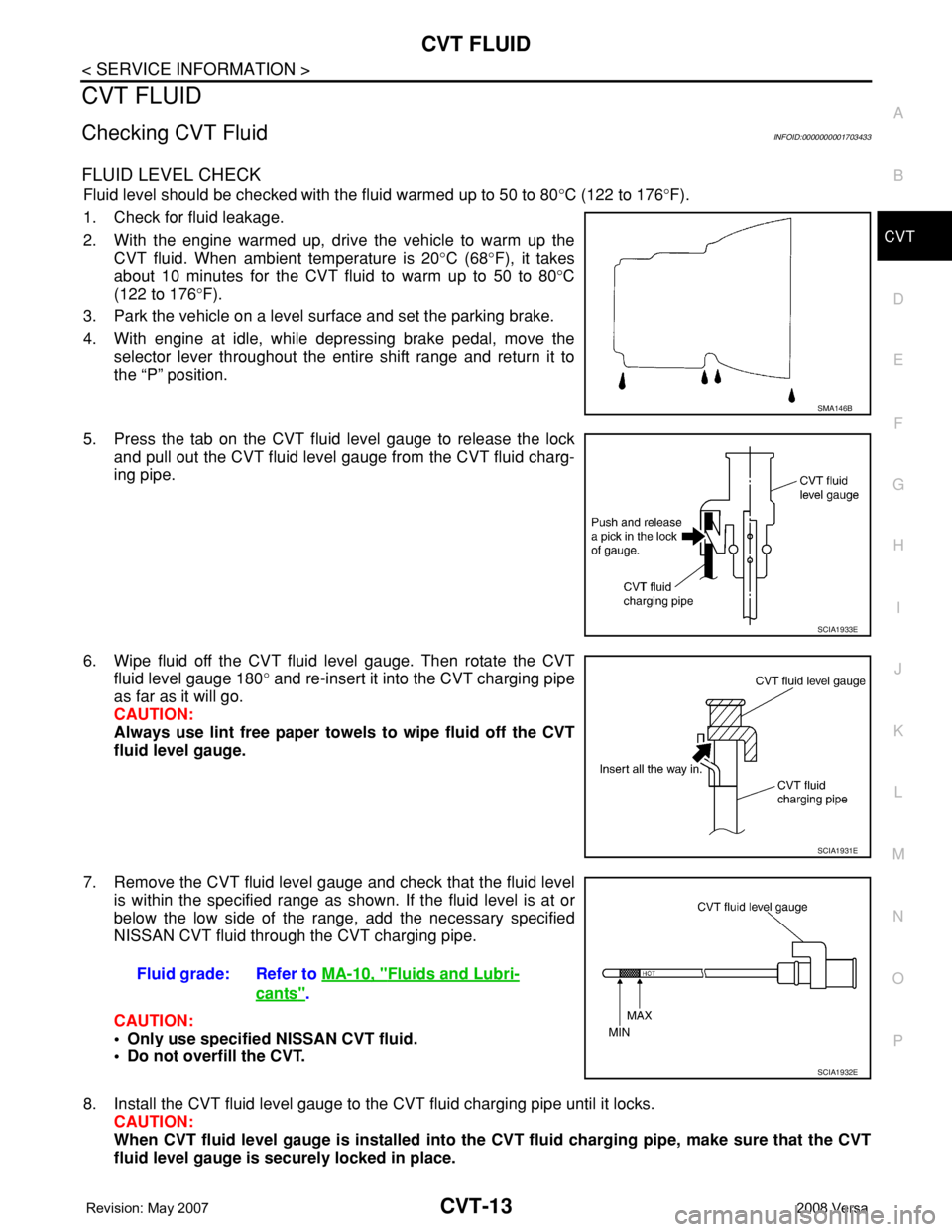
1. Check for fluid leakage.
2. With the engine warmed up, drive the vehicle to warm up the
CVT fluid. When ambient temperature is 20°C (68°F), it takes
about 10 minutes for the CVT fluid to warm up to 50 to 80°C
(122 to 176°F).
3. Park the vehicle on a level surface and set the parking brake.
4. With engine at idle, while depressing brake pedal, move the
selector lever throughout the entire shift range and return it to
the “P” position.
5. Press the tab on the CVT fluid level gauge to release the lock
and pull out the CVT fluid level gauge from the CVT fluid charg-
ing pipe.
6. Wipe fluid off the CVT fluid level gauge. Then rotate the CVT
fluid level gauge 180° and re-insert it into the CVT charging pipe
as far as it will go.
CAUTION:
Always use lint free paper towels to wipe fluid off the CVT
fluid level gauge.
7. Remove the CVT fluid level gauge and check that the fluid level
is within the specified range as shown. If the fluid level is at or
below the low side of the range, add the necessary specified
NISSAN CVT fluid through the CVT charging pipe.
CAUTION:
• Only use specified NISSAN CVT fluid.
• Do not overfill the CVT.
8. Install the CVT fluid level gauge to the CVT fluid charging pipe until it locks.
CAUTION:
When CVT fluid level gauge is installed into the CVT fluid charging pipe, make sure that the CVT
fluid level gauge is securely locked in place.
SMA146B
SCIA1933E
SCIA1931E
Fluid grade: Refer to MA-10, "Fluids and Lubri-
cants".
SCIA1932E
Page 863 of 2771
CVT-24
< SERVICE INFORMATION >
CVT SYSTEM
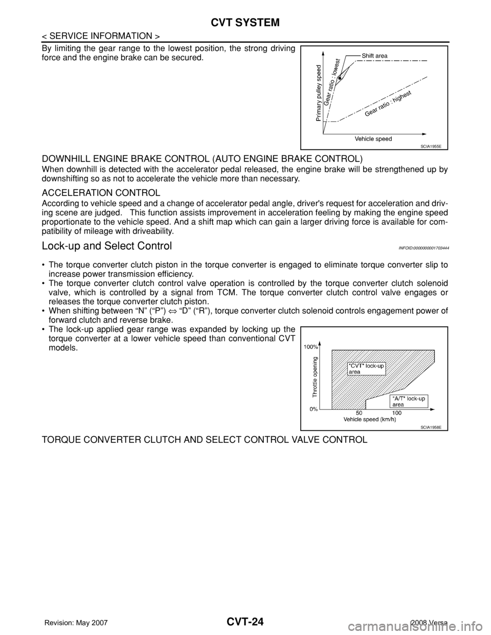
By limiting the gear range to the lowest position, the strong driving
force and the engine brake can be secured.
DOWNHILL ENGINE BRAKE CONTROL (AUTO ENGINE BRAKE CONTROL)
When downhill is detected with the accelerator pedal released, the engine brake will be strengthened up by
downshifting so as not to accelerate the vehicle more than necessary.
ACCELERATION CONTROL
According to vehicle speed and a change of accelerator pedal angle, driver's request for acceleration and driv-
ing scene are judged. This function assists improvement in acceleration feeling by making the engine speed
proportionate to the vehicle speed. And a shift map which can gain a larger driving force is available for com-
patibility of mileage with driveability.
Lock-up and Select ControlINFOID:0000000001703444
• The torque converter clutch piston in the torque converter is engaged to eliminate torque converter slip to
increase power transmission efficiency.
• The torque converter clutch control valve operation is controlled by the torque converter clutch solenoid
valve, which is controlled by a signal from TCM. The torque converter clutch control valve engages or
releases the torque converter clutch piston.
• When shifting between “N” (“P”) ⇔ “D” (“R”), torque converter clutch solenoid controls engagement power of
forward clutch and reverse brake.
• The lock-up applied gear range was expanded by locking up the
torque converter at a lower vehicle speed than conventional CVT
models.
TORQUE CONVERTER CLUTCH AND SELECT CONTROL VALVE CONTROL
SCIA1955E
SCIA1958E
Page 876 of 2771
TROUBLE DIAGNOSIS
CVT-37
< SERVICE INFORMATION >
D
E
F
G
H
I
J
K
L
MA
B
CVT
N
O
P
• Inspect for fluid leakage and check the fluid level. Refer to MA-19, "Checking CVT Fluid" .
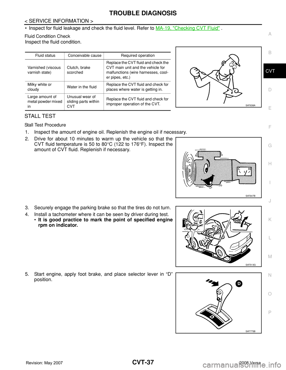
Fluid Condition Check
Inspect the fluid condition.
STALL TEST
Stall Test Procedure
1. Inspect the amount of engine oil. Replenish the engine oil if necessary.
2. Drive for about 10 minutes to warm up the vehicle so that the
CVT fluid temperature is 50 to 80°C (122 to 176°F). Inspect the
amount of CVT fluid. Replenish if necessary.
3. Securely engage the parking brake so that the tires do not turn.
4. Install a tachometer where it can be seen by driver during test.
•It is good practice to mark the point of specified engine
rpm on indicator.
5. Start engine, apply foot brake, and place selector lever in “D”
position.
Fluid status Conceivable cause Required operation
Varnished (viscous
varnish state)Clutch, brake
scorchedReplace the CVT fluid and check the
CVT main unit and the vehicle for
malfunctions (wire harnesses, cool-
er pipes, etc.)
Milky white or
cloudyWater in the fluidReplace the CVT fluid and check for
places where water is getting in.
Large amount of
metal powder mixed
inUnusual wear of
sliding parts within
CVTReplace the CVT fluid and check for
improper operation of the CVT.
SAT638A
SAT647B
SAT513G
SAT775B