2008 NISSAN LATIO ECU
[x] Cancel search: ECUPage 952 of 2771
DTC P0841 PRESSURE SENSOR FUNCTION
CVT-113
< SERVICE INFORMATION >
D
E
F
G
H
I
J
K
L
MA
B
CVT
N
O
P
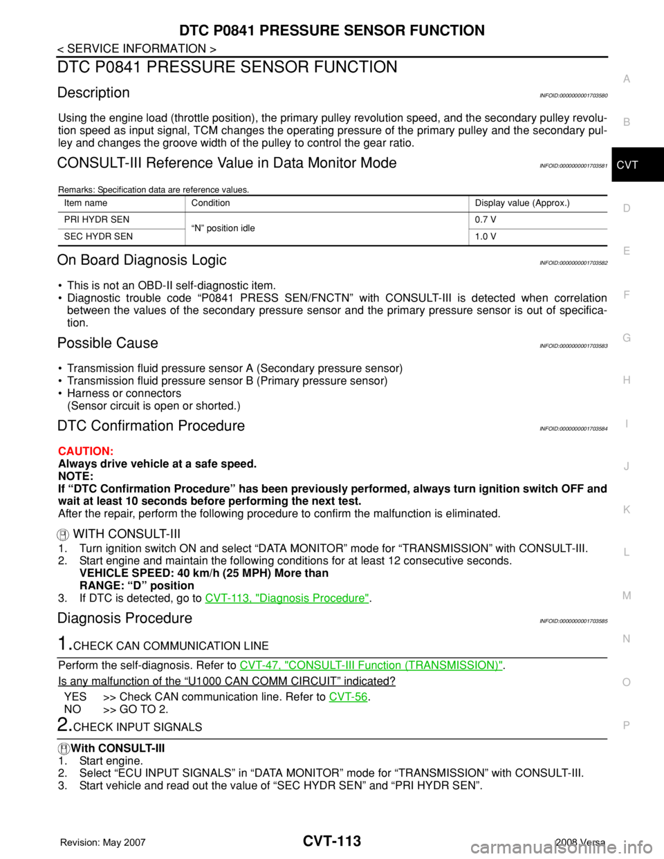
DTC P0841 PRESSURE SENSOR FUNCTION
DescriptionINFOID:0000000001703580
Using the engine load (throttle position), the primary pulley revolution speed, and the secondary pulley revolu-
tion speed as input signal, TCM changes the operating pressure of the primary pulley and the secondary pul-
ley and changes the groove width of the pulley to control the gear ratio.
CONSULT-III Reference Value in Data Monitor ModeINFOID:0000000001703581
Remarks: Specification data are reference values.
On Board Diagnosis LogicINFOID:0000000001703582
• This is not an OBD-II self-diagnostic item.
• Diagnostic trouble code “P0841 PRESS SEN/FNCTN” with CONSULT-III is detected when correlation
between the values of the secondary pressure sensor and the primary pressure sensor is out of specifica-
tion.
Possible CauseINFOID:0000000001703583
• Transmission fluid pressure sensor A (Secondary pressure sensor)
• Transmission fluid pressure sensor B (Primary pressure sensor)
• Harness or connectors
(Sensor circuit is open or shorted.)
DTC Confirmation ProcedureINFOID:0000000001703584
CAUTION:
Always drive vehicle at a safe speed.
NOTE:
If “DTC Confirmation Procedure” has been previously performed, always turn ignition switch OFF and
wait at least 10 seconds before performing the next test.
After the repair, perform the following procedure to confirm the malfunction is eliminated.
WITH CONSULT-III
1. Turn ignition switch ON and select “DATA MONITOR” mode for “TRANSMISSION” with CONSULT-III.
2. Start engine and maintain the following conditions for at least 12 consecutive seconds.
VEHICLE SPEED: 40 km/h (25 MPH) More than
RANGE: “D” position
3. If DTC is detected, go to CVT-113, "
Diagnosis Procedure".
Diagnosis ProcedureINFOID:0000000001703585
1.CHECK CAN COMMUNICATION LINE
Perform the self-diagnosis. Refer to CVT-47, "
CONSULT-III Function (TRANSMISSION)".
Is any malfunction of the
“U1000 CAN COMM CIRCUIT” indicated?
YES >> Check CAN communication line. Refer to CVT-56.
NO >> GO TO 2.
2.CHECK INPUT SIGNALS
With CONSULT-III
1. Start engine.
2. Select “ECU INPUT SIGNALS” in “DATA MONITOR” mode for “TRANSMISSION” with CONSULT-III.
3. Start vehicle and read out the value of “SEC HYDR SEN” and “PRI HYDR SEN”.
Item name Condition Display value (Approx.)
PRI HYDR SEN
“N” position idle0.7 V
SEC HYDR SEN1.0 V
Page 954 of 2771
DTC P0845 TRANSMISSION FLUID PRESSURE SENSOR B CIRCUIT (PRI
PRESSURE SENSOR)
CVT-115
< SERVICE INFORMATION >
D
E
F
G
H
I
J
K
L
MA
B
CVT
N
O
P
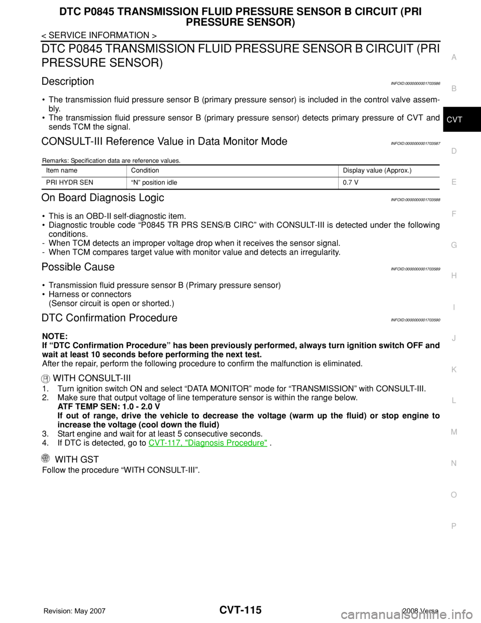
DTC P0845 TRANSMISSION FLUID PRESSURE SENSOR B CIRCUIT (PRI
PRESSURE SENSOR)
DescriptionINFOID:0000000001703586
• The transmission fluid pressure sensor B (primary pressure sensor) is included in the control valve assem-
bly.
• The transmission fluid pressure sensor B (primary pressure sensor) detects primary pressure of CVT and
sends TCM the signal.
CONSULT-III Reference Value in Data Monitor ModeINFOID:0000000001703587
Remarks: Specification data are reference values.
On Board Diagnosis LogicINFOID:0000000001703588
• This is an OBD-II self-diagnostic item.
• Diagnostic trouble code “P0845 TR PRS SENS/B CIRC” with CONSULT-III is detected under the following
conditions.
- When TCM detects an improper voltage drop when it receives the sensor signal.
- When TCM compares target value with monitor value and detects an irregularity.
Possible CauseINFOID:0000000001703589
• Transmission fluid pressure sensor B (Primary pressure sensor)
• Harness or connectors
(Sensor circuit is open or shorted.)
DTC Confirmation ProcedureINFOID:0000000001703590
NOTE:
If “DTC Confirmation Procedure” has been previously performed, always turn ignition switch OFF and
wait at least 10 seconds before performing the next test.
After the repair, perform the following procedure to confirm the malfunction is eliminated.
WITH CONSULT-III
1. Turn ignition switch ON and select “DATA MONITOR” mode for “TRANSMISSION” with CONSULT-III.
2. Make sure that output voltage of line temperature sensor is within the range below.
ATF TEMP SEN: 1.0 - 2.0 V
If out of range, drive the vehicle to decrease the voltage (warm up the fluid) or stop engine to
increase the voltage (cool down the fluid)
3. Start engine and wait for at least 5 consecutive seconds.
4. If DTC is detected, go to CVT-117, "
Diagnosis Procedure" .
WITH GST
Follow the procedure “WITH CONSULT-III”.
Item name Condition Display value (Approx.)
PRI HYDR SEN “N” position idle 0.7 V
Page 956 of 2771
DTC P0845 TRANSMISSION FLUID PRESSURE SENSOR B CIRCUIT (PRI
PRESSURE SENSOR)
CVT-117
< SERVICE INFORMATION >
D
E
F
G
H
I
J
K
L
MA
B
CVT
N
O
P
Diagnosis ProcedureINFOID:0000000001703592
1.CHECK INPUT SIGNAL
With CONSULT-III
1. Start engine.
2. Select “ECU INPUT SIGNALS” in “DATA MONITOR” mode for “TRANSMISSION” with CONSULT-III.
3. Start vehicle and read out the value of “PRI HYDR SEN”.
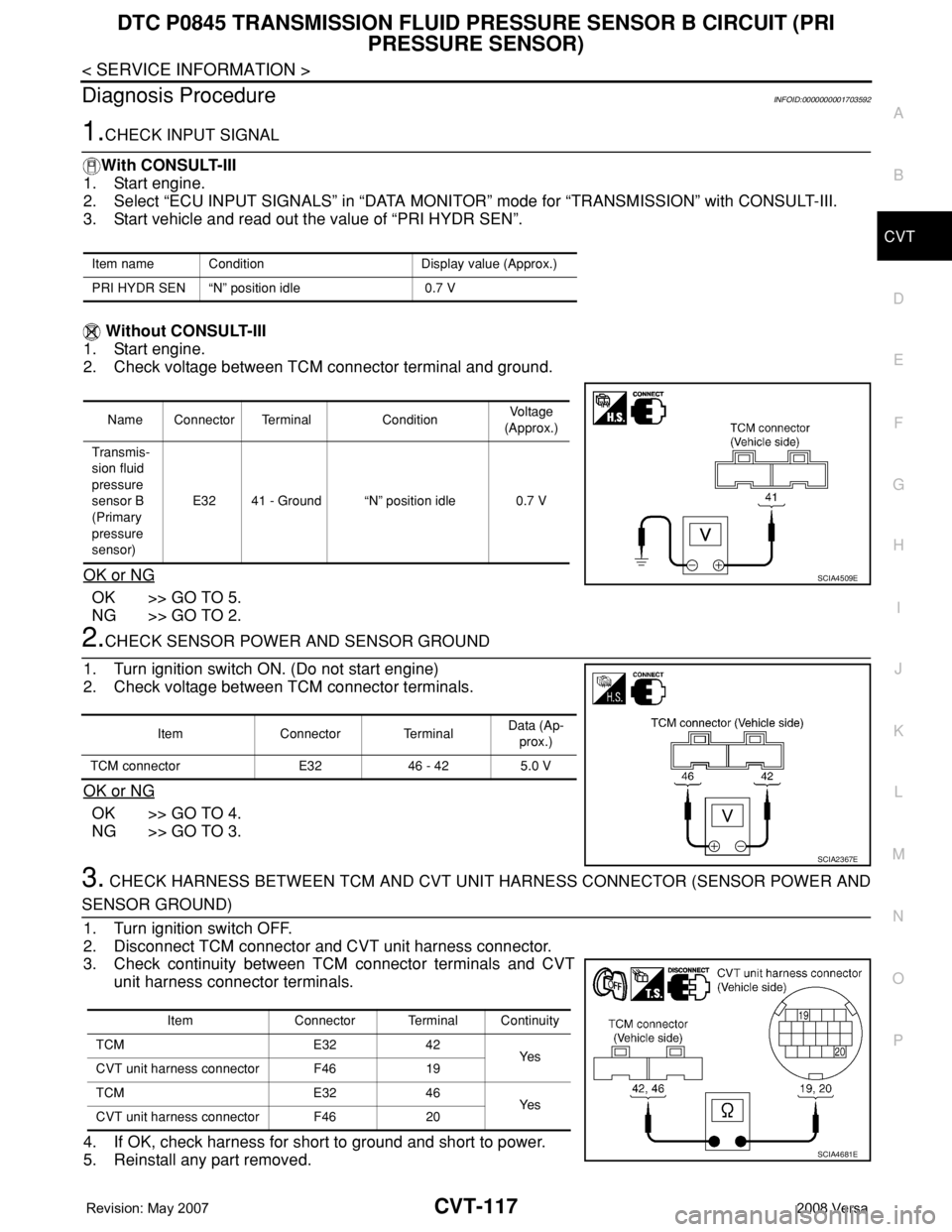
Without CONSULT-III
1. Start engine.
2. Check voltage between TCM connector terminal and ground.
OK or NG
OK >> GO TO 5.
NG >> GO TO 2.
2.CHECK SENSOR POWER AND SENSOR GROUND
1. Turn ignition switch ON. (Do not start engine)
2. Check voltage between TCM connector terminals.
OK or NG
OK >> GO TO 4.
NG >> GO TO 3.
3. CHECK HARNESS BETWEEN TCM AND CVT UNIT HARNESS CONNECTOR (SENSOR POWER AND
SENSOR GROUND)
1. Turn ignition switch OFF.
2. Disconnect TCM connector and CVT unit harness connector.
3. Check continuity between TCM connector terminals and CVT
unit harness connector terminals.
4. If OK, check harness for short to ground and short to power.
5. Reinstall any part removed.
Item name Condition Display value (Approx.)
PRI HYDR SEN “N” position idle 0.7 V
Name Connector Terminal ConditionVoltage
(Approx.)
Transmis-
sion fluid
pressure
sensor B
(Primary
pressure
sensor)E32 41 - Ground “N” position idle 0.7 V
SCIA4509E
Item Connector TerminalData (Ap-
prox.)
TCM connector E32 46 - 42 5.0 V
SCIA2367E
Item Connector Terminal Continuity
TCM E32 42
Ye s
CVT unit harness connector F46 19
TCM E32 46
Ye s
CVT unit harness connector F46 20
SCIA4681E
Page 958 of 2771
DTC P0868 SECONDARY PRESSURE DOWN
CVT-119
< SERVICE INFORMATION >
D
E
F
G
H
I
J
K
L
MA
B
CVT
N
O
P
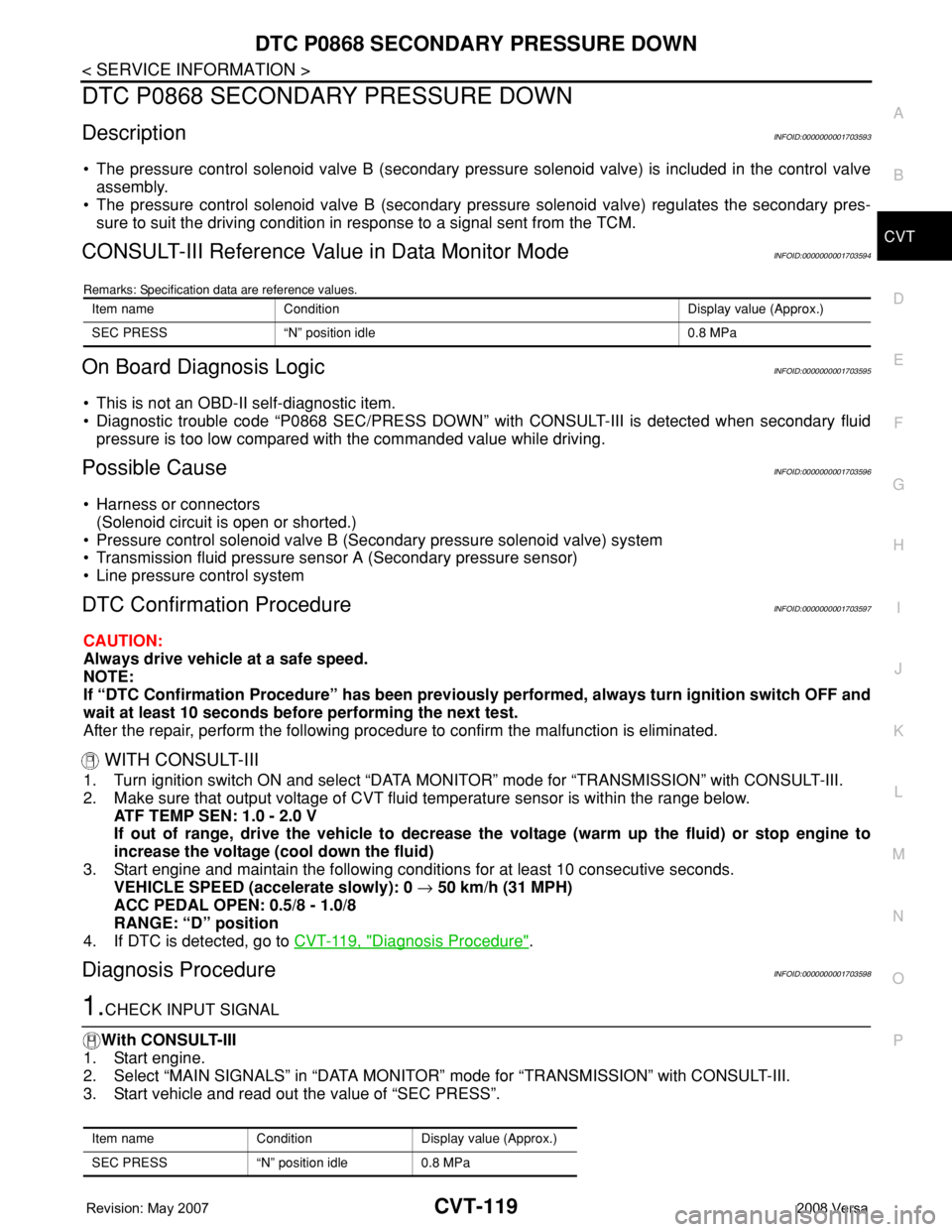
DTC P0868 SECONDARY PRESSURE DOWN
DescriptionINFOID:0000000001703593
• The pressure control solenoid valve B (secondary pressure solenoid valve) is included in the control valve
assembly.
• The pressure control solenoid valve B (secondary pressure solenoid valve) regulates the secondary pres-
sure to suit the driving condition in response to a signal sent from the TCM.
CONSULT-III Reference Value in Data Monitor ModeINFOID:0000000001703594
Remarks: Specification data are reference values.
On Board Diagnosis LogicINFOID:0000000001703595
• This is not an OBD-II self-diagnostic item.
• Diagnostic trouble code “P0868 SEC/PRESS DOWN” with CONSULT-III is detected when secondary fluid
pressure is too low compared with the commanded value while driving.
Possible CauseINFOID:0000000001703596
• Harness or connectors
(Solenoid circuit is open or shorted.)
• Pressure control solenoid valve B (Secondary pressure solenoid valve) system
• Transmission fluid pressure sensor A (Secondary pressure sensor)
• Line pressure control system
DTC Confirmation ProcedureINFOID:0000000001703597
CAUTION:
Always drive vehicle at a safe speed.
NOTE:
If “DTC Confirmation Procedure” has been previously performed, always turn ignition switch OFF and
wait at least 10 seconds before performing the next test.
After the repair, perform the following procedure to confirm the malfunction is eliminated.
WITH CONSULT-III
1. Turn ignition switch ON and select “DATA MONITOR” mode for “TRANSMISSION” with CONSULT-III.
2. Make sure that output voltage of CVT fluid temperature sensor is within the range below.
ATF TEMP SEN: 1.0 - 2.0 V
If out of range, drive the vehicle to decrease the voltage (warm up the fluid) or stop engine to
increase the voltage (cool down the fluid)
3. Start engine and maintain the following conditions for at least 10 consecutive seconds.
VEHICLE SPEED (accelerate slowly): 0 → 50 km/h (31 MPH)
ACC PEDAL OPEN: 0.5/8 - 1.0/8
RANGE: “D” position
4. If DTC is detected, go to CVT-119, "
Diagnosis Procedure".
Diagnosis ProcedureINFOID:0000000001703598
1.CHECK INPUT SIGNAL
With CONSULT-III
1. Start engine.
2. Select “MAIN SIGNALS” in “DATA MONITOR” mode for “TRANSMISSION” with CONSULT-III.
3. Start vehicle and read out the value of “SEC PRESS”.
Item name Condition Display value (Approx.)
SEC PRESS “N” position idle 0.8 MPa
Item name Condition Display value (Approx.)
SEC PRESS “N” position idle 0.8 MPa
Page 960 of 2771
DTC P1701 TRANSMISSION CONTROL MODULE (POWER SUPPLY)
CVT-121
< SERVICE INFORMATION >
D
E
F
G
H
I
J
K
L
MA
B
CVT
N
O
P
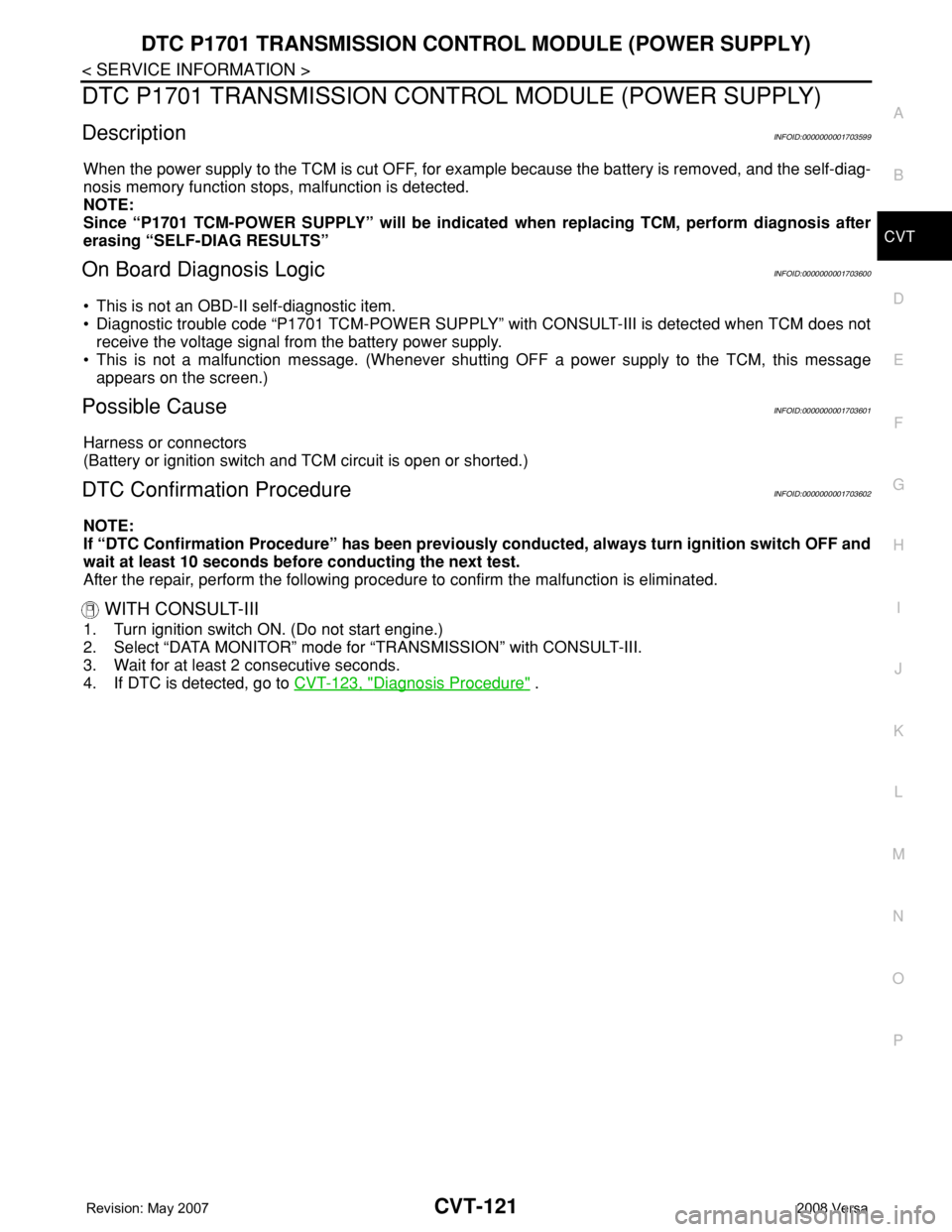
DTC P1701 TRANSMISSION CONTROL MODULE (POWER SUPPLY)
DescriptionINFOID:0000000001703599
When the power supply to the TCM is cut OFF, for example because the battery is removed, and the self-diag-
nosis memory function stops, malfunction is detected.
NOTE:
Since “P1701 TCM-POWER SUPPLY” will be indicated when replacing TCM, perform diagnosis after
erasing “SELF-DIAG RESULTS”
On Board Diagnosis LogicINFOID:0000000001703600
• This is not an OBD-II self-diagnostic item.
• Diagnostic trouble code “P1701 TCM-POWER SUPPLY” with CONSULT-III is detected when TCM does not
receive the voltage signal from the battery power supply.
• This is not a malfunction message. (Whenever shutting OFF a power supply to the TCM, this message
appears on the screen.)
Possible CauseINFOID:0000000001703601
Harness or connectors
(Battery or ignition switch and TCM circuit is open or shorted.)
DTC Confirmation ProcedureINFOID:0000000001703602
NOTE:
If “DTC Confirmation Procedure” has been previously conducted, always turn ignition switch OFF and
wait at least 10 seconds before conducting the next test.
After the repair, perform the following procedure to confirm the malfunction is eliminated.
WITH CONSULT-III
1. Turn ignition switch ON. (Do not start engine.)
2. Select “DATA MONITOR” mode for “TRANSMISSION” with CONSULT-III.
3. Wait for at least 2 consecutive seconds.
4. If DTC is detected, go to CVT-123, "
Diagnosis Procedure" .
Page 964 of 2771
DTC P1705 THROTTLE POSITION SENSOR
CVT-125
< SERVICE INFORMATION >
D
E
F
G
H
I
J
K
L
MA
B
CVT
N
O
P
DTC P1705 THROTTLE POSITION SENSOR
DescriptionINFOID:0000000001703605
Electric throttle control actuator consists of throttle control motor, accelerator pedal position sensor, throttle
position sensor etc. The actuator sends a signal to the ECM, and ECM sends the signal to TCM with CAN
communication.
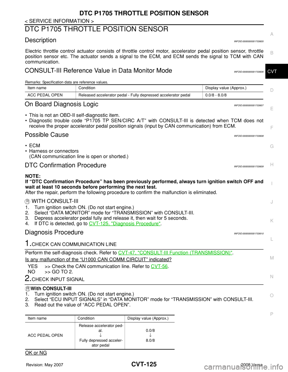
CONSULT-III Reference Value in Data Monitor ModeINFOID:0000000001703606
Remarks: Specification data are reference values.
On Board Diagnosis LogicINFOID:0000000001703607
• This is not an OBD-II self-diagnostic item.
• Diagnostic trouble code “P1705 TP SEN/CIRC A/T” with CONSULT-III is detected when TCM does not
receive the proper accelerator pedal position signals (input by CAN communication) from ECM.
Possible CauseINFOID:0000000001703608
•ECM
• Harness or connectors
(CAN communication line is open or shorted.)
DTC Confirmation ProcedureINFOID:0000000001703609
NOTE:
If “DTC Confirmation Procedure” has been previously performed, always turn ignition switch OFF and
wait at least 10 seconds before performing the next test.
After the repair, perform the following procedure to confirm the malfunction is eliminated.
WITH CONSULT-III
1. Turn ignition switch ON. (Do not start engine.)
2. Select “DATA MONITOR” mode for “TRANSMISSION” with CONSULT-III.
3. Depress accelerator pedal fully and release it, then wait for 5 seconds.
4. If DTC is detected, go to CVT-125, "
Diagnosis Procedure".
Diagnosis ProcedureINFOID:0000000001703610
1.CHECK CAN COMMUNICATION LINE
Perform the self-diagnosis check. Refer to CVT-47, "
CONSULT-III Function (TRANSMISSION)".
Is any malfunction of the
“U1000 CAN COMM CIRCUIT” indicated?
YES >> Check the CAN communication line. Refer to CVT-56.
NO >> GO TO 2.
2.CHECK INPUT SIGNAL
With CONSULT-III
1. Turn ignition switch ON. (Do not start engine.)
2. Select “ECU INPUT SIGNALS” in “DATA MONITOR” mode for “TRANSMISSION” with CONSULT-III.
3. Read out the value of “ACC PEDAL OPEN”.
OK or NG
Item name Condition Display value (Approx.)
ACC PEDAL OPEN Released accelerator pedal - Fully depressed accelerator pedal 0.0/8 - 8.0/8
Item name Condition Display value (Approx.)
ACC PEDAL OPEN Release accelerator ped-
al.
↓
Fully depressed acceler-
ator pedal0.0/8
↓
8.0/8
Page 966 of 2771
DTC P1722 ESTM VEHICLE SPEED SIGNAL
CVT-127
< SERVICE INFORMATION >
D
E
F
G
H
I
J
K
L
MA
B
CVT
N
O
P
DTC P1722 ESTM VEHICLE SPEED SIGNAL
DescriptionINFOID:0000000001703611
The vehicle speed signal is transmitted from ABS actuator and electric unit (control unit) to TCM by CAN com-
munication line.
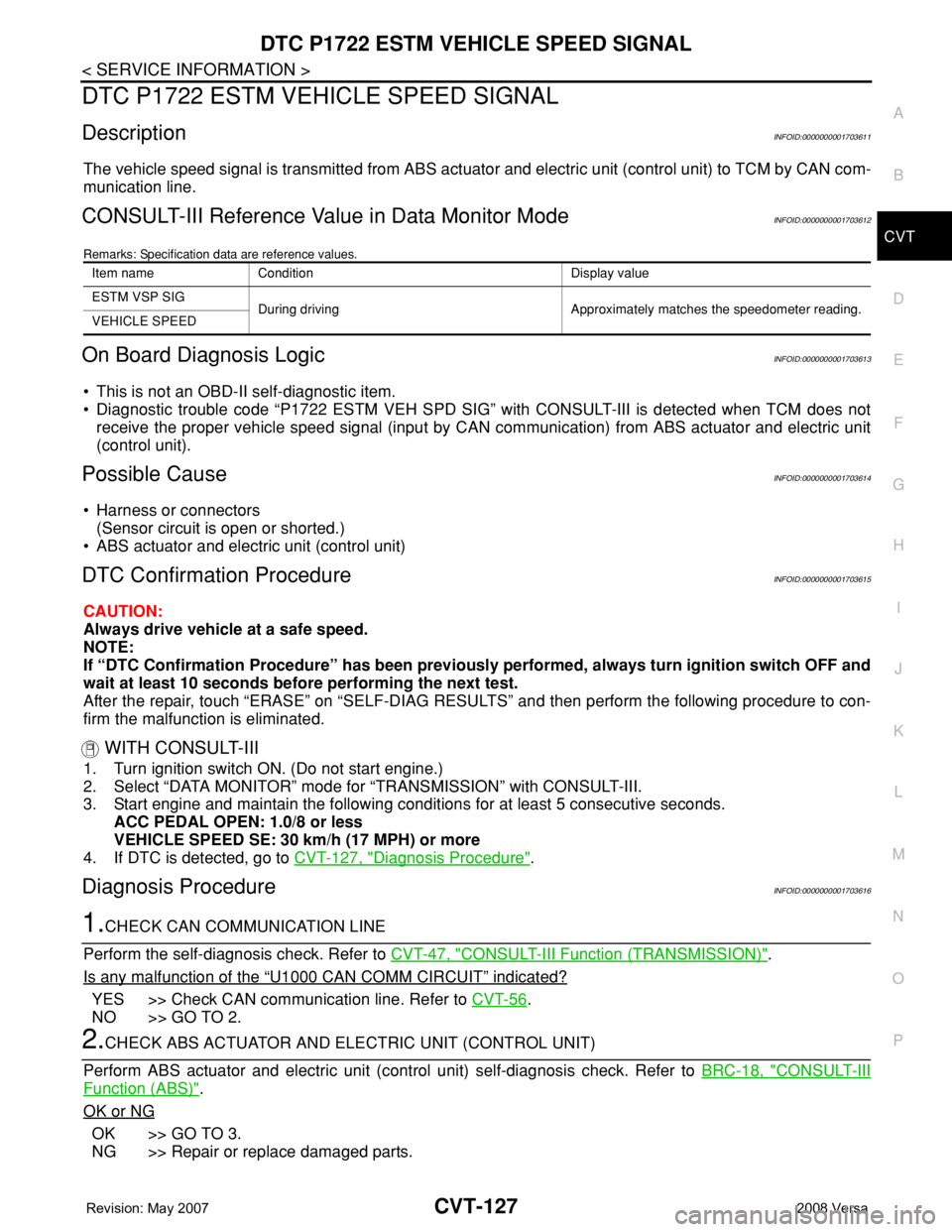
CONSULT-III Reference Value in Data Monitor ModeINFOID:0000000001703612
Remarks: Specification data are reference values.
On Board Diagnosis LogicINFOID:0000000001703613
• This is not an OBD-II self-diagnostic item.
• Diagnostic trouble code “P1722 ESTM VEH SPD SIG” with CONSULT-III is detected when TCM does not
receive the proper vehicle speed signal (input by CAN communication) from ABS actuator and electric unit
(control unit).
Possible CauseINFOID:0000000001703614
• Harness or connectors
(Sensor circuit is open or shorted.)
• ABS actuator and electric unit (control unit)
DTC Confirmation ProcedureINFOID:0000000001703615
CAUTION:
Always drive vehicle at a safe speed.
NOTE:
If “DTC Confirmation Procedure” has been previously performed, always turn ignition switch OFF and
wait at least 10 seconds before performing the next test.
After the repair, touch “ERASE” on “SELF-DIAG RESULTS” and then perform the following procedure to con-
firm the malfunction is eliminated.
WITH CONSULT-III
1. Turn ignition switch ON. (Do not start engine.)
2. Select “DATA MONITOR” mode for “TRANSMISSION” with CONSULT-III.
3. Start engine and maintain the following conditions for at least 5 consecutive seconds.
ACC PEDAL OPEN: 1.0/8 or less
VEHICLE SPEED SE: 30 km/h (17 MPH) or more
4. If DTC is detected, go to CVT-127, "
Diagnosis Procedure".
Diagnosis ProcedureINFOID:0000000001703616
1.CHECK CAN COMMUNICATION LINE
Perform the self-diagnosis check. Refer to CVT-47, "
CONSULT-III Function (TRANSMISSION)".
Is any malfunction of the
“U1000 CAN COMM CIRCUIT” indicated?
YES >> Check CAN communication line. Refer to CVT-56.
NO >> GO TO 2.
2.CHECK ABS ACTUATOR AND ELECTRIC UNIT (CONTROL UNIT)
Perform ABS actuator and electric unit (control unit) self-diagnosis check. Refer to BRC-18, "
CONSULT-III
Function (ABS)".
OK or NG
OK >> GO TO 3.
NG >> Repair or replace damaged parts.
Item name Condition Display value
ESTM VSP SIG
During driving Approximately matches the speedometer reading.
VEHICLE SPEED
Page 968 of 2771
DTC P1723 CVT SPEED SENSOR FUNCTION
CVT-129
< SERVICE INFORMATION >
D
E
F
G
H
I
J
K
L
MA
B
CVT
N
O
P
DTC P1723 CVT SPEED SENSOR FUNCTION
DescriptionINFOID:0000000001703617
• The input speed sensor (primary speed sensor) is included in the control valve assembly.
• The vehicle speed sensor CVT [output speed sensor (secondary speed sensor)] detects the revolution of the
idler gear and generates a pulse signal. The pulse signal is sent to the TCM, which converts it into vehicle
speed.
• The input speed sensor (primary speed sensor) detects the primary pulley revolution speed and sends a sig-
nal to the TCM.
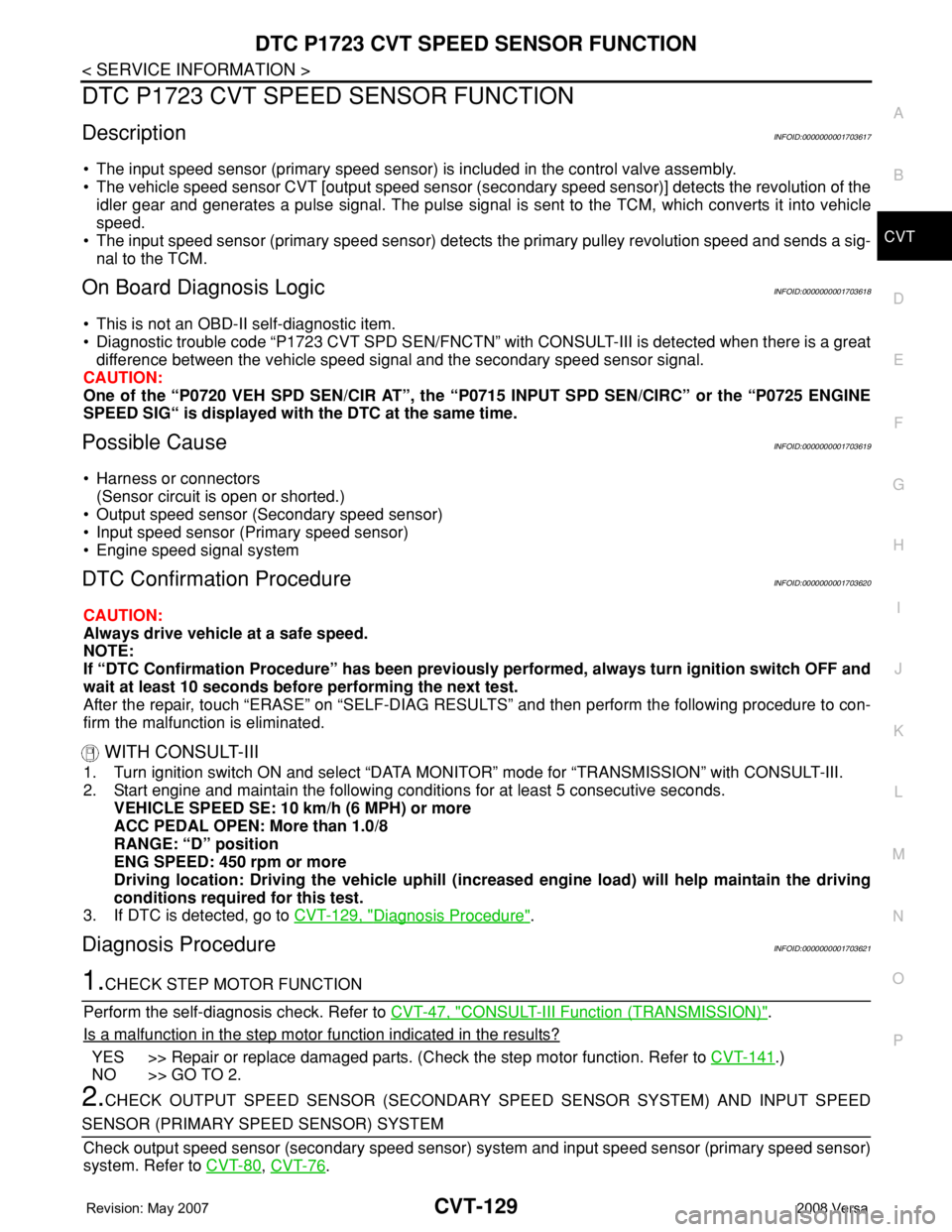
On Board Diagnosis LogicINFOID:0000000001703618
• This is not an OBD-II self-diagnostic item.
• Diagnostic trouble code “P1723 CVT SPD SEN/FNCTN” with CONSULT-III is detected when there is a great
difference between the vehicle speed signal and the secondary speed sensor signal.
CAUTION:
One of the “P0720 VEH SPD SEN/CIR AT”, the “P0715 INPUT SPD SEN/CIRC” or the “P0725 ENGINE
SPEED SIG“ is displayed with the DTC at the same time.
Possible CauseINFOID:0000000001703619
• Harness or connectors
(Sensor circuit is open or shorted.)
• Output speed sensor (Secondary speed sensor)
• Input speed sensor (Primary speed sensor)
• Engine speed signal system
DTC Confirmation ProcedureINFOID:0000000001703620
CAUTION:
Always drive vehicle at a safe speed.
NOTE:
If “DTC Confirmation Procedure” has been previously performed, always turn ignition switch OFF and
wait at least 10 seconds before performing the next test.
After the repair, touch “ERASE” on “SELF-DIAG RESULTS” and then perform the following procedure to con-
firm the malfunction is eliminated.
WITH CONSULT-III
1. Turn ignition switch ON and select “DATA MONITOR” mode for “TRANSMISSION” with CONSULT-III.
2. Start engine and maintain the following conditions for at least 5 consecutive seconds.
VEHICLE SPEED SE: 10 km/h (6 MPH) or more
ACC PEDAL OPEN: More than 1.0/8
RANGE: “D” position
ENG SPEED: 450 rpm or more
Driving location: Driving the vehicle uphill (increased engine load) will help maintain the driving
conditions required for this test.
3. If DTC is detected, go to CVT-129, "
Diagnosis Procedure".
Diagnosis ProcedureINFOID:0000000001703621
1.CHECK STEP MOTOR FUNCTION
Perform the self-diagnosis check. Refer to CVT-47, "
CONSULT-III Function (TRANSMISSION)".
Is a malfunction in the step motor function indicated in the results?
YES >> Repair or replace damaged parts. (Check the step motor function. Refer to CVT-141.)
NO >> GO TO 2.
2.CHECK OUTPUT SPEED SENSOR (SECONDARY SPEED SENSOR SYSTEM) AND INPUT SPEED
SENSOR (PRIMARY SPEED SENSOR) SYSTEM
Check output speed sensor (secondary speed sensor) system and input speed sensor (primary speed sensor)
system. Refer to CVT-80
, CVT-76.