2008 NISSAN LATIO ECU
[x] Cancel search: ECUPage 971 of 2771
CVT-132
< SERVICE INFORMATION >
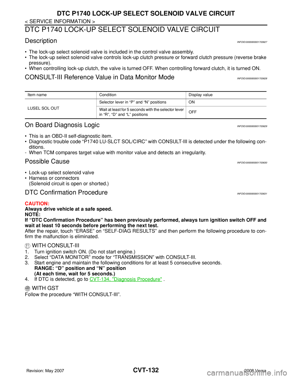
DTC P1740 LOCK-UP SELECT SOLENOID VALVE CIRCUIT
DTC P1740 LOCK-UP SELECT SOLENOID VALVE CIRCUIT
DescriptionINFOID:0000000001703627
• The lock-up select solenoid valve is included in the control valve assembly.
• The lock-up select solenoid valve controls lock-up clutch pressure or forward clutch pressure (reverse brake
pressure).
• When controlling lock-up clutch, the valve is turned OFF. When controlling forward clutch, it is turned ON.
CONSULT-III Reference Value in Data Monitor ModeINFOID:0000000001703628
On Board Diagnosis LogicINFOID:0000000001703629
• This is an OBD-II self-diagnostic item.
• Diagnostic trouble code “P1740 LU-SLCT SOL/CIRC” with CONSULT-III is detected under the following con-
ditions.
- When TCM compares target value with monitor value and detects an irregularity.
Possible CauseINFOID:0000000001703630
• Lock-up select solenoid valve
• Harness or connectors
(Solenoid circuit is open or shorted.)
DTC Confirmation ProcedureINFOID:0000000001703631
CAUTION:
Always drive vehicle at a safe speed.
NOTE:
If “DTC Confirmation Procedure” has been previously performed, always turn ignition switch OFF and
wait at least 10 seconds before performing the next test.
After the repair, touch “ERASE” on “SELF-DIAG RESULTS” and then perform the following procedure to con-
firm the malfunction is eliminated.
WITH CONSULT-III
1. Turn ignition switch ON. (Do not start engine.)
2. Select “DATA MONITOR” mode for “TRANSMISSION” with CONSULT-III.
3. Start engine and maintain the following conditions for at least 5 consecutive seconds.
RANGE: “D” position and “N” position
(At each time, wait for 5 seconds.)
4. If DTC is detected, go to CVT-134, "
Diagnosis Procedure" .
WITH GST
Follow the procedure “WITH CONSULT-III”.
Item name Condition Display value
LUSEL SOL OUTSelector lever in “P” and “N” positions ON
Wait at least for 5 seconds with the selector lever
in “R”, “D” and “L” positionsOFF
Page 976 of 2771
DTC P1777 STEP MOTOR - CIRCUIT
CVT-137
< SERVICE INFORMATION >
D
E
F
G
H
I
J
K
L
MA
B
CVT
N
O
P
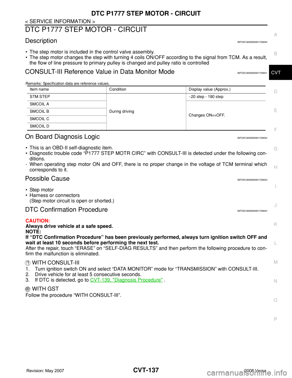
DTC P1777 STEP MOTOR - CIRCUIT
DescriptionINFOID:0000000001703640
• The step motor is included in the control valve assembly.
• The step motor changes the step with turning 4 coils ON/OFF according to the signal from TCM. As a result,
the flow of line pressure to primary pulley is changed and pulley ratio is controlled
CONSULT-III Reference Value in Data Monitor ModeINFOID:0000000001703641
Remarks: Specification data are reference values.
On Board Diagnosis LogicINFOID:0000000001703642
• This is an OBD-II self-diagnostic item.
• Diagnostic trouble code “P1777 STEP MOTR CIRC” with CONSULT-III is detected under the following con-
ditions.
- When operating step motor ON and OFF, there is no proper change in the voltage of TCM terminal which
corresponds to it.
Possible CauseINFOID:0000000001703643
• Step motor
• Harness or connectors
(Step motor circuit is open or shorted.)
DTC Confirmation ProcedureINFOID:0000000001703644
CAUTION:
Always drive vehicle at a safe speed.
NOTE:
If “DTC Confirmation Procedure” has been previously performed, always turn ignition switch OFF and
wait at least 10 seconds before performing the next test.
After the repair, touch “ERASE” on “SELF-DIAG RESULTS” and then perform the following procedure to con-
firm the malfunction is eliminated.
WITH CONSULT-III
1. Turn ignition switch ON and select “DATA MONITOR” mode for “TRANSMISSION” with CONSULT-III.
2. Drive vehicle for at least 5 consecutive seconds.
3. If DTC is detected, go to CVT-139, "
Diagnosis Procedure" .
WITH GST
Follow the procedure “WITH CONSULT-III”.
Item name Condition Display value (Approx.)
STM STEP
During driving−20 step - 180 step
SMCOIL A
Changes ON⇔OFF. SMCOIL B
SMCOIL C
SMCOIL D
Page 980 of 2771
DTC P1778 STEP MOTOR - FUNCTION
CVT-141
< SERVICE INFORMATION >
D
E
F
G
H
I
J
K
L
MA
B
CVT
N
O
P
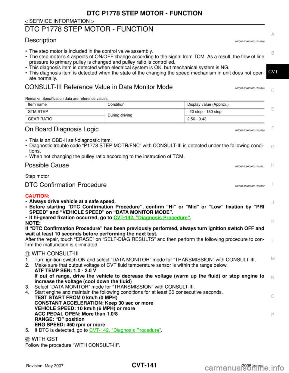
DTC P1778 STEP MOTOR - FUNCTION
DescriptionINFOID:0000000001703648
• The step motor is included in the control valve assembly.
• The step motor's 4 aspects of ON/OFF change according to the signal from TCM. As a result, the flow of line
pressure to primary pulley is changed and pulley ratio is controlled.
• This diagnosis item is detected when electrical system is OK, but mechanical system is NG.
• This diagnosis item is detected when the state of the changing the speed mechanism in unit does not oper-
ate normally.
CONSULT-III Reference Value in Data Monitor ModeINFOID:0000000001703649
Remarks: Specification data are reference values.
On Board Diagnosis LogicINFOID:0000000001703650
• This is an OBD-II self-diagnostic item.
• Diagnostic trouble code “P1778 STEP MOTR/FNC” with CONSULT-III is detected under the following condi-
tions.
- When not changing the pulley ratio according to the instruction of TCM.
Possible CauseINFOID:0000000001703651
Step motor
DTC Confirmation ProcedureINFOID:0000000001703652
CAUTION:
• Always drive vehicle at a safe speed.
• Before starting “DTC Confirmation Procedure”, confirm “Hi” or “Mid” or “Low” fixation by “PRI
SPEED” and “VEHICLE SPEED” on “DATA MONITOR MODE”.
• If hi-geared fixation occurred, go to CVT-142, "
Diagnosis Procedure".
NOTE:
If “DTC Confirmation Procedure” has been previously performed, always turn ignition switch OFF and
wait at least 10 seconds before performing the next test.
After the repair, touch “ERASE” on “SELF-DIAG RESULTS” and then perform the following procedure to con-
firm the malfunction is eliminated.
WITH CONSULT-III
1. Turn ignition switch ON and select “DATA MONITOR” mode for “TRANSMISSION” with CONSULT-III.
2. Make sure that output voltage of CVT fluid temperature sensor is within the range below.
ATF TEMP SEN: 1.0 - 2.0 V
If out of range, drive the vehicle to decrease the voltage (warm up the fluid) or stop engine to
increase the voltage (cool down the fluid)
3. Select “DATA MONITOR” mode for “TRANSMISSION” with CONSULT-III.
4. Start engine and maintain the following conditions for at least 30 consecutive seconds.
TEST START FROM 0 km/h (0 MPH)
CONSTANT ACCELERATION: Keep 30 sec or more
VEHICLE SPEED: 10 km/h (6 MPH) or more
ACC PEDAL OPEN: More than 1.0/8
RANGE: “D” position
ENG SPEED: 450 rpm or more
5. If DTC is detected, go to CVT-142, "
Diagnosis Procedure".
WITH GST
Follow the procedure “WITH CONSULT-III”.
Item name Condition Display value (Approx.)
STM STEP
During driving−20 step - 180 step
GEAR RATIO2.56 - 0.43
Page 984 of 2771
OVERDRIVE CONTROL SWITCH
CVT-145
< SERVICE INFORMATION >
D
E
F
G
H
I
J
K
L
MA
B
CVT
N
O
P
Perform the self-diagnosis check. Refer to CVT-47, "CONSULT-III Function (TRANSMISSION)".
Is any malfunction of the
“U1000 CAN COMM CIRCUIT” indicated in the results?
YES >> Check CAN communication line. Refer to CVT-56.
NO >> GO TO 2.
2.CHECK OVERDRIVE CONTROL SWITCH SIGNAL
With CONSULT-III
1. Turn ignition switch ON.
2. Select “ECU INPUT SIGNALS” in “DATA MONITOR” mode for “TRANSMISSION” with CONSULT-III.
3. Read out ON/OFF switching action of the “SPORT MODE SW”.
OK or NG
OK >>INSPECTION END
NG >> GO TO 3.
3.CHECK OVERDRIVE CONTROL SWITCH
Check overdrive control switch. Refer to CVT-146, "
Component Inspection"
OK or NG
OK >> GO TO 4.
NG >> Repair or replace damaged parts.
4.CHECK SELF-DIAGNOSTIC RESULTS (COMBINATION METER)
Perform self-diagnosis check. Refer to DI-11, "
Self-Diagnosis Mode of Combination Meter".
Is any malfunction detected by self-diagnostic?
YES >> Check the malfunctioning system.
NO - 1 >> With intelligent key: GO TO 5.
NO - 2 >> Without intelligent key: GO TO 6.
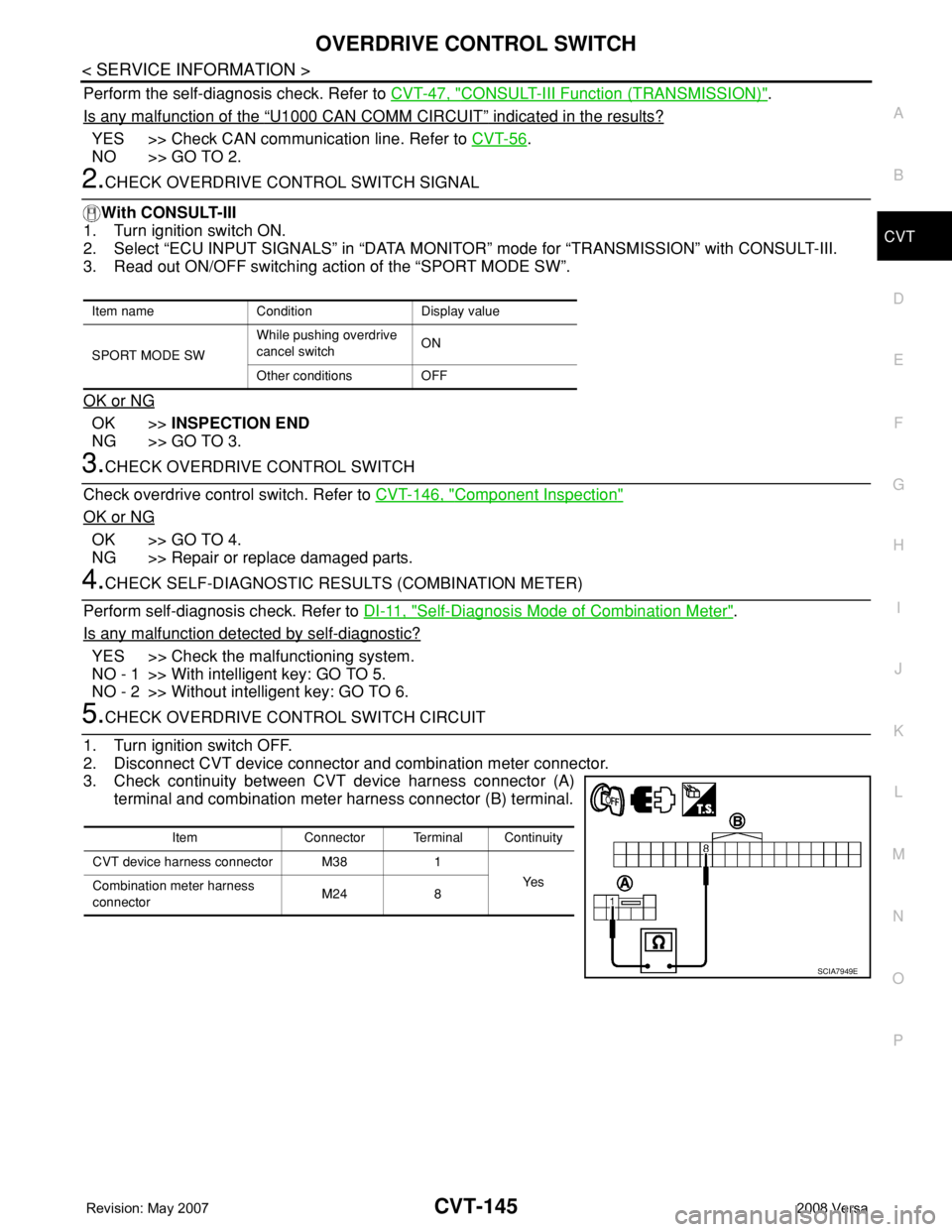
5.CHECK OVERDRIVE CONTROL SWITCH CIRCUIT
1. Turn ignition switch OFF.
2. Disconnect CVT device connector and combination meter connector.
3. Check continuity between CVT device harness connector (A)
terminal and combination meter harness connector (B) terminal.
Item name Condition Display value
SPORT MODE SWWhile pushing overdrive
cancel switchON
Other conditions OFF
Item Connector Terminal Continuity
CVT device harness connector M38 1
Ye s
Combination meter harness
connectorM24 8
SCIA7949E
Page 1010 of 2771
SHIFT CONTROL SYSTEM
CVT-171
< SERVICE INFORMATION >
D
E
F
G
H
I
J
K
L
MA
B
CVT
N
O
P
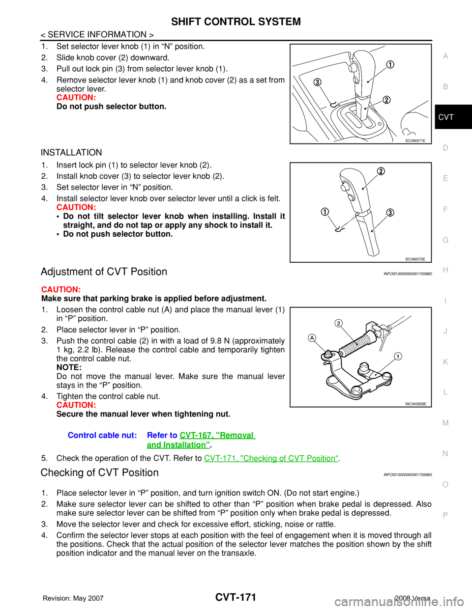
1. Set selector lever knob (1) in “N” position.
2. Slide knob cover (2) downward.
3. Pull out lock pin (3) from selector lever knob (1).
4. Remove selector lever knob (1) and knob cover (2) as a set from
selector lever.
CAUTION:
Do not push selector button.
INSTALLATION
1. Insert lock pin (1) to selector lever knob (2).
2. Install knob cover (3) to selector lever knob (2).
3. Set selector lever in “N” position.
4. Install selector lever knob over selector lever until a click is felt.
CAUTION:
• Do not tilt selector lever knob when installing. Install it
straight, and do not tap or apply any shock to install it.
• Do not push selector button.
Adjustment of CVT PositionINFOID:0000000001703682
CAUTION:
Make sure that parking brake is applied before adjustment.
1. Loosen the control cable nut (A) and place the manual lever (1)
in “P” position.
2. Place selector lever in “P” position.
3. Push the control cable (2) in with a load of 9.8 N (approximately
1 kg, 2.2 lb). Release the control cable and temporarily tighten
the control cable nut.
NOTE:
Do not move the manual lever. Make sure the manual lever
stays in the “P” position.
4. Tighten the control cable nut.
CAUTION:
Secure the manual lever when tightening nut.
5. Check the operation of the CVT. Refer to CVT-171, "
Checking of CVT Position".
Checking of CVT PositionINFOID:0000000001703683
1. Place selector lever in “P” position, and turn ignition switch ON. (Do not start engine.)
2. Make sure selector lever can be shifted to other than “P” position when brake pedal is depressed. Also
make sure selector lever can be shifted from “P” position only when brake pedal is depressed.
3. Move the selector lever and check for excessive effort, sticking, noise or rattle.
4. Confirm the selector lever stops at each position with the feel of engagement when it is moved through all
the positions. Check that the actual position of the selector lever matches the position shown by the shift
position indicator and the manual lever on the transaxle.
SCIA6971E
SCIA6972E
Control cable nut: Refer to CVT-167, "Removal
and Installation".
WCIA0608E
Page 1013 of 2771
CVT-174
< SERVICE INFORMATION >
KEY INTERLOCK CABLE
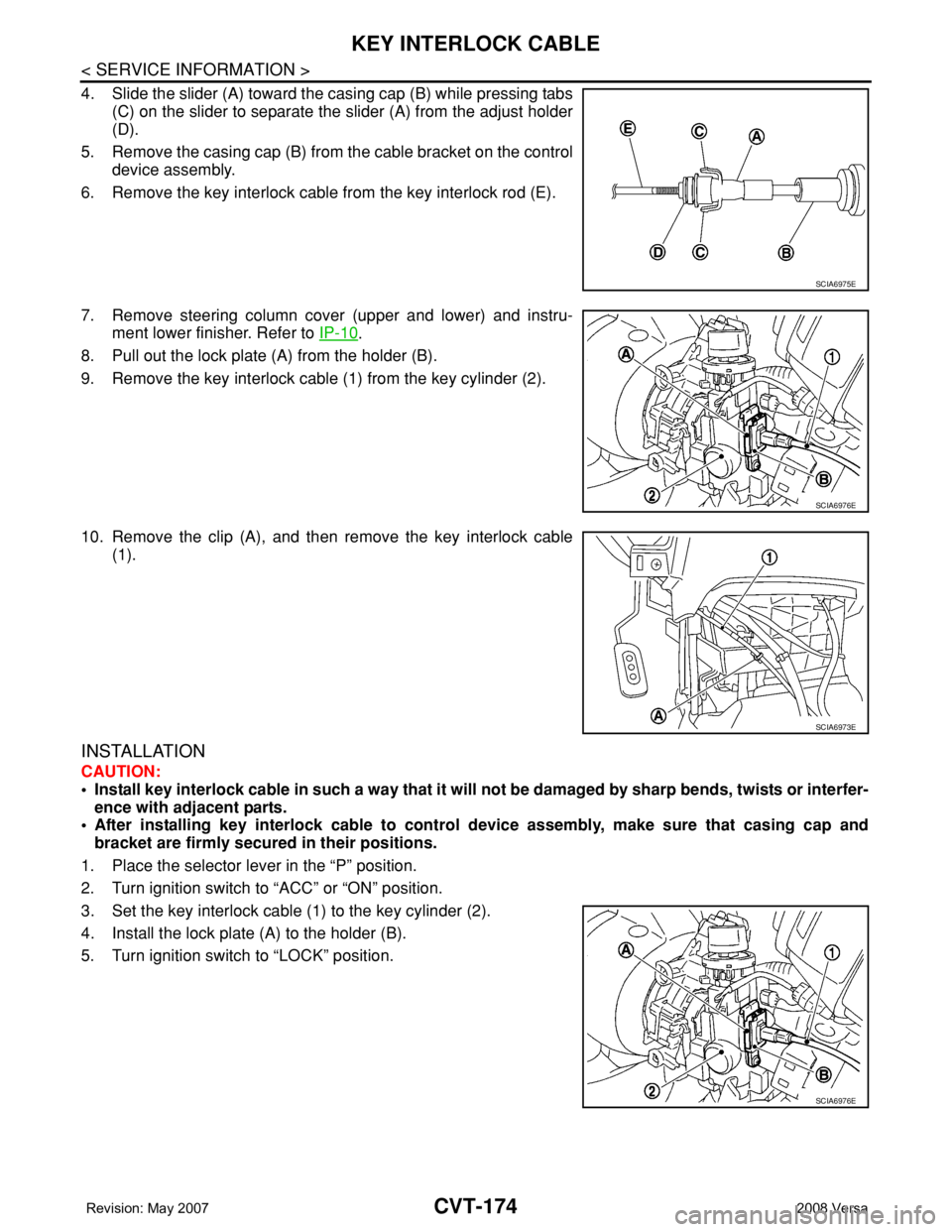
4. Slide the slider (A) toward the casing cap (B) while pressing tabs
(C) on the slider to separate the slider (A) from the adjust holder
(D).
5. Remove the casing cap (B) from the cable bracket on the control
device assembly.
6. Remove the key interlock cable from the key interlock rod (E).
7. Remove steering column cover (upper and lower) and instru-
ment lower finisher. Refer to IP-10
.
8. Pull out the lock plate (A) from the holder (B).
9. Remove the key interlock cable (1) from the key cylinder (2).
10. Remove the clip (A), and then remove the key interlock cable
(1).
INSTALLATION
CAUTION:
• Install key interlock cable in such a way that it will not be damaged by sharp bends, twists or interfer-
ence with adjacent parts.
• After installing key interlock cable to control device assembly, make sure that casing cap and
bracket are firmly secured in their positions.
1. Place the selector lever in the “P” position.
2. Turn ignition switch to “ACC” or “ON” position.
3. Set the key interlock cable (1) to the key cylinder (2).
4. Install the lock plate (A) to the holder (B).
5. Turn ignition switch to “LOCK” position.
SCIA6975E
SCIA6976E
SCIA6973E
SCIA6976E
Page 1014 of 2771
KEY INTERLOCK CABLE
CVT-175
< SERVICE INFORMATION >
D
E
F
G
H
I
J
K
L
MA
B
CVT
N
O
P
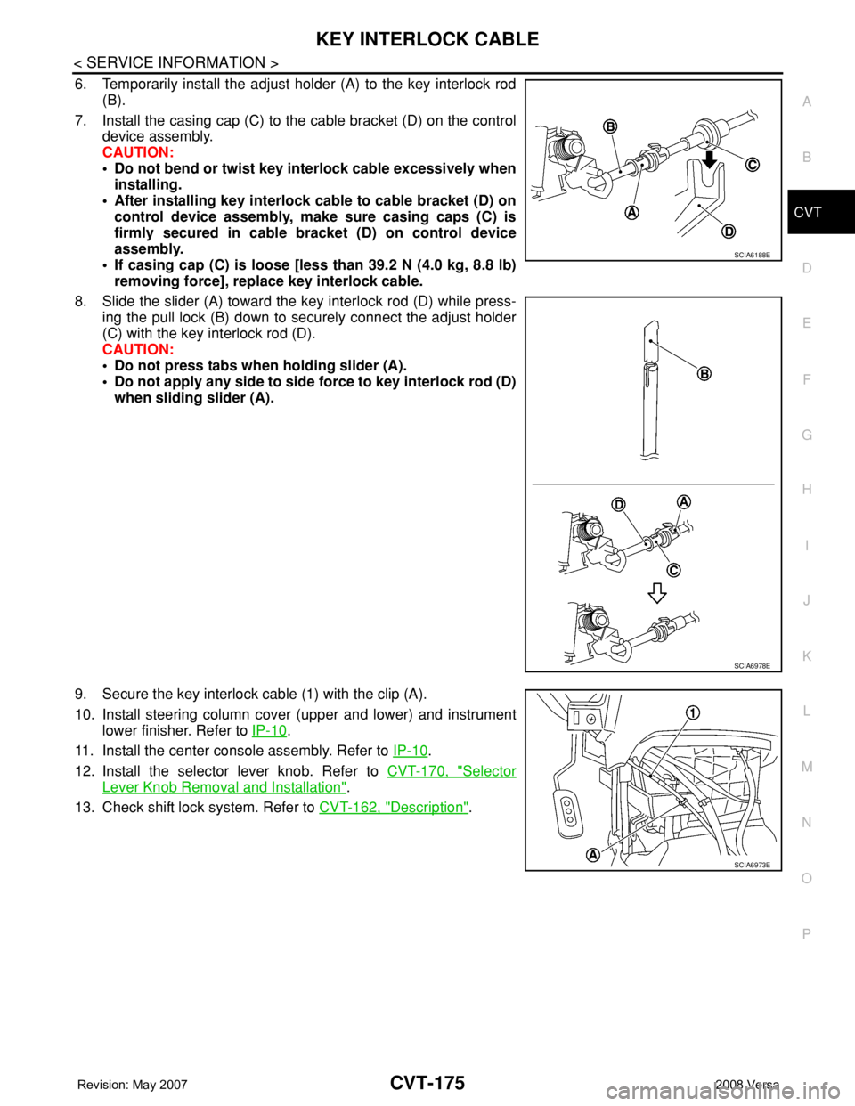
6. Temporarily install the adjust holder (A) to the key interlock rod
(B).
7. Install the casing cap (C) to the cable bracket (D) on the control
device assembly.
CAUTION:
• Do not bend or twist key interlock cable excessively when
installing.
• After installing key interlock cable to cable bracket (D) on
control device assembly, make sure casing caps (C) is
firmly secured in cable bracket (D) on control device
assembly.
• If casing cap (C) is loose [less than 39.2 N (4.0 kg, 8.8 lb)
removing force], replace key interlock cable.
8. Slide the slider (A) toward the key interlock rod (D) while press-
ing the pull lock (B) down to securely connect the adjust holder
(C) with the key interlock rod (D).
CAUTION:
• Do not press tabs when holding slider (A).
• Do not apply any side to side force to key interlock rod (D)
when sliding slider (A).
9. Secure the key interlock cable (1) with the clip (A).
10. Install steering column cover (upper and lower) and instrument
lower finisher. Refer to IP-10
.
11. Install the center console assembly. Refer to IP-10
.
12. Install the selector lever knob. Refer to CVT-170, "
Selector
Lever Knob Removal and Installation".
13. Check shift lock system. Refer to CVT-162, "
Description".
SCIA6188E
SCIA6978E
SCIA6973E
Page 1018 of 2771
TRANSAXLE ASSEMBLY
CVT-179
< SERVICE INFORMATION >
D
E
F
G
H
I
J
K
L
MA
B
CVT
N
O
P
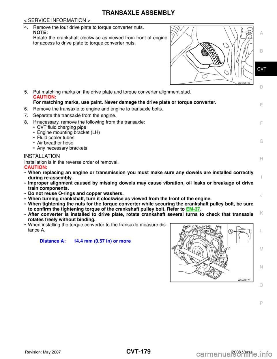
4. Remove the four drive plate to torque converter nuts.
NOTE:
Rotate the crankshaft clockwise as viewed from front of engine
for access to drive plate to torque converter nuts.
5. Put matching marks on the drive plate and torque converter alignment stud.
CAUTION:
For matching marks, use paint. Never damage the drive plate or torque converter.
6. Remove the transaxle to engine and engine to transaxle bolts.
7. Separate the transaxle from the engine.
8. If necessary, remove the following from the transaxle:
• CVT fluid charging pipe
• Engine mounting bracket (LH)
• Fluid cooler tubes
• Air breather hose
• Any necessary brackets
INSTALLATION
Installation is in the reverse order of removal.
CAUTION:
• When replacing an engine or transmission you must make sure any dowels are installed correctly
during re-assembly.
• Improper alignment caused by missing dowels may cause vibration, oil leaks or breakage of drive
train components.
• Do not reuse O-rings and copper washers.
• When turning crankshaft, turn it clockwise as viewed from the front of the engine.
• When tightening the nuts for the torque converter while securing the crankshaft pulley bolt, be sure
to confirm the tightening torque of the crankshaft pulley bolt. Refer to EM-37
.
• After converter is installed to drive plate, rotate crankshaft several turns to check that transaxle
rotates freely without binding.
• When installing the torque converter to the transaxle measure dis-
tance A.
WCIA0616E
Distance A: 14.4 mm (0.57 in) or more
WCIA0617E