Page 569 of 2771
INTELLIGENT KEY SYSTEM
BL-135
< SERVICE INFORMATION >
C
D
E
F
G
H
J
K
L
MA
B
BL
N
O
P
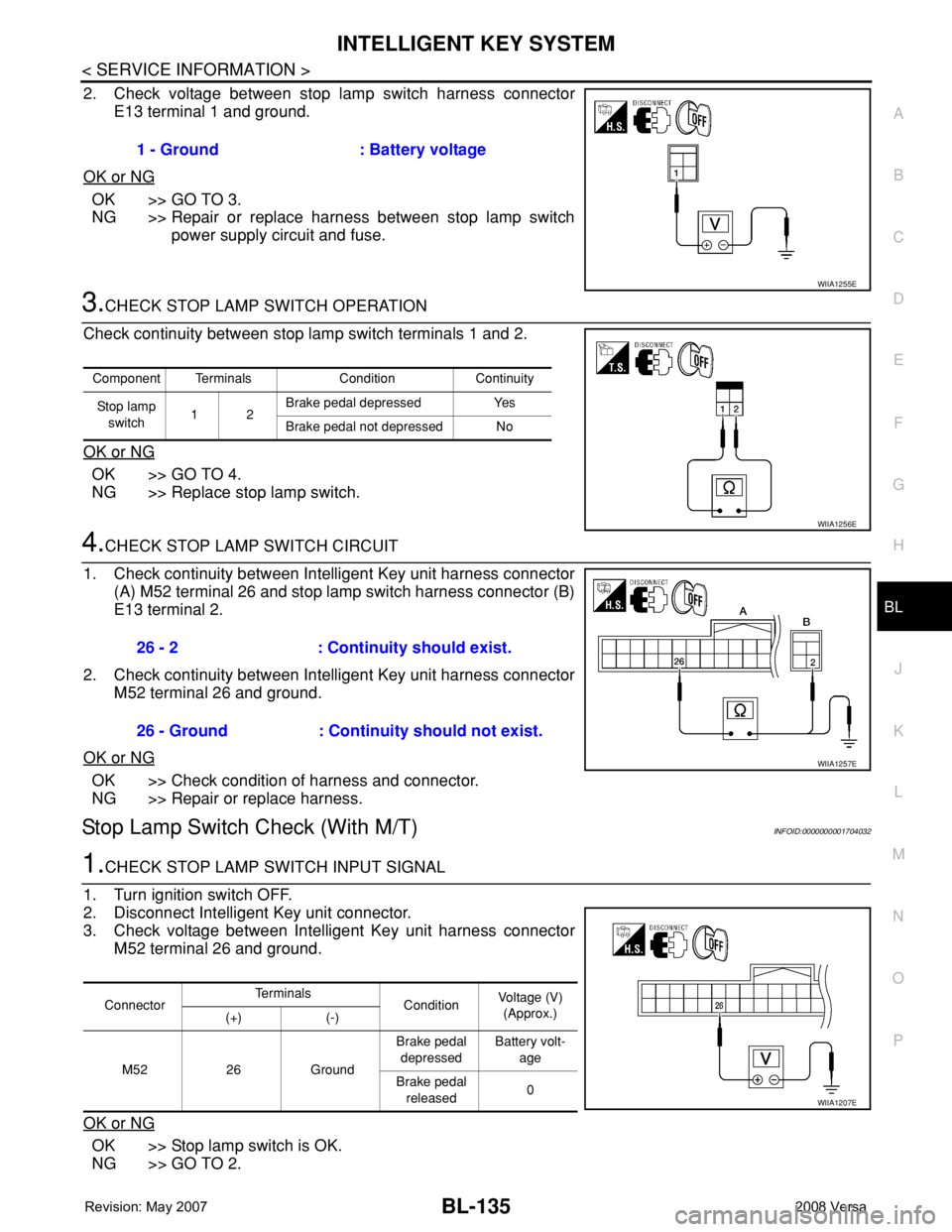
2. Check voltage between stop lamp switch harness connector
E13 terminal 1 and ground.
OK or NG
OK >> GO TO 3.
NG >> Repair or replace harness between stop lamp switch
power supply circuit and fuse.
3.CHECK STOP LAMP SWITCH OPERATION
Check continuity between stop lamp switch terminals 1 and 2.
OK or NG
OK >> GO TO 4.
NG >> Replace stop lamp switch.
4.CHECK STOP LAMP SWITCH CIRCUIT
1. Check continuity between Intelligent Key unit harness connector
(A) M52 terminal 26 and stop lamp switch harness connector (B)
E13 terminal 2.
2. Check continuity between Intelligent Key unit harness connector
M52 terminal 26 and ground.
OK or NG
OK >> Check condition of harness and connector.
NG >> Repair or replace harness.
Stop Lamp Switch Check (With M/T)INFOID:0000000001704032
1.CHECK STOP LAMP SWITCH INPUT SIGNAL
1. Turn ignition switch OFF.
2. Disconnect Intelligent Key unit connector.
3. Check voltage between Intelligent Key unit harness connector
M52 terminal 26 and ground.
OK or NG
OK >> Stop lamp switch is OK.
NG >> GO TO 2.1 - Ground : Battery voltage
WIIA1255E
Component Terminals Condition Continuity
Stop lamp
switch12Brake pedal depressed Yes
Brake pedal not depressed No
WIIA1256E
26 - 2 : Continuity should exist.
26 - Ground : Continuity should not exist.
WIIA1257E
ConnectorTe r m i n a l s
ConditionVoltage (V)
(Approx.)
(+) (-)
M52 26 GroundBrake pedal
depressedBattery volt-
age
Brake pedal
released0
WIIA1207E
Page 570 of 2771
BL-136
< SERVICE INFORMATION >
INTELLIGENT KEY SYSTEM
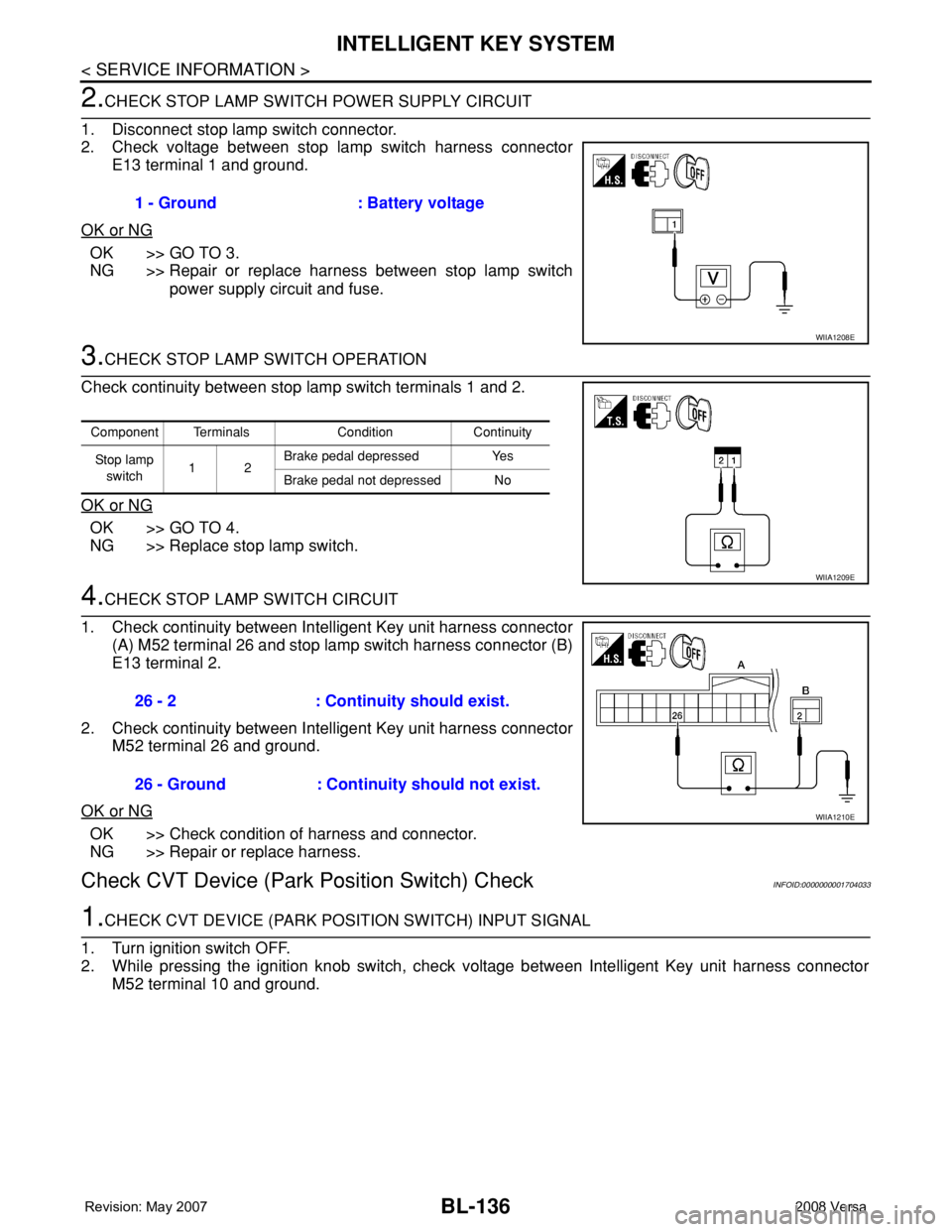
2.CHECK STOP LAMP SWITCH POWER SUPPLY CIRCUIT
1. Disconnect stop lamp switch connector.
2. Check voltage between stop lamp switch harness connector
E13 terminal 1 and ground.
OK or NG
OK >> GO TO 3.
NG >> Repair or replace harness between stop lamp switch
power supply circuit and fuse.
3.CHECK STOP LAMP SWITCH OPERATION
Check continuity between stop lamp switch terminals 1 and 2.
OK or NG
OK >> GO TO 4.
NG >> Replace stop lamp switch.
4.CHECK STOP LAMP SWITCH CIRCUIT
1. Check continuity between Intelligent Key unit harness connector
(A) M52 terminal 26 and stop lamp switch harness connector (B)
E13 terminal 2.
2. Check continuity between Intelligent Key unit harness connector
M52 terminal 26 and ground.
OK or NG
OK >> Check condition of harness and connector.
NG >> Repair or replace harness.
Check CVT Device (Park Position Switch) CheckINFOID:0000000001704033
1.CHECK CVT DEVICE (PARK POSITION SWITCH) INPUT SIGNAL
1. Turn ignition switch OFF.
2. While pressing the ignition knob switch, check voltage between Intelligent Key unit harness connector
M52 terminal 10 and ground.1 - Ground : Battery voltage
WIIA1208E
Component Terminals Condition Continuity
St op la mp
switch12Brake pedal depressed Yes
Brake pedal not depressed No
WIIA1209E
26 - 2 : Continuity should exist.
26 - Ground : Continuity should not exist.
WIIA1210E
Page 571 of 2771
INTELLIGENT KEY SYSTEM
BL-137
< SERVICE INFORMATION >
C
D
E
F
G
H
J
K
L
MA
B
BL
N
O
P
OK or NG
OK >> Replace Intelligent Key unit. Refer to BL-142, "Removal
and Installation of Intelligent Key Unit".
NG >> GO TO 2.
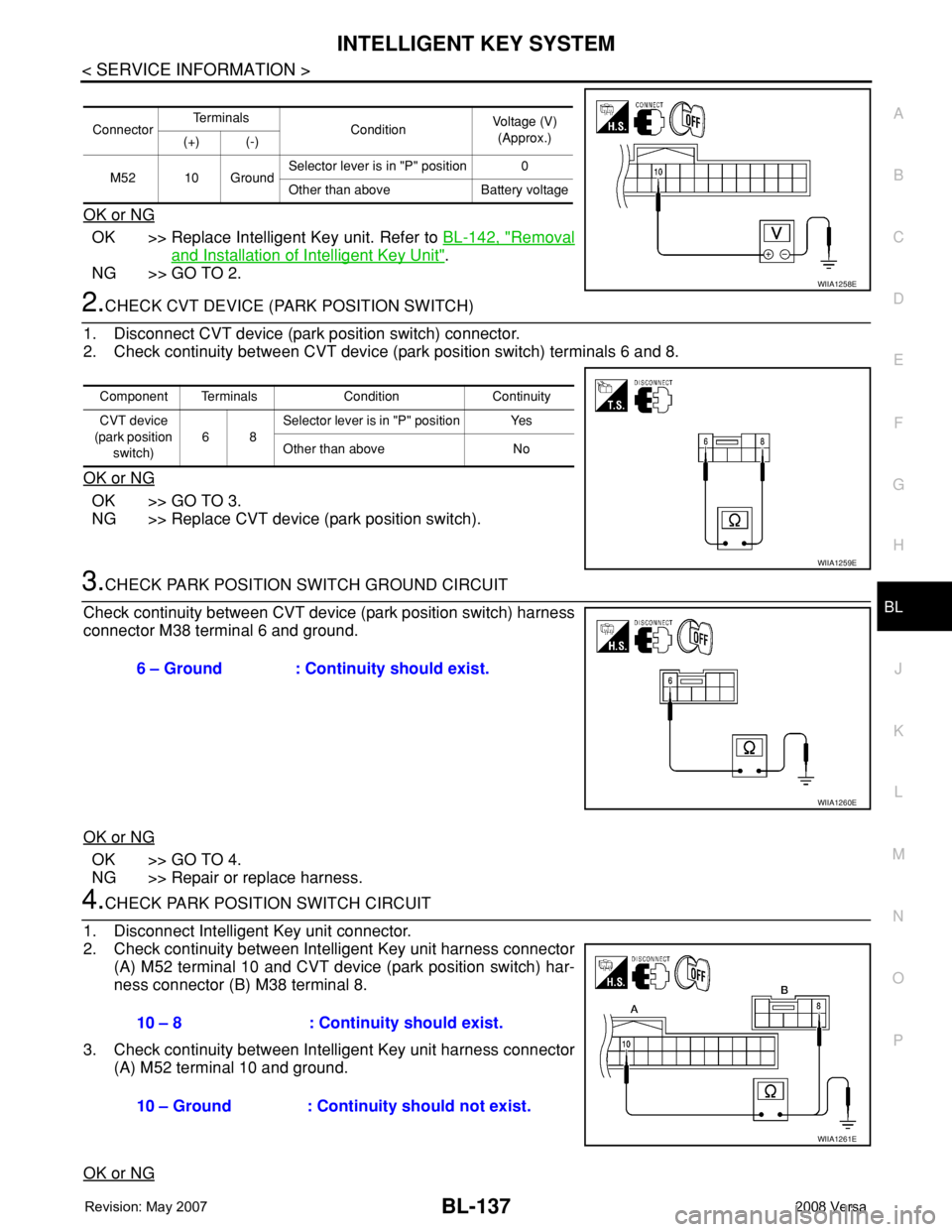
2.CHECK CVT DEVICE (PARK POSITION SWITCH)
1. Disconnect CVT device (park position switch) connector.
2. Check continuity between CVT device (park position switch) terminals 6 and 8.
OK or NG
OK >> GO TO 3.
NG >> Replace CVT device (park position switch).
3.CHECK PARK POSITION SWITCH GROUND CIRCUIT
Check continuity between CVT device (park position switch) harness
connector M38 terminal 6 and ground.
OK or NG
OK >> GO TO 4.
NG >> Repair or replace harness.
4.CHECK PARK POSITION SWITCH CIRCUIT
1. Disconnect Intelligent Key unit connector.
2. Check continuity between Intelligent Key unit harness connector
(A) M52 terminal 10 and CVT device (park position switch) har-
ness connector (B) M38 terminal 8.
3. Check continuity between Intelligent Key unit harness connector
(A) M52 terminal 10 and ground.
OK or NG
ConnectorTe r m i n a l s
ConditionVoltage (V)
(Approx.)
(+) (-)
M52 10 GroundSelector lever is in "P" position 0
Other than above Battery voltage
WIIA1258E
Component Terminals Condition Continuity
CVT device
(park position
switch)68Selector lever is in "P" position Yes
Other than above No
WIIA1259E
6 – Ground : Continuity should exist.
WIIA1260E
10 – 8 : Continuity should exist.
10 – Ground : Continuity should not exist.
WIIA1261E
Page 572 of 2771
BL-138
< SERVICE INFORMATION >
INTELLIGENT KEY SYSTEM
OK >> GO TO 5.
NG >> Repair or replace harness.
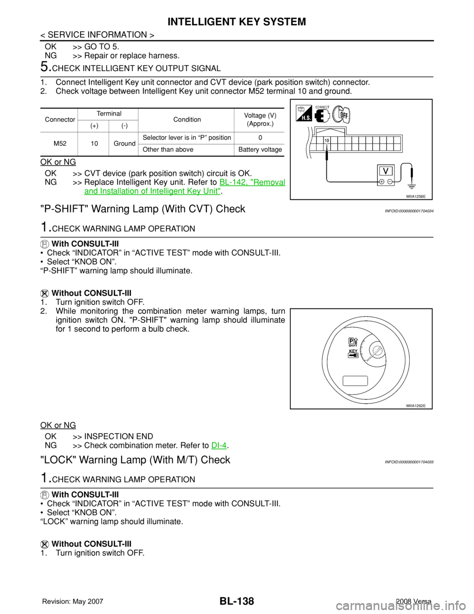
5.CHECK INTELLIGENT KEY OUTPUT SIGNAL
1. Connect Intelligent Key unit connector and CVT device (park position switch) connector.
2. Check voltage between Intelligent Key unit connector M52 terminal 10 and ground.
OK or NG
OK >> CVT device (park position switch) circuit is OK.
NG >> Replace Intelligent Key unit. Refer to BL-142, "
Removal
and Installation of Intelligent Key Unit".
"P-SHIFT" Warning Lamp (With CVT) CheckINFOID:0000000001704034
1.CHECK WARNING LAMP OPERATION
With CONSULT-III
• Check “INDICATOR” in “ACTIVE TEST” mode with CONSULT-III.
• Select “KNOB ON”.
“P-SHIFT” warning lamp should illuminate.
Without CONSULT-III
1. Turn ignition switch OFF.
2. While monitoring the combination meter warning lamps, turn
ignition switch ON. "P-SHIFT" warning lamp should illuminate
for 1 second to perform a bulb check.
OK or NG
OK >> INSPECTION END
NG >> Check combination meter. Refer to DI-4
.
"LOCK" Warning Lamp (With M/T) CheckINFOID:0000000001704035
1.CHECK WARNING LAMP OPERATION
With CONSULT-III
• Check “INDICATOR” in “ACTIVE TEST” mode with CONSULT-III.
• Select “KNOB ON”.
“LOCK” warning lamp should illuminate.
Without CONSULT-III
1. Turn ignition switch OFF.
ConnectorTe r m i n a l
ConditionVoltage (V)
(Approx.)
(+) (-)
M52 10 GroundSelector lever is in “P” position 0
Other than above Battery voltage
WIIA1258E
WIIA1262E
Page 575 of 2771
INTELLIGENT KEY SYSTEM
BL-141
< SERVICE INFORMATION >
C
D
E
F
G
H
J
K
L
MA
B
BL
N
O
P
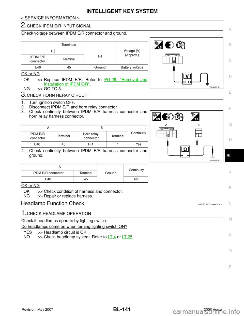
2.CHECK IPDM E/R INPUT SIGNAL
Check voltage between IPDM E/R connector and ground.
OK or NG
OK >> Replace IPDM E/R. Refer to PG-26, "Removal and
Installation of IPDM E/R".
NG >> GO TO 3.
3.CHECK HORN RERAY CIRCUIT
1. Turn ignition switch OFF.
2. Disconnect IPDM E/R and horn relay connector.
3. Check continuity between IPDM E/R harness connector and
horn relay harness connector.
4. Check continuity between IPDM E/R harness connector and
ground.
OK or NG
OK >> Check condition of harness and connector.
NG >> Repair or replace harness.
Headlamp Function CheckINFOID:0000000001704041
1.CHECK HEADLAMP OPERATION
Check if headlamps operate by lighting switch.
Do headlamps come on when turning lighting switch ON?
YES >> Headlamp circuit is OK.
NO >> Check headlamp system. Refer to LT- 4
or LT- 2 5.
Te r m i n a l s
Voltage (V)
(Approx.) (+)
(–)
IPDM E/R
connectorTe r m i n a l
E46 45 Ground Battery voltage
WIIA1251E
AB
Continuity
IPDM E/R
connectorTe r m i n a lHorn relay
connectorTe r m i n a l
E46 45 H-1 1 Yes
A
GroundContinuity
IPDM E/R connector Terminal
E46 45 No
WIIA1252E
Page 576 of 2771
BL-142
< SERVICE INFORMATION >
INTELLIGENT KEY SYSTEM
Intelligent Key Battery Replacement
INFOID:0000000001704042
INTELLIGENT KEY BATTERY INSPECTION
Check by connecting a resistance (approximately 300Ω) so that the
current value becomes about 10 mA.
Remote Keyless Entry FunctionINFOID:0000000001704043
Check keyfob function using Remote Keyless Entry Tester J-43241.
Removal and Installation of Intelligent Key UnitINFOID:0000000001704044
REMOVAL
1. Remove glove box assembly. Refer to IP-11, "Removal and Installation".
PIIB5065E
Standard : Approx. 2.5 - 3.0V
OCC0607D
LEL946A
Page 594 of 2771
BL-160
< SERVICE INFORMATION >
BACK DOOR LOCK
BCM Power Supply and Ground Circuit
INFOID:0000000001704059
Refer to BCS-15, "BCM Power Supply and Ground Circuit Inspection".
Check Back Door Opener Switch Circuit (Without Intelligent Key or Power Windows)
INFOID:0000000001704060
1.CHECK BACK DOOR OPENER SWITCH SIGNAL 1
With CONSULT-III
1. Insure front door lock knob LH is turned to the UNLOCK position.
2. Check back door opener switch (“TRNK OPNR SW”) in “DATA MONITOR” mode with CONSULT-III.
Without CONSULT-III
1. Insure front door lock knob LH is turned to the UNLOCK position.
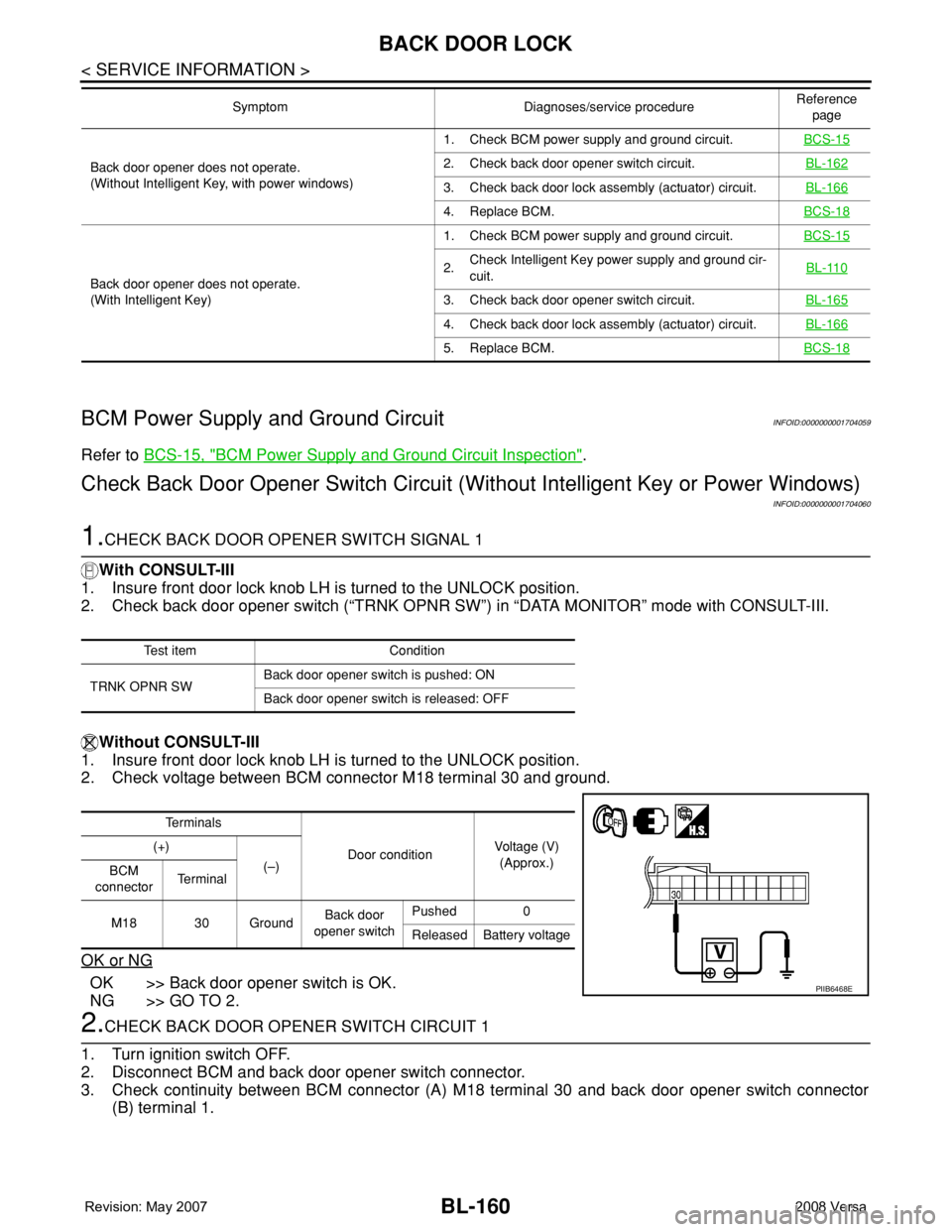
2. Check voltage between BCM connector M18 terminal 30 and ground.
OK or NG
OK >> Back door opener switch is OK.
NG >> GO TO 2.
2.CHECK BACK DOOR OPENER SWITCH CIRCUIT 1
1. Turn ignition switch OFF.
2. Disconnect BCM and back door opener switch connector.
3. Check continuity between BCM connector (A) M18 terminal 30 and back door opener switch connector
(B) terminal 1.
Back door opener does not operate.
(Without Intelligent Key, with power windows)1. Check BCM power supply and ground circuit.BCS-152. Check back door opener switch circuit.BL-162
3. Check back door lock assembly (actuator) circuit.BL-166
4. Replace BCM.BCS-18
Back door opener does not operate.
(With Intelligent Key)1. Check BCM power supply and ground circuit.BCS-15
2.Check Intelligent Key power supply and ground cir-
cuit.BL-110
3. Check back door opener switch circuit.BL-165
4. Check back door lock assembly (actuator) circuit.BL-166
5. Replace BCM.BCS-18
Symptom Diagnoses/service procedureReference
page
Test item Condition
TRNK OPNR SWBack door opener switch is pushed: ON
Back door opener switch is released: OFF
Te r m i n a l s
Door conditionVoltage (V)
(Approx.) (+)
(–)
BCM
connectorTe r m i n a l
M18 30 GroundBack door
opener switchPushed 0
Released Battery voltage
PIIB6468E
Page 596 of 2771
BL-162
< SERVICE INFORMATION >
BACK DOOR LOCK
OK or NG
OK >> GO TO 6.
NG >> Repair or replace harness.
6.CHECK UNLOCK SENSOR FUNCTION
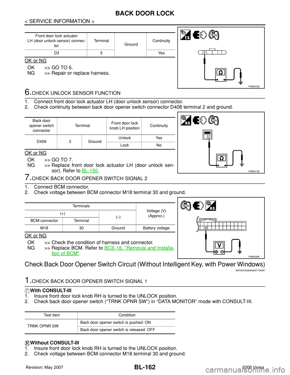
1. Connect front door lock actuator LH (door unlock sensor) connector.
2. Check continuity between back door opener switch connector D408 terminal 2 and ground.
OK or NG
OK >> GO TO 7.
NG >> Replace front door lock actuator LH (door unlock sen-
sor). Refer to BL-150
.
7.CHECK BACK DOOR OPENER SWITCH SIGNAL 2
1. Connect BCM connector.
2. Check voltage between BCM connector M18 terminal 30 and ground.
OK or NG
OK >> Check the condition of harness and connector.
NG >> Replace BCM. Refer to BCS-18, "
Removal and Installa-
tion of BCM".
Check Back Door Opener Switch Circuit (Without Intelligent Key, with Power Windows)
INFOID:0000000001704061
1.CHECK BACK DOOR OPENER SWITCH SIGNAL 1
With CONSULT-III
1. Insure front door lock knob RH is turned to the UNLOCK position.
2. Check back door opener switch (“TRNK OPNR SW”) in “DATA MONITOR” mode with CONSULT-III.
Without CONSULT-III
1. Insure front door lock knob RH is turned to the UNLOCK position.
2. Check voltage between BCM connector M18 terminal 30 and ground.
Front door lock actuator
LH (door unlock sensor) connec-
torTe r m i n a l
GroundContinuity
D3 5 Yes
PIIB6423E
Back door
opener switch
connectorTe r m i n a lFront door lock
knob LH positionContinuity
D408 2 GroundUnlock Yes
Lock No
PIIB6472E
Te r m i n a l s
Voltage (V)
(Approx.) (+)
(–)
BCM connector Terminal
M18 30 Ground Battery voltage
PIIB6468E
Test item Condition
TRNK OPNR SWBack door opener switch is pushed: ON
Back door opener switch is released: OFF