2008 NISSAN LATIO display
[x] Cancel search: displayPage 206 of 2771
AT-194
< SERVICE INFORMATION >
TROUBLE DIAGNOSIS FOR SYMPTOMS
OK or NG
OK >> Go to AT-186, "A/T Does Not Shift: D2→ D3" .
NG >> Check overdrive control switch. Refer to AT-171, "
Component Inspection" .
A/T Does Not Shift: D3→ 22, When Selector Lever "D" → "2" PositionINFOID:0000000001703351
SYMPTOM:
A/T does not shift from D3 to 22 when changing selector lever from “D” to “2” position on “Cruise
Test — Part 3”.
DIAGNOSTIC PROCEDURE
1.CHECK SYMPTOM
Check symptom. Refer to AT-55, "
Cruise Test - Part 1" or AT-58, "Cruise Test - Part 2" .
Is
“A/T Does Not Shift: D1 → D2 or Does Not Kickdown: D4→ D2” OK?
YES (With CONSULT-III) >>GO TO 2.
YES (Without CONSULT-III) >>GO TO 3.
NO >> Go to AT-185, "
A/T Does Not Shift: D1→ D2or Does Not Kickdown: D4→ D2" .
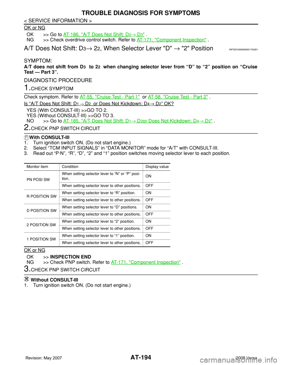
2.CHECK PNP SWITCH CIRCUIT
With CONSULT-III
1. Turn ignition switch ON. (Do not start engine.)
2. Select “TCM INPUT SIGNALS” in “DATA MONITOR” mode for “A/T” with CONSULT-III.
3. Read out “P·N”, “R”, “D”, “2” and “1” position switches moving selector lever to each position.
OK or NG
OK >>INSPECTION END
NG >> Check PNP switch. Refer to AT-171, "
Component Inspection" .
3.CHECK PNP SWITCH CIRCUIT
Without CONSULT-III
1. Turn ignition switch ON. (Do not start engine.)
Monitor item Condition Display value
PN POSI SWWhen setting selector lever to “N” or “P” posi-
tion.ON
When setting selector lever to other positions. OFF
R POSITION SWWhen setting selector lever to “R” position. ON
When setting selector lever to other positions. OFF
D POSITION SWWhen setting selector lever to “D” positions. ON
When setting selector lever to other positions. OFF
2 POSITION SWWhen setting selector lever to “2” position. ON
When setting selector lever to other positions. OFF
1 POSITION SWWhen setting selector lever to “1” position. ON
When setting selector lever to other positions. OFF
Page 207 of 2771
TROUBLE DIAGNOSIS FOR SYMPTOMS
AT-195
< SERVICE INFORMATION >
D
E
F
G
H
I
J
K
L
MA
B
AT
N
O
P
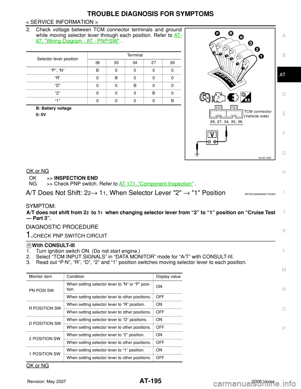
2. Check voltage between TCM connector terminals and ground
while moving selector lever through each position. Refer to AT-
87, "Wiring Diagram - AT - PNP/SW" .
B: Battery voltage
0: 0V
OK or NG
OK >>INSPECTION END
NG >> Check PNP switch. Refer to AT-171, "
Component Inspection" .
A/T Does Not Shift: 22→ 11, When Selector Lever "2" → "1" PositionINFOID:0000000001703352
SYMPTOM:
A/T does not shift from 22 to 11 when changing selector lever from “2” to “1” position on “Cruise Test
— Part 3”.
DIAGNOSTIC PROCEDURE
1.CHECK PNP SWITCH CIRCUIT
With CONSULT-III
1. Turn ignition switch ON. (Do not start engine.)
2. Select “TCM INPUT SIGNALS” in “DATA MONITOR” mode for “A/T” with CONSULT-III.
3. Read out “P·N”, “R”, “D”, “2” and “1” position switches moving selector lever to each position.
OK or NG
Selector lever positionTe r m i n a l
36 35 34 27 26
“P”, “N” B 0 0 0 0
“R” 0B000
“D” 0 0 B 0 0
“2” 0 0 0 B 0
“1” 0 0 0 0 B
SCIA7162E
Monitor item Condition Display value
PN POSI SWWhen setting selector lever to “N” or “P” posi-
tion.ON
When setting selector lever to other positions. OFF
R POSITION SWWhen setting selector lever to “R” position. ON
When setting selector lever to other positions. OFF
D POSITION SWWhen setting selector lever to “D” positions. ON
When setting selector lever to other positions. OFF
2 POSITION SWWhen setting selector lever to “2” position. ON
When setting selector lever to other positions. OFF
1 POSITION SWWhen setting selector lever to “1” position. ON
When setting selector lever to other positions. OFF
Page 210 of 2771
AT-198
< SERVICE INFORMATION >
TROUBLE DIAGNOSIS FOR SYMPTOMS
Without CONSULT-III
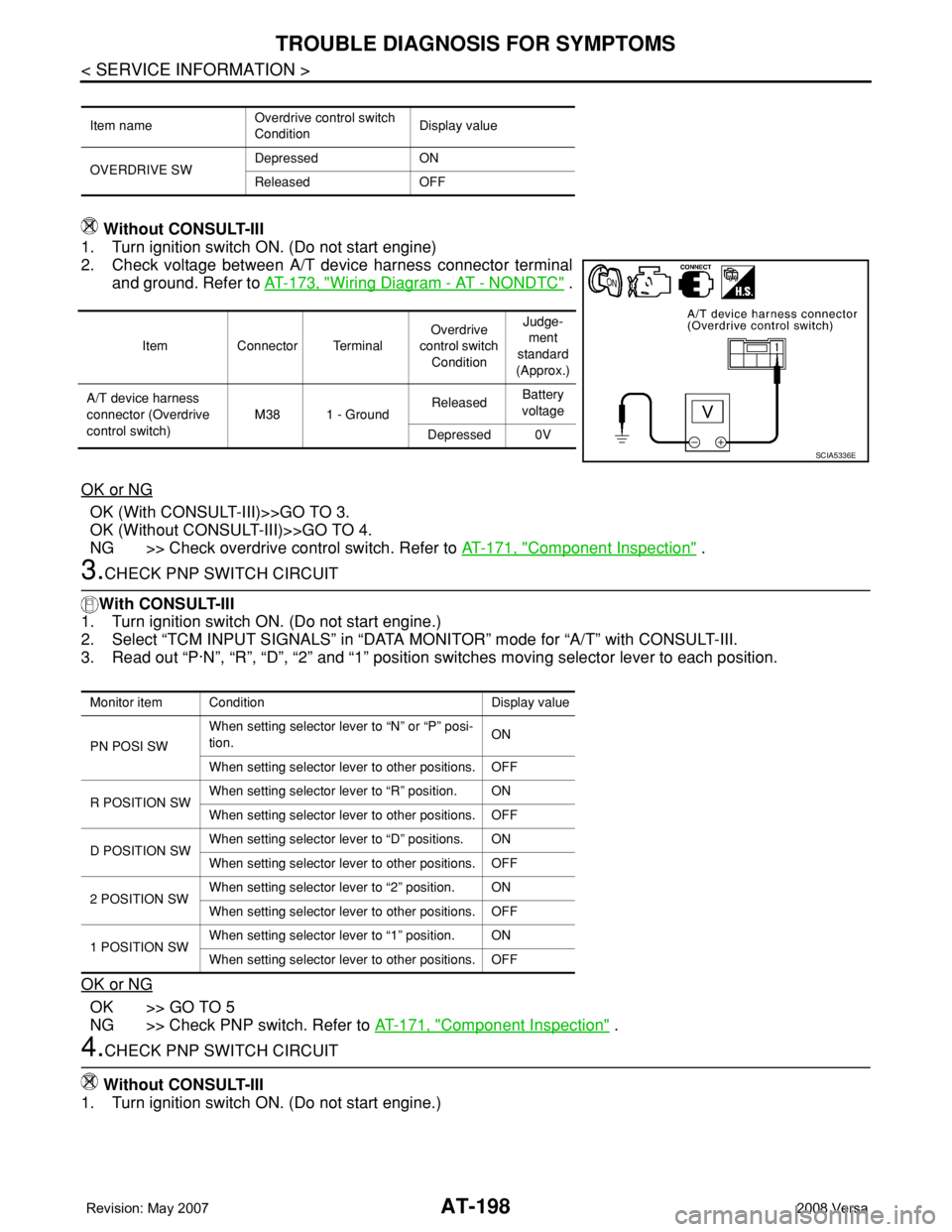
1. Turn ignition switch ON. (Do not start engine)
2. Check voltage between A/T device harness connector terminal
and ground. Refer to AT-173, "
Wiring Diagram - AT - NONDTC" .
OK or NG
OK (With CONSULT-III)>>GO TO 3.
OK (Without CONSULT-III)>>GO TO 4.
NG >> Check overdrive control switch. Refer to AT-171, "
Component Inspection" .
3.CHECK PNP SWITCH CIRCUIT
With CONSULT-III
1. Turn ignition switch ON. (Do not start engine.)
2. Select “TCM INPUT SIGNALS” in “DATA MONITOR” mode for “A/T” with CONSULT-III.
3. Read out “P·N”, “R”, “D”, “2” and “1” position switches moving selector lever to each position.
OK or NG
OK >> GO TO 5
NG >> Check PNP switch. Refer to AT-171, "
Component Inspection" .
4.CHECK PNP SWITCH CIRCUIT
Without CONSULT-III
1. Turn ignition switch ON. (Do not start engine.)
Item nameOverdrive control switch
ConditionDisplay value
OVERDRIVE SWDepressed ON
Released OFF
Item Connector TerminalOverdrive
control switch
ConditionJudge-
ment
standard
(Approx.)
A/T device harness
connector (Overdrive
control switch)M38 1 - GroundReleasedBattery
voltage
Depressed 0V
SCIA5336E
Monitor item Condition Display value
PN POSI SWWhen setting selector lever to “N” or “P” posi-
tion.ON
When setting selector lever to other positions. OFF
R POSITION SWWhen setting selector lever to “R” position. ON
When setting selector lever to other positions. OFF
D POSITION SWWhen setting selector lever to “D” positions. ON
When setting selector lever to other positions. OFF
2 POSITION SWWhen setting selector lever to “2” position. ON
When setting selector lever to other positions. OFF
1 POSITION SWWhen setting selector lever to “1” position. ON
When setting selector lever to other positions. OFF
Page 377 of 2771

AV-18
< SERVICE INFORMATION >
AUDIO
*1: With premium system
*2: With Bluetooth42 (R) 41 (G)Audio left
channel
sound signal
from satel-
lite radio
tunerInput ONReceive audio
signalNo sound from sat-
ellite radio tuner
left channel.
44 (B) 43 (W)Audio right
channel
sound signal
from satel-
lite radio
tunerInput ONReceive audio
signalNo sound from sat-
ellite radio tuner
right channel.
45 –Shield
ground (au-
dio signal)–– – 0V –
46 –Shield
ground (da-
ta)–– – 0V –
48 (B) GroundSatellite ra-
dio tuner re-
quest to
audio unitInput ONTurn audio unit
ON 5VSatellite radio tun-
er does not oper-
ate properly.
49 (L) Ground Audio RX Input ONOperate audio
volume Satellite radio tun-
er audio informa-
tion does not
display properly.
50 (Y) Ground Audio TX Output ONOperate audio
volume Satellite radio tun-
er audio informa-
tion does not
display properly. Te r m i n a l
(Wire color)
ItemSignal
input/
outputCondition
Reference value
(Approx.)Example of symp-
tom
+–Ignition
switchOperation
SKIA0177E
SKIA0177E
SKIA4403E
SKIA4402E
Page 393 of 2771
AV-34
< SERVICE INFORMATION >
AUDIO
Sound Is Not Heard from Subwoofer (Premium System)
INFOID:0000000001704673
1.CHECK FUSE
Check that the following fuse is not blown.
OK or NG
OK >> GO TO 2.
NG >> If fuse is blown, be sure to eliminate cause of blown fuse before installing new fuse. Refer to PG-
3 .
2.EQ SETTING CHECK
1. Ensure that subwoofer amp. connector B29 and audio unit harness connectors M43, M44 and M45 are
securely connected.
2. Turn the ignition switch to the ACC position.
3. Press the "AUDIO", "AUX", and "TUNE DOWN" switches simultaneously, the current EQ Setting will be
displayed.
Is "Woofer On" displayed?
YES >> GO TO 3.
NO >> Disconnect all audio unit harness connectors and wait for 2 minutes in order to reset the audio
unit. Reconnect audio unit connectors M44 and M45 first followed by M43 last. Repeat Steps 1
through 3 to confirm that "Woofer On" is now displayed.
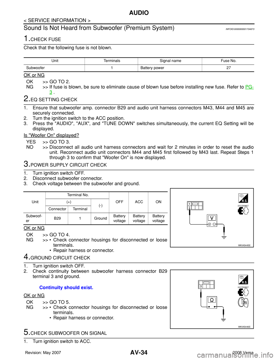
3.POWER SUPPLY CIRCUIT CHECK
1. Turn ignition switch OFF.
2. Disconnect subwoofer connector.
3. Check voltage between the subwoofer and ground.
OK or NG
OK >> GO TO 4.
NG >> • Check connector housings for disconnected or loose
terminals.
• Repair harness or connector.
4.GROUND CIRCUIT CHECK
1. Turn ignition switch OFF.
2. Check continuity between subwoofer harness connector B29
terminal 3 and ground.
OK or NG
OK >> GO TO 5.
NG >> • Check connector housings for disconnected or loose
terminals.
• Repair harness or connector.
5.CHECK SUBWOOFER ON SIGNAL
1. Turn ignition switch to ACC.
Unit Terminals Signal name Fuse No.
Subwoofer 1 Battery power 27
UnitTe r m i n a l N o .
OFF ACC ON (+)
(-)
Connector Terminal
Subwoof-
erB29 1 GroundBattery
voltageBattery
voltageBattery
voltage
WKIA5445E
Continuity should exist.
WKIA5446E
Page 432 of 2771

BCS-16
< SERVICE INFORMATION >
BCM (BODY CONTROL MODULE)
OK >> GO TO 3.
NG >> Repair or replace the harness.
3.CHECK GROUND CIRCUIT
Check continuity between BCM connector M20 terminal 67 and
ground.
OK or NG
OK >> Power supply and ground circuit is OK.
NG >> Repair or replace harness.
CONSULT-III Function (BCM)INFOID:0000000001704590
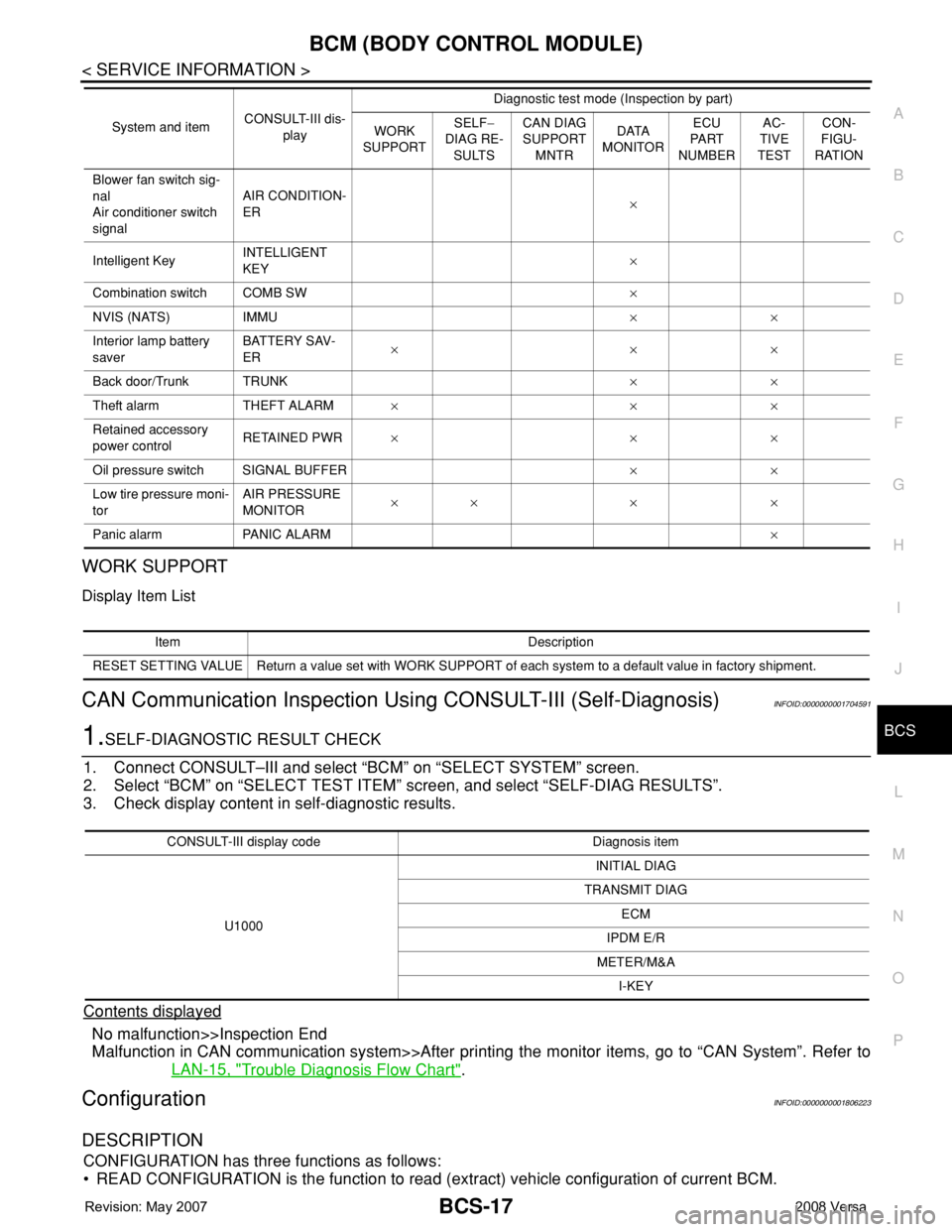
CONSULT-III can display each diagnostic item using the diagnostic test modes shown following.
ITEMS OF EACH PART
NOTE:
CONSULT-III will only display systems the vehicle possesses.67 - Ground : Continuity should exist.
LIIA0915E
BCM diagnostic
test itemDiagnostic mode Content
Inspection by partWORK SUPPORTSupports inspections and adjustments. Commands are transmitted to the BCM for
setting the status suitable for required operation, input/output signals are received
from the BCM and received data is displayed.
DATA MONITOR Displays BCM input/output data in real time.
ACTIVE TEST Operation of electrical loads can be checked by sending drive signal to them.
SELF-DIAG RESULTS Displays BCM self-diagnosis results.
CAN DIAG SUPPORT
MNTRThe results of transmit/receive diagnosis of CAN communication can be read.
ECU PART NUMBER BCM part number can be read.
CONFIGURATION Performs BCM configuration read/write functions.
System and itemCONSULT-III dis-
playDiagnostic test mode (Inspection by part)
WORK
SUPPORTSELF−
DIAG RE-
SULTSCAN DIAG
SUPPORT
MNTRDATA
MONITORECU
PA R T
NUMBERAC-
TIVE
TESTCON-
FIGU-
RATION
BCM BCM×× × × ×
Power door lock sys-
temDOOR LOCK×××
Rear defoggerREAR DEFOG-
GER××
Warning chime BUZZER××
Room lamp timer INT LAMP×××
Remote keyless entry
systemMULTI REMOTE
ENT×××
Headlamp HEAD LAMP×××
Wiper WIPER×××
Turn signal lamp
Hazard lampFLASHER××
Page 433 of 2771
BCM (BODY CONTROL MODULE)
BCS-17
< SERVICE INFORMATION >
C
D
E
F
G
H
I
J
L
MA
B
BCS
N
O
P
WORK SUPPORT
Display Item List
CAN Communication Inspection Using CONSULT-III (Self-Diagnosis)INFOID:0000000001704591
1.SELF-DIAGNOSTIC RESULT CHECK
1. Connect CONSULT–III and select “BCM” on “SELECT SYSTEM” screen.
2. Select “BCM” on “SELECT TEST ITEM” screen, and select “SELF-DIAG RESULTS”.
3. Check display content in self-diagnostic results.
Contents displayed
No malfunction>>Inspection End
Malfunction in CAN communication system>>After printing the monitor items, go to “CAN System”. Refer to
LAN-15, "
Trouble Diagnosis Flow Chart".
ConfigurationINFOID:0000000001806223
DESCRIPTION
CONFIGURATION has three functions as follows:
• READ CONFIGURATION is the function to read (extract) vehicle configuration of current BCM.
Blower fan switch sig-
nal
Air conditioner switch
signalAIR CONDITION-
ER×
Intelligent KeyINTELLIGENT
KEY×
Combination switch COMB SW×
NVIS (NATS) IMMU××
Interior lamp battery
saverBATTERY SAV-
ER×××
Back door/Trunk TRUNK××
Theft alarm THEFT ALARM×××
Retained accessory
power controlRETAINED PWR×××
Oil pressure switch SIGNAL BUFFER××
Low tire pressure moni-
torAIR PRESSURE
MONITOR×× × ×
Panic alarm PANIC ALARM× System and itemCONSULT-III dis-
playDiagnostic test mode (Inspection by part)
WORK
SUPPORTSELF−
DIAG RE-
SULTSCAN DIAG
SUPPORT
MNTRDATA
MONITORECU
PA R T
NUMBERAC-
TIVE
TESTCON-
FIGU-
RATION
Item Description
RESET SETTING VALUE Return a value set with WORK SUPPORT of each system to a default value in factory shipment.
CONSULT-III display code Diagnosis item
U1000INITIAL DIAG
TRANSMIT DIAG
ECM
IPDM E/R
METER/M&A
I-KEY
Page 434 of 2771

BCS-18
< SERVICE INFORMATION >
BCM (BODY CONTROL MODULE)
• WRITE CONFIGURATION-Manual selection is the function to select and write vehicle configuration on BCM
manually.
• WRITE CONFIGURATION-Config file is the function to write vehicle configuration with the data extracted
from current BCM.
• For READ CONFIGURATION and WRITE CONFIGURATION-Config file, refer to CONSULT-III Operation
Manual.
• For WRITE CONFIGURATION-Manual selection using the following flow chart, identify the correct model
and configuration list. Confirm and/or change setting value for each item according to the configuration list.
Depending on CONSULT-III software version being used, some or all of the write configuration items shown
in the following configuration lists may be displayed. If an item does not appear on the CONSULT-III WRITE
CONFIGURATION-Manual selection screen(s), then it is an auto setting item and it cannot be manually set
or changed.
NOTE:
Confirm vehicle model on IDENTIFICATION PLATE. Refer to GI-43, "
Model Variation".
CAUTION:
• When replacing BCM, you must perform WRITE CONFIGURATION with CONSULT-III.
• Complete the procedure of WRITE CONFIGURATION in order.
• If you set incorrect WRITE CONFIGURATION, incidents will occur.
• Configuration is different for each vehicle model. Confirm configuration of each vehicle model.
Removal and Installation of BCMINFOID:0000000001704593
REMOVAL
1. Remove the glove box. Refer to IP-11, "Removal and Installation".
2. Remove the BCM screws, disconnect the connectors and
remove the BCM (1).
INSTALLATION
Installation is in the reverse order of removal.
NOTE:
• When replacing BCM, it must be configured. Refer to BCS-17, "
Configuration".
• When replacing BCM, perform initialization of NATS system and registration of all NATS ignition key IDs.
Refer to BL-210
.
• When replacing BCM, if new BCM does not come with keyfobs attached, all existing keyfobs must be re-reg-
istered.
ITEM SET VAL
KEYLESS ENTRY WITH ⇔ WITHOUT
I-KEY WITH ⇔ WITHOUT
DTRL WITH ⇔ WITHOUT
THEFT ALARM WITH ⇔ WITHOUT
WKIA5672E