Page 2152 of 2771
HEADLAMP (FOR USA)
LT-15
< SERVICE INFORMATION >
C
D
E
F
G
H
I
J
L
MA
B
LT
N
O
P
OK or NG
OK >> GO TO 7.
NG >> GO TO 8.
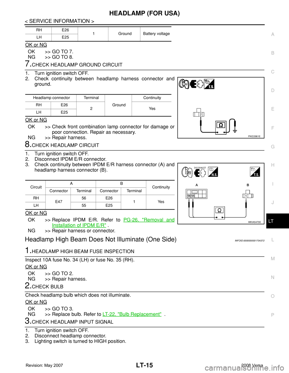
7.CHECK HEADLAMP GROUND CIRCUIT
1. Turn ignition switch OFF.
2. Check continuity between headlamp harness connector and
ground.
OK or NG
OK >> Check front combination lamp connector for damage or
poor connection. Repair as necessary.
NG >> Repair harness.
8.CHECK HEADLAMP CIRCUIT
1. Turn ignition switch OFF.
2. Disconnect IPDM E/R connector.
3. Check continuity between IPDM E/R harness connector (A) and
headlamp harness connector (B).
OK or NG
OK >> Replace IPDM E/R. Refer to PG-26, "Removal and
Installation of IPDM E/R" .
NG >> Repair harness or connector.
Headlamp High Beam Does Not Illuminate (One Side)INFOID:0000000001704372
1.HEADLAMP HIGH BEAM FUSE INSPECTION
Inspect 10A fuse No. 34 (LH) or fuse No. 35 (RH).
OK or NG
OK >> GO TO 2.
NG >> Repair harness.
2.CHECK BULB
Check headlamp bulb which does not illuminate.
OK or NG
OK >> GO TO 3.
NG >> Replace bulb. Refer to LT-22, "
Bulb Replacement" .
3.CHECK HEADLAMP INPUT SIGNAL
1. Turn ignition switch OFF.
2. Disconnect headlamp connector.
3. Lighting switch is turned to HIGH position.
RH E26
1 Ground Battery voltage
LH E25
Headlamp connector Terminal
Ground Continuity
RH E26
2Yes
LH E25
PKIC0961E
CircuitAB
Continuity
Connector Terminal Connector Terminal
RH
E4756 E26
1 Yes
LH 55 E25
WKIA5470E
Page 2153 of 2771
LT-16
< SERVICE INFORMATION >
HEADLAMP (FOR USA)
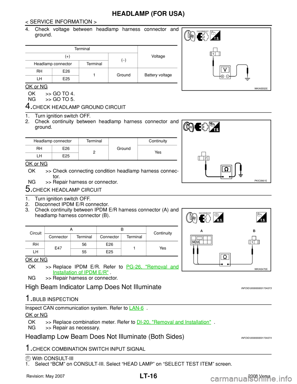
4. Check voltage between headlamp harness connector and
ground.
OK or NG
OK >> GO TO 4.
NG >> GO TO 5.
4.CHECK HEADLAMP GROUND CIRCUIT
1. Turn ignition switch OFF.
2. Check continuity between headlamp harness connector and
ground.
OK or NG
OK >> Check connecting condition headlamp harness connec-
tor.
NG >> Repair harness or connector.
5.CHECK HEADLAMP CIRCUIT
1. Turn ignition switch OFF.
2. Disconnect IPDM E/R connector.
3. Check continuity between IPDM E/R harness connector (A) and
headlamp harness connector (B).
OK or NG
OK >> Replace IPDM E/R. Refer to PG-26, "Removal and
Installation of IPDM E/R" .
NG >> Repair harness or connector.
High Beam Indicator Lamp Does Not IlluminateINFOID:0000000001704373
1.BULB INSPECTION
Inspect CAN communication system. Refer to LAN-6
.
OK or NG
OK >> Replace combination meter. Refer to DI-20, "Removal and Installation" .
NG >> Repair as necessary.
Headlamp Low Beam Does Not Illuminate (Both Sides)INFOID:0000000001704374
1.CHECK COMBINATION SWITCH INPUT SIGNAL
With CONSULT-III
1. Select “BCM” on CONSULT-III. Select “HEAD LAMP” on “SELECT TEST ITEM” screen.
Te r m i n a l
Voltag e (+)
(−)
Headlamp connector Terminal
RH E26
1 Ground Battery voltage
LH E25
WKIA5552E
Headlamp connector Terminal
Ground Continuity
RH E26
2Yes
LH E25
PKIC0961E
CircuitAB
Continuity
Connector Terminal Connector Terminal
RH
E47 56 E26
1Yes
LH 55 E25
WKIA5470E
Page 2155 of 2771
LT-18
< SERVICE INFORMATION >
HEADLAMP (FOR USA)
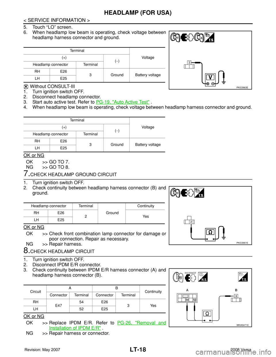
5. Touch “LO” screen.
6. When headlamp low beam is operating, check voltage between
headlamp harness connector and ground.
Without CONSULT-III
1. Turn ignition switch OFF.
2. Disconnect headlamp connector.
3. Start auto active test. Refer to PG-19, "
Auto Active Test" .
4. When headlamp low beam is operating, check voltage between headlamp harness connector and ground.
OK or NG
OK >> GO TO 7.
NG >> GO TO 8.
7.CHECK HEADLAMP GROUND CIRCUIT
1. Turn ignition switch OFF.
2. Check continuity between headlamp harness connector (B) and
ground.
OK or NG
OK >> Check front combination lamp connector for damage or
poor connection. Repair as necessary.
NG >> Repair harness.
8.CHECK HEADLAMP CIRCUIT
1. Turn ignition switch OFF.
2. Disconnect IPDM E/R connector.
3. Check continuity between IPDM E/R harness connector (A) and
headlamp harness connector (B).
OK or NG
OK >> Replace IPDM E/R. Refer to PG-26, "Removal and
Installation of IPDM E/R" .
NG >> Repair harness or connector.
Te r m i n a l
Vo l ta g e (+)
(−)
Headlamp connector Terminal
RH E26
3 Ground Battery voltage
LH E25
Te r m i n a l
Vo l ta g e (+)
(−)
Headlamp connector Terminal
RH E26
3 Ground Battery voltage
LH E25
PKIC0963E
Headlamp connector Terminal
Ground Continuity
RH E26
2Yes
LH E25
PKIC0961E
CircuitAB
Continuity
Connector Terminal Connector Terminal
RH
E4754 E26
3Yes
LH 52 E25
WKIA5471E
Page 2156 of 2771
HEADLAMP (FOR USA)
LT-19
< SERVICE INFORMATION >
C
D
E
F
G
H
I
J
L
MA
B
LT
N
O
P
Headlamp Low Beam Does Not Illuminate (One Side)INFOID:0000000001704375
1.HEADLAMP LOW BEAM FUSE INSPECTION
Inspect 15A fuse No. 40 (LH) and fuse No. 41 (RH).
OK or NG
OK >> GO TO 2.
NG >> Repair harness.
2.CHECK BULB
Check bulb of headlamp which does not illuminate.
OK or NG
OK >> GO TO 3.
NG >> Replace bulb. Refer to LT-22, "
Bulb Replacement" .
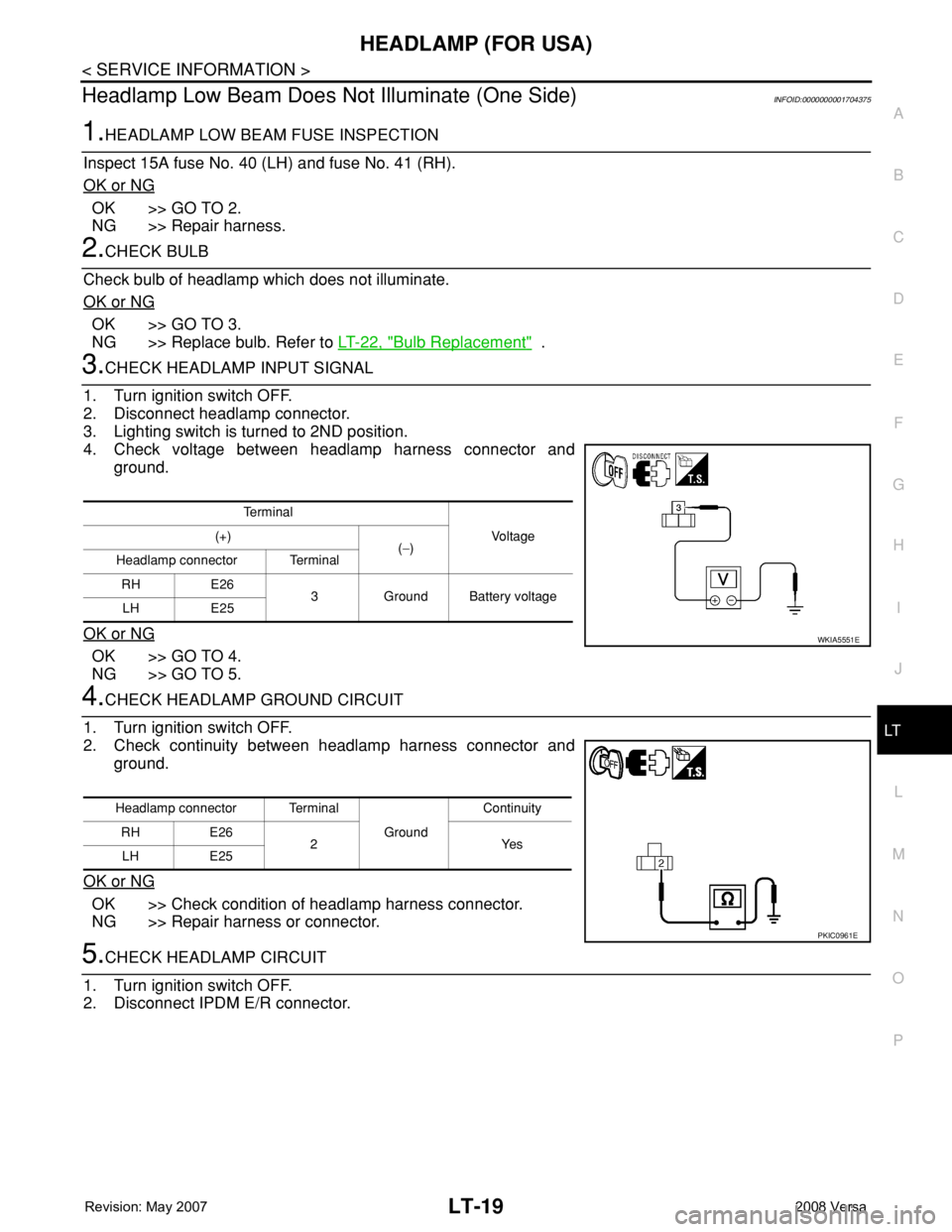
3.CHECK HEADLAMP INPUT SIGNAL
1. Turn ignition switch OFF.
2. Disconnect headlamp connector.
3. Lighting switch is turned to 2ND position.
4. Check voltage between headlamp harness connector and
ground.
OK or NG
OK >> GO TO 4.
NG >> GO TO 5.
4.CHECK HEADLAMP GROUND CIRCUIT
1. Turn ignition switch OFF.
2. Check continuity between headlamp harness connector and
ground.
OK or NG
OK >> Check condition of headlamp harness connector.
NG >> Repair harness or connector.
5.CHECK HEADLAMP CIRCUIT
1. Turn ignition switch OFF.
2. Disconnect IPDM E/R connector.
Te r m i n a l
Vo l ta g e (+)
(−)
Headlamp connector Terminal
RH E26
3 Ground Battery voltage
LH E25
WKIA5551E
Headlamp connector Terminal
Ground Continuity
RH E26
2Yes
LH E25
PKIC0961E
Page 2160 of 2771
HEADLAMP (FOR USA)
LT-23
< SERVICE INFORMATION >
C
D
E
F
G
H
I
J
L
MA
B
LT
N
O
P
2. Remove the headlamp. Refer to LT-23, "Removal and Installation".
3. Turn bulb socket counterclockwise and unlock it.
4. Remove bulb from its socket.
FRONT TURN SIGNAL LAMP
1. Turn lighting switch OFF.
2. Remove the headlamp. Refer to LT-23, "
Removal and Installation".
3. Turn bulb socket counterclockwise and unlock it.
4. Remove bulb from its socket.
Removal and InstallationINFOID:0000000001704379
REMOVAL
1. Disconnect the negative battery terminal.
2. Remove front bumper fascia. Refer to EI-14
.
3. Remove headlamp bolts (A).
4. Pull headlamp (1) toward the vehicle front, disconnect connec-
tor, and remove headlamp.
INSTALLATION
Installation is in the reverse order of removal.
• After installation, perform aiming adjustment. Refer to LT-21, "
Aiming Adjustment".
Disassembly and AssemblyINFOID:0000000001704380
PKIC1223E
WKIA5418E
Page 2164 of 2771
HEADLAMP (FOR CANADA) - DAYTIME LIGHT SYSTEM -
LT-27
< SERVICE INFORMATION >
C
D
E
F
G
H
I
J
L
MA
B
LT
N
O
P
• to IPDM E/R terminal 56,
• through 10A fuse (No. 34, located in IPDM E/R) and
• through both de-energized headlamp high relays
• to 10A fuse (No. 35, located in IPDM E/R),
• through IPDM E/R terminal 55
• to front combination lamp LH terminal high beam 1.
Ground is supplied
• to front combination lamp LH terminal 2
• through grounds E15 and E24,
• to daytime light relay 1 terminal 1
• through IPDM E/R terminal 6.
With power and ground supplied, high beam headlamps illuminate at reduced intensity.
COMBINATION SWITCH READING FUNCTION
Refer to BCS-3, "System Description" .
EXTERIOR LAMP BATTERY SAVER CONTROL
Refer to LT-72, "System Description" .
CAN Communication System DescriptionINFOID:0000000001704383
Refer to LAN-6, "System Description" .
Page 2170 of 2771
HEADLAMP (FOR CANADA) - DAYTIME LIGHT SYSTEM -
LT-33
< SERVICE INFORMATION >
C
D
E
F
G
H
I
J
L
MA
B
LT
N
O
P
How to Perform Trouble DiagnosisINFOID:0000000001704388
1. Confirm the symptom or customer complaint.
2. Understand operation, description and function description. Refer to LT-25, "
System Description" .
3. Perform the Preliminary Check. Refer to LT-33, "
Preliminary Check" .
4. Check symptom and repair or replace the cause of the malfunction.
5. Does the daytime light system operate normally? If YES, GO TO 6. If NO, GO TO 4.
6. INSPECTION END
Preliminary CheckINFOID:0000000001704389
CHECK BCM CONFIGURATION
1.CHECK BCM CONFIGURATION
Confirm BCM configuration for "DTRL" is set to "WITH". Refer to BCS-17, "
Configuration" .
OK or NG
OK >> Continue preliminary check. Refer to BCS-15, "BCM Power Supply and Ground Circuit Inspec-
tion" .
NG >> Change BCM configuration for "DTRL" to "WITH". Refer to BCS-17, "
Configuration" .
CHECK POWER SUPPLY AND GROUND CIRCUIT FOR BCM
Refer to BCS-15, "BCM Power Supply and Ground Circuit Inspection" .
CHECK POWER SUPPLY AND GROUND CIRCUIT FOR IPDM E/R
Refer to PG-25, "IPDM E/R Power/Ground Circuit Inspection" .
CONSULT-III Function (BCM)INFOID:0000000001704390
Refer to LT- 11 , "CONSULT-III Function (BCM)" .
CONSULT-III Function (IPDM E/R)INFOID:0000000001704391
Refer to LT-12, "CONSULT-III Function (IPDM E/R)" .
Daytime Light Control Does Not Operate Properly (High Beam Headlamps Operate
Properly)
INFOID:0000000001704392
1.CHECK DAYTIME LIGHT RELAY 1 FUSE
Inspect daytime light relay fuse 10A fuse (No. 26, located in the fuse and fusible link box).
OK or NG
OK >> GO TO 2.
NG >> Repair harness.
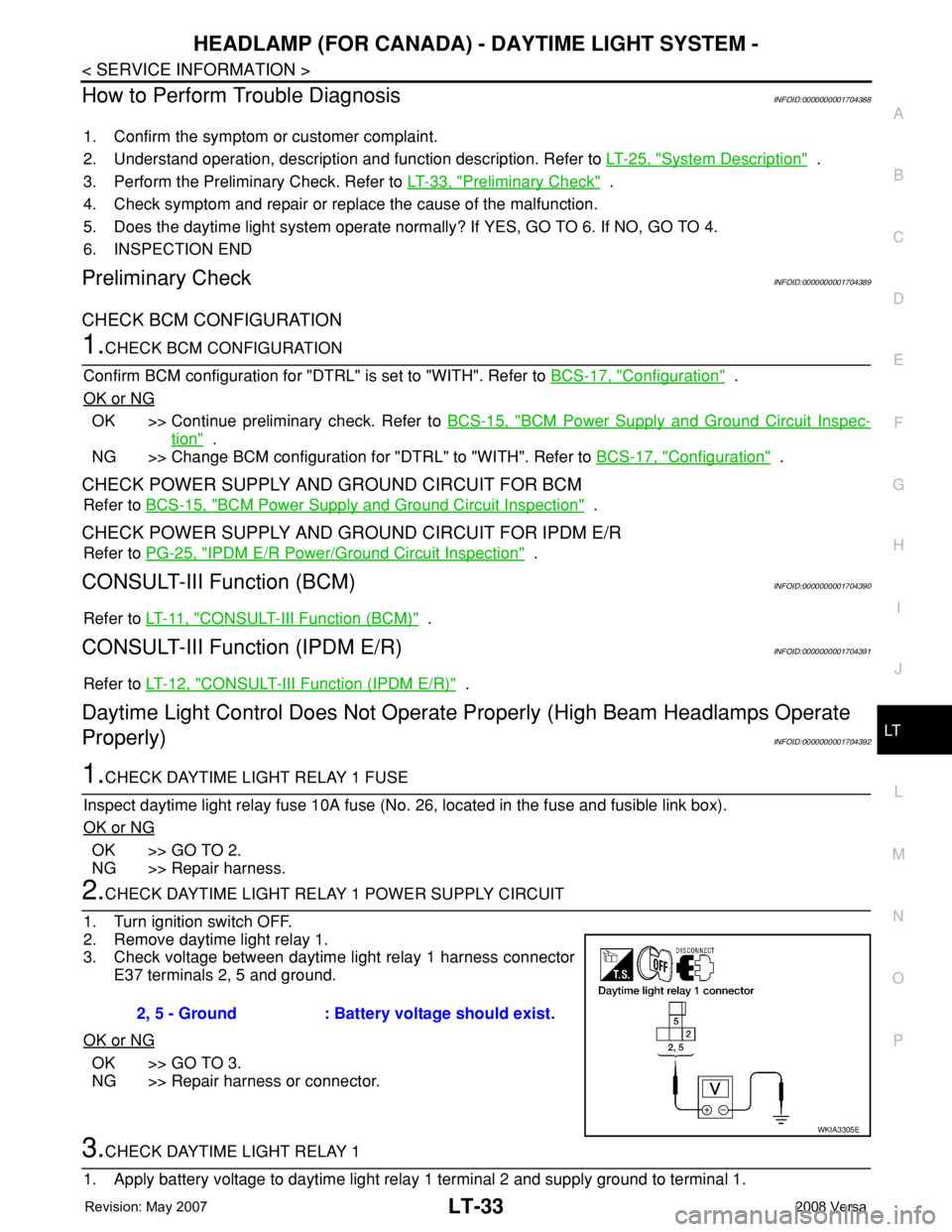
2.CHECK DAYTIME LIGHT RELAY 1 POWER SUPPLY CIRCUIT
1. Turn ignition switch OFF.
2. Remove daytime light relay 1.
3. Check voltage between daytime light relay 1 harness connector
E37 terminals 2, 5 and ground.
OK or NG
OK >> GO TO 3.
NG >> Repair harness or connector.
3.CHECK DAYTIME LIGHT RELAY 1
1. Apply battery voltage to daytime light relay 1 terminal 2 and supply ground to terminal 1.2, 5 - Ground : Battery voltage should exist.
WKIA3305E
Page 2174 of 2771
HEADLAMP (FOR CANADA) - DAYTIME LIGHT SYSTEM -
LT-37
< SERVICE INFORMATION >
C
D
E
F
G
H
I
J
L
MA
B
LT
N
O
P
2. Remove the headlamp. Refer to LT-23, "Removal and Installation".
3. Turn bulb socket counterclockwise and unlock it.
4. Remove bulb from its socket.
FRONT TURN SIGNAL LAMP
1. Turn lighting switch OFF.
2. Remove the headlamp. Refer to LT-23, "
Removal and Installation".
3. Turn bulb socket counterclockwise and unlock it.
4. Remove bulb from its socket.
Removal and InstallationINFOID:0000000001704395
REMOVAL
1. Disconnect the negative battery terminal.
2. Remove front bumper fascia. Refer to EI-14
.
3. Remove headlamp bolts (A).
4. Pull headlamp (1) toward the vehicle front, disconnect connec-
tor, and remove headlamp.
INSTALLATION
Installation is in the reverse order of removal.
• After installation, perform aiming adjustment. Refer to LT-35, "
Aiming Adjustment".
Disassembly and AssemblyINFOID:0000000001704396
PKIC1223E
WKIA5418E