2008 NISSAN LATIO turn signal
[x] Cancel search: turn signalPage 2450 of 2771
IPDM E/R (INTELLIGENT POWER DISTRIBUTION MODULE ENGINE ROOM)
PG-17
< SERVICE INFORMATION >
C
D
E
F
G
H
I
J
L
MA
B
PG
N
O
P
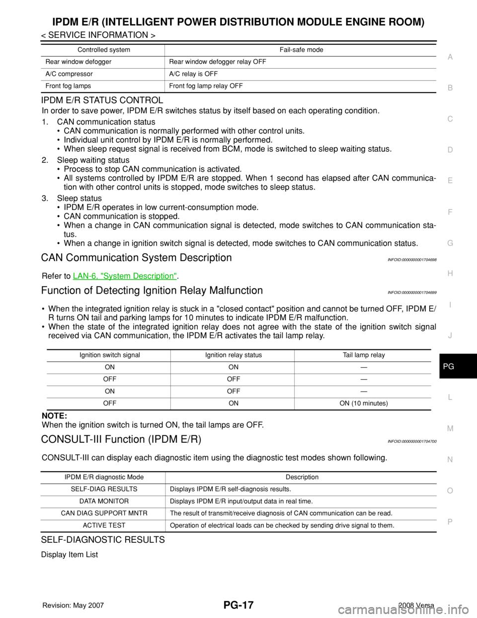
IPDM E/R STATUS CONTROL
In order to save power, IPDM E/R switches status by itself based on each operating condition.
1. CAN communication status
• CAN communication is normally performed with other control units.
• Individual unit control by IPDM E/R is normally performed.
• When sleep request signal is received from BCM, mode is switched to sleep waiting status.
2. Sleep waiting status
• Process to stop CAN communication is activated.
• All systems controlled by IPDM E/R are stopped. When 1 second has elapsed after CAN communica-
tion with other control units is stopped, mode switches to sleep status.
3. Sleep status
• IPDM E/R operates in low current-consumption mode.
• CAN communication is stopped.
• When a change in CAN communication signal is detected, mode switches to CAN communication sta-
tus.
• When a change in ignition switch signal is detected, mode switches to CAN communication status.
CAN Communication System DescriptionINFOID:0000000001704698
Refer to LAN-6, "System Description".
Function of Detecting Ignition Relay MalfunctionINFOID:0000000001704699
• When the integrated ignition relay is stuck in a "closed contact" position and cannot be turned OFF, IPDM E/
R turns ON tail and parking lamps for 10 minutes to indicate IPDM E/R malfunction.
• When the state of the integrated ignition relay does not agree with the state of the ignition switch signal
received via CAN communication, the IPDM E/R activates the tail lamp relay.
NOTE:
When the ignition switch is turned ON, the tail lamps are OFF.
CONSULT-III Function (IPDM E/R)INFOID:0000000001704700
CONSULT-III can display each diagnostic item using the diagnostic test modes shown following.
SELF-DIAGNOSTIC RESULTS
Display Item List
Rear window defogger Rear window defogger relay OFF
A/C compressor A/C relay is OFF
Front fog lamps Front fog lamp relay OFFControlled system Fail-safe mode
Ignition switch signal Ignition relay status Tail lamp relay
ON ON —
OFF OFF —
ON OFF —
OFF ON ON (10 minutes)
IPDM E/R diagnostic Mode Description
SELF-DIAG RESULTS Displays IPDM E/R self-diagnosis results.
DATA MONITOR Displays IPDM E/R input/output data in real time.
CAN DIAG SUPPORT MNTR The result of transmit/receive diagnosis of CAN communication can be read.
ACTIVE TEST Operation of electrical loads can be checked by sending drive signal to them.
Page 2452 of 2771
IPDM E/R (INTELLIGENT POWER DISTRIBUTION MODULE ENGINE ROOM)
PG-19
< SERVICE INFORMATION >
C
D
E
F
G
H
I
J
L
MA
B
PG
N
O
P
*1 Perform monitoring of IPDM E/R data with the ignition switch ON. When the ignition switch is in ACC position, display may not be cor-
rect.
*2 This item is displayed, but does not function.
CAN DIAG SUPPORT MNTR
Refer to LAN-8 .
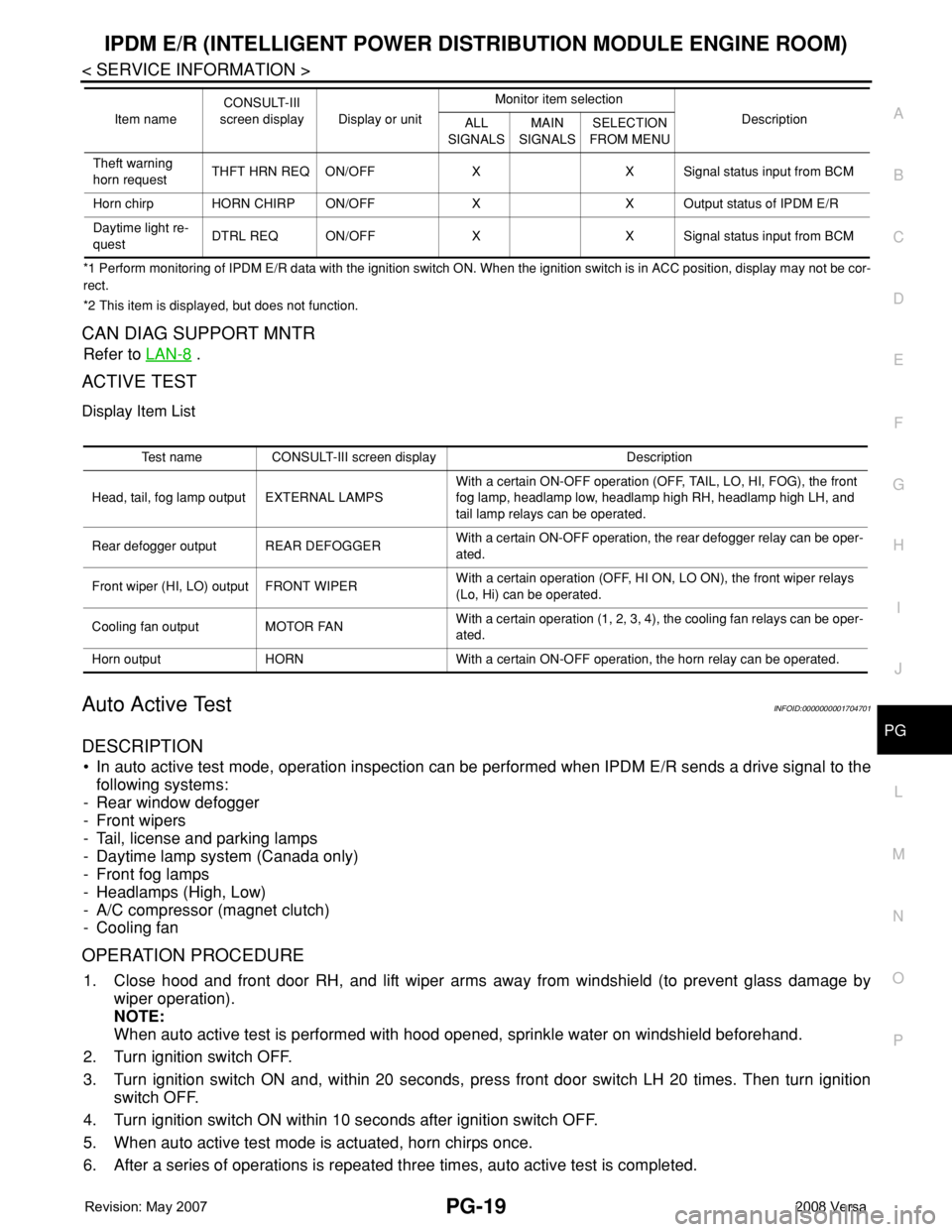
ACTIVE TEST
Display Item List
Auto Active TestINFOID:0000000001704701
DESCRIPTION
• In auto active test mode, operation inspection can be performed when IPDM E/R sends a drive signal to the
following systems:
- Rear window defogger
- Front wipers
- Tail, license and parking lamps
- Daytime lamp system (Canada only)
- Front fog lamps
- Headlamps (High, Low)
- A/C compressor (magnet clutch)
- Cooling fan
OPERATION PROCEDURE
1. Close hood and front door RH, and lift wiper arms away from windshield (to prevent glass damage by
wiper operation).
NOTE:
When auto active test is performed with hood opened, sprinkle water on windshield beforehand.
2. Turn ignition switch OFF.
3. Turn ignition switch ON and, within 20 seconds, press front door switch LH 20 times. Then turn ignition
switch OFF.
4. Turn ignition switch ON within 10 seconds after ignition switch OFF.
5. When auto active test mode is actuated, horn chirps once.
6. After a series of operations is repeated three times, auto active test is completed.
Theft warning
horn requestTHFT HRN REQ ON/OFF X X Signal status input from BCM
Horn chirp HORN CHIRP ON/OFF X X Output status of IPDM E/R
Daytime light re-
questDTRL REQ ON/OFF X X Signal status input from BCM Item nameCONSULT-III
screen display Display or unitMonitor item selection
Description
ALL
SIGNALSMAIN
SIGNALSSELECTION
FROM MENU
Test name CONSULT-III screen display Description
Head, tail, fog lamp output EXTERNAL LAMPSWith a certain ON-OFF operation (OFF, TAIL, LO, HI, FOG), the front
fog lamp, headlamp low, headlamp high RH, headlamp high LH, and
tail lamp relays can be operated.
Rear defogger output REAR DEFOGGERWith a certain ON-OFF operation, the rear defogger relay can be oper-
ated.
Front wiper (HI, LO) output FRONT WIPERWith a certain operation (OFF, HI ON, LO ON), the front wiper relays
(Lo, Hi) can be operated.
Cooling fan output MOTOR FANWith a certain operation (1, 2, 3, 4), the cooling fan relays can be oper-
ated.
Horn output HORN With a certain ON-OFF operation, the horn relay can be operated.
Page 2458 of 2771
IPDM E/R (INTELLIGENT POWER DISTRIBUTION MODULE ENGINE ROOM)
PG-25
< SERVICE INFORMATION >
C
D
E
F
G
H
I
J
L
MA
B
PG
N
O
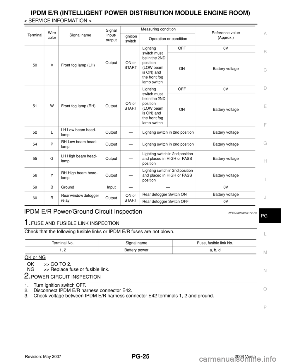
PIPDM E/R Power/Ground Circuit InspectionINFOID:0000000001704704
1.FUSE AND FUSIBLE LINK INSPECTION
Check that the following fusible links or IPDM E/R fuses are not blown.
OK or NG
OK >> GO TO 2.
NG >> Replace fuse or fusible link.
2.POWER CIRCUIT INSPECTION
1. Turn ignition switch OFF.
2. Disconnect IPDM E/R harness connector E42.
3. Check voltage between IPDM E/R harness connector E42 terminals 1, 2 and ground.
50 V Front fog lamp (LH)Output ON or
STARTLighting
switch must
be in the 2ND
position
(LOW beam
is ON) and
the front fog
lamp switchOFF 0V
ON Battery voltage
51 W Front fog lamp (RH) OutputON or
STARTLighting
switch must
be in the 2ND
position
(LOW beam
is ON) and
the front fog
lamp switchOFF 0V
ON Battery voltage
52 LLH Low beam head-
lampOutput — Lighting switch in 2nd position Battery voltage
54 PRH Low beam head-
lampOutput — Lighting switch in 2nd position Battery voltage
55 GLH High beam head-
lampOutput —Lighting switch in 2nd position
and placed in HIGH or PASS
positionBattery voltage
56 YRH High beam head-
lampOutput —Lighting switch in 2nd position
and placed in HIGH or PASS
positionBattery voltage
59 B Ground Input — — 0V
60 RRear window defogger
relayOutputON or
STARTRear defogger Switch ON Battery voltage
Rear defogger Switch OFF 0V Te r m i n a lWire
colorSignal nameSignal
input/
outputMeasuring condition
Reference value
(Approx.) Ignition
switchOperation or condition
Terminal No. Signal name Fuse, fusible link No.
1, 2 Battery power a, b, d
Page 2474 of 2771

HARNESS
PG-41
< SERVICE INFORMATION >
C
D
E
F
G
H
I
J
L
MA
B
PG
N
O
P
C3 E6 — : Fuse and fusible link box D3 E53 B/2: Front combination lamp LH
(parking)
B1 E7 SMJ : To M69
D3 E8 SMJ : To F8
B4 E9 BR/2 : Fusible link box (battery)
B3 E10 GR/2 : Fusible link box (battery)
B1 E11 B/2 : To M78
A3 E12 B/6 : Accelerator pedal position sensor
A2 E13 B/2 : Stop lamp switch (with M/T)
A2 E13 W/4 : Stop lamp switch (without M/T)
D3 E14 — : Engine ground (crash zone sensor)
C2 E15 — : Engine ground
B2 E16 B/32 : ECM
C5 E18 B/1 : Horn (low)
C4 E19 GR/6 : To F33
D5 E20 B/1 : Horn (low)
D3 E25 B/3: Front combination lamp LH
(headlamp)
E4 E27 B/2 : Front fog lamp LH
D4 E29 B/2: Front combination lamp LH
(turn signal)
B1 E31 W/24 : TCM
B1 E32 GR/24 : TCM
A2 E34 BR/2 : Clutch interlock switch (with M/T)
A2 E35 BR/2 : ASCD clutch switch
A2 E36 BR/2 : ASCD brake switch
B4 E40 GR/2 : Brake fluid level switch
D3 E42 B/2: IPDM E/R (Intelligent Power Distribu-
tion Module Engine Room)
C3 E43 W/16: IPDM E/R (Intelligent Power Distribu-
tion Module Engine Room)
C3 E44 W/6: IPDM E/R (Intelligent Power Distribu-
tion Module Engine Room)
D3 E45 BR/12: IPDM E/R (Intelligent Power Distribu-
tion Module Engine Room)
D3 E46 W/12: IPDM E/R (Intelligent Power Distribu-
tion Module Engine Room)
Page 2475 of 2771
PG-42
< SERVICE INFORMATION >
HARNESS
ENGINE ROOM HARNESS (RH VIEW)
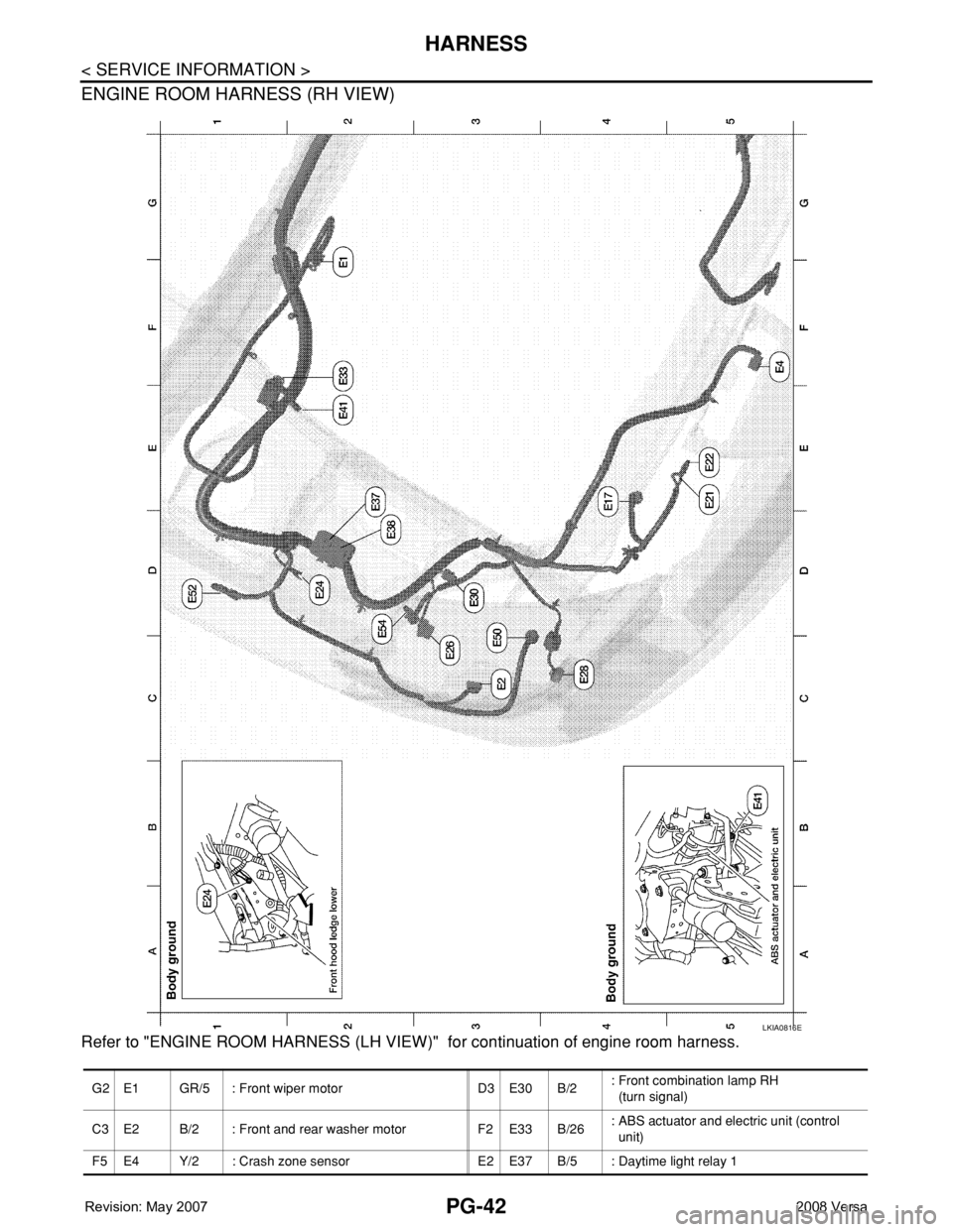
Refer to "ENGINE ROOM HARNESS (LH VIEW)" for continuation of engine room harness.
LKIA0816E
G2 E1 GR/5 : Front wiper motor D3 E30 B/2: Front combination lamp RH
(turn signal)
C3 E2 B/2 : Front and rear washer motor F2 E33 B/26: ABS actuator and electric unit (control
unit)
F5 E4 Y/2 : Crash zone sensor E2 E37 B/5 : Daytime light relay 1
Page 2493 of 2771

PG-60
< SERVICE INFORMATION >
HARNESS
SEN/PW EC Sensor Power Supply
SESCVT CVT Secondary Pressure Sensor Solenoid Valve
SHIFT AT A/T Shift Lock System
SHIFT CVT CVT Shift Lock System
SROOF RF Sunroof
SRS SRS Supplemental Restraint System
SSV/A AT Shift Solenoid Valve A
SSV/B AT Shift Solenoid Valve B
START SC Starting System
STM CVT Step Motor
STSIG CVT Start Signal Circuit
STOP/L LT Stop Lamp
TCV AT Torque Converter Clutch Solenoid Valve
TCV CVT Torque Converter Clutch Solenoid Valve
T/LID BL Trunk Lid Opener
T/WARN WT Low Tire Pressure Warning System
TAIL/L LT Parking, License and Tail Lamps
TPS1 EC Throttle Position Sensor
TPS2 EC Throttle Position Sensor
TPS3 EC Throttle Position Sensor
TURN LT Turn Signal and Hazard Warning Lamps
VEHSEC BL Vehicle Security (Theft Warning) System
VENT/V EC EVAP Canister Vent Control Valve
VSSA/T AT Vehicle Speed Sensor A/T (Revolution Sensor)
VSSMTR AT Vehicle Speed Sensor MTR
WARN DI Warning Lamps
WINDOW GW Power Window
WIP/R WW Rear Wiper and Washer
WIPER WW Front Wiper and Washer
Page 2541 of 2771
TROUBLE DIAGNOSIS
RF-11
< FUNCTION DIAGNOSIS >
C
D
E
F
G
H
J
K
L
MA
B
RF
N
O
P
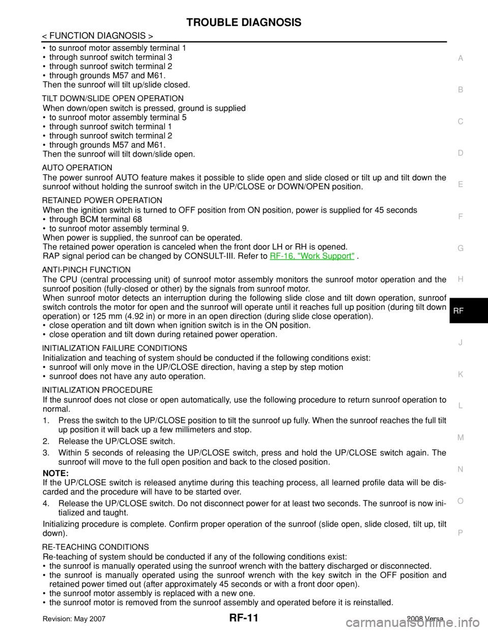
• to sunroof motor assembly terminal 1
• through sunroof switch terminal 3
• through sunroof switch terminal 2
• through grounds M57 and M61.
Then the sunroof will tilt up/slide closed.
TILT DOWN/SLIDE OPEN OPERATION
When down/open switch is pressed, ground is supplied
• to sunroof motor assembly terminal 5
• through sunroof switch terminal 1
• through sunroof switch terminal 2
• through grounds M57 and M61.
Then the sunroof will tilt down/slide open.
AUTO OPERATION
The power sunroof AUTO feature makes it possible to slide open and slide closed or tilt up and tilt down the
sunroof without holding the sunroof switch in the UP/CLOSE or DOWN/OPEN position.
RETAINED POWER OPERATION
When the ignition switch is turned to OFF position from ON position, power is supplied for 45 seconds
• through BCM terminal 68
• to sunroof motor assembly terminal 9.
When power is supplied, the sunroof can be operated.
The retained power operation is canceled when the front door LH or RH is opened.
RAP signal period can be changed by CONSULT-III. Refer to RF-16, "
Work Support" .
ANTI-PINCH FUNCTION
The CPU (central processing unit) of sunroof motor assembly monitors the sunroof motor operation and the
sunroof position (fully-closed or other) by the signals from sunroof motor.
When sunroof motor detects an interruption during the following slide close and tilt down operation, sunroof
switch controls the motor for open and the sunroof will operate until it reaches full up position (during tilt down
operation) or 125 mm (4.92 in) or more in an open direction (during slide close operation).
• close operation and tilt down when ignition switch is in the ON position.
• close operation and tilt down during retained power operation.
INITIALIZATION FAILURE CONDITIONS
Initialization and teaching of system should be conducted if the following conditions exist:
• sunroof will only move in the UP/CLOSE direction, having a step by step motion
• sunroof does not have any auto operation.
INITIALIZATION PROCEDURE
If the sunroof does not close or open automatically, use the following procedure to return sunroof operation to
normal.
1. Press the switch to the UP/CLOSE position to tilt the sunroof up fully. When the sunroof reaches the full tilt
up position it will back up a few millimeters and stop.
2. Release the UP/CLOSE switch.
3. Within 5 seconds of releasing the UP/CLOSE switch, press and hold the UP/CLOSE switch again. The
sunroof will move to the full open position and back to the closed position.
NOTE:
If the UP/CLOSE switch is released anytime during this teaching process, all learned profile data will be dis-
carded and the procedure will have to be started over.
4. Release the UP/CLOSE switch. Do not disconnect power for at least two seconds. The sunroof is now ini-
tialized and taught.
Initializing procedure is complete. Confirm proper operation of the sunroof (slide open, slide closed, tilt up, tilt
down).
RE-TEACHING CONDITIONS
Re-teaching of system should be conducted if any of the following conditions exist:
• the sunroof is manually operated using the sunroof wrench with the battery discharged or disconnected.
• the sunroof is manually operated using the sunroof wrench with the key switch in the OFF position and
retained power timed out (after approximately 45 seconds or with a front door open).
• the sunroof motor assembly is replaced with a new one.
• the sunroof motor is removed from the sunroof assembly and operated before it is reinstalled.
Page 2545 of 2771
TROUBLE DIAGNOSIS
RF-15
< FUNCTION DIAGNOSIS >
C
D
E
F
G
H
J
K
L
MA
B
RF
N
O
P
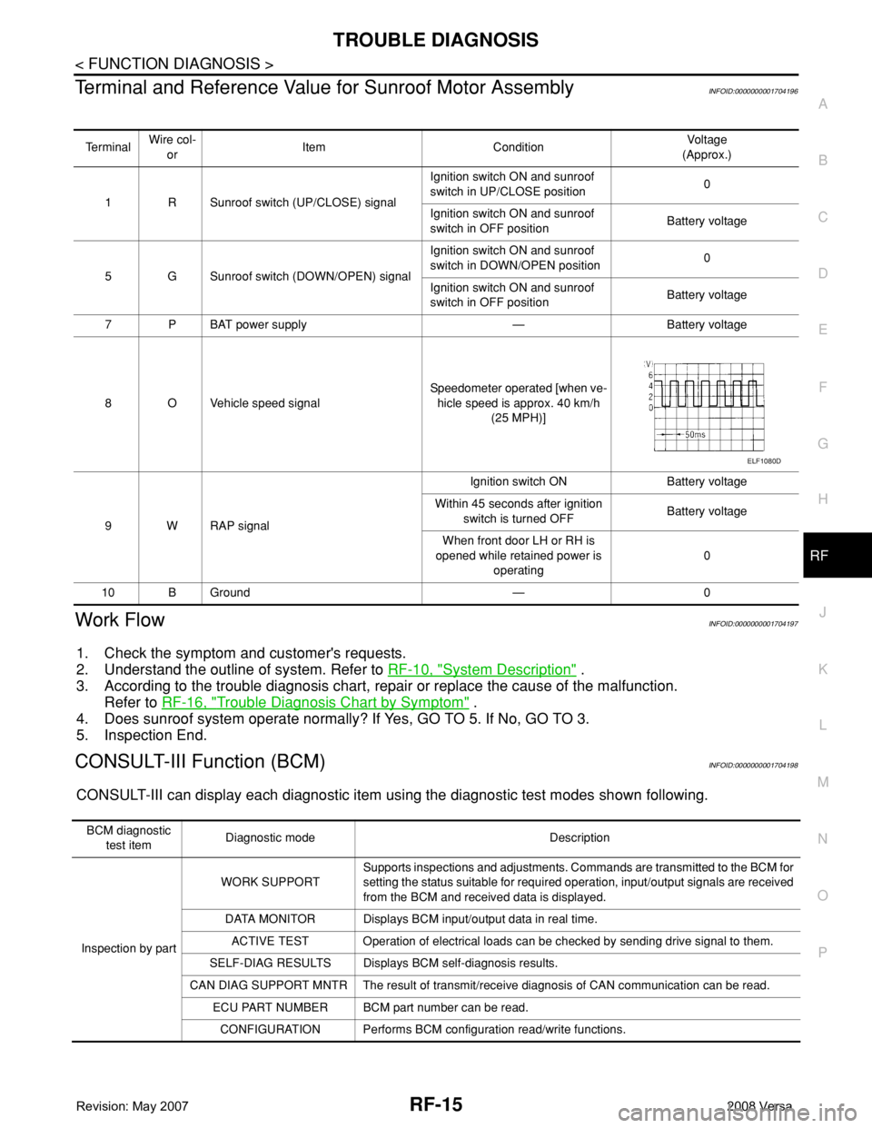
Terminal and Reference Value for Sunroof Motor AssemblyINFOID:0000000001704196
Work FlowINFOID:0000000001704197
1. Check the symptom and customer's requests.
2. Understand the outline of system. Refer to RF-10, "
System Description" .
3. According to the trouble diagnosis chart, repair or replace the cause of the malfunction.
Refer to RF-16, "
Trouble Diagnosis Chart by Symptom" .
4. Does sunroof system operate normally? If Yes, GO TO 5. If No, GO TO 3.
5. Inspection End.
CONSULT-III Function (BCM)INFOID:0000000001704198
CONSULT-III can display each diagnostic item using the diagnostic test modes shown following.
Te r m i n a lWire col-
orItem ConditionVoltag e
(Approx.)
1 R Sunroof switch (UP/CLOSE) signalIgnition switch ON and sunroof
switch in UP/CLOSE position0
Ignition switch ON and sunroof
switch in OFF positionBattery voltage
5 G Sunroof switch (DOWN/OPEN) signalIgnition switch ON and sunroof
switch in DOWN/OPEN position0
Ignition switch ON and sunroof
switch in OFF positionBattery voltage
7PBAT power supply — Battery voltage
8 O Vehicle speed signalSpeedometer operated [when ve-
hicle speed is approx. 40 km/h
(25 MPH)]
9 W RAP signalIgnition switch ON Battery voltage
Within 45 seconds after ignition
switch is turned OFFBattery voltage
When front door LH or RH is
opened while retained power is
operating0
10 B Ground — 0
ELF1080D
BCM diagnostic
test itemDiagnostic mode Description
Inspection by partWORK SUPPORTSupports inspections and adjustments. Commands are transmitted to the BCM for
setting the status suitable for required operation, input/output signals are received
from the BCM and received data is displayed.
DATA MONITOR Displays BCM input/output data in real time.
ACTIVE TEST Operation of electrical loads can be checked by sending drive signal to them.
SELF-DIAG RESULTS Displays BCM self-diagnosis results.
CAN DIAG SUPPORT MNTR The result of transmit/receive diagnosis of CAN communication can be read.
ECU PART NUMBER BCM part number can be read.
CONFIGURATION Performs BCM configuration read/write functions.