2008 NISSAN LATIO coolant temperature
[x] Cancel search: coolant temperaturePage 1197 of 2771

TROUBLE DIAGNOSIS
EC-123
< SERVICE INFORMATION >
C
D
E
F
G
H
I
J
K
L
MA
EC
N
P O
INT/V SOL (B1)• Engine: After warming up
• Air conditioner switch: OFF
• Shift lever: P or N (A/T, CVT),
Neutral (M/T)
•No loadIdle 0% - 2%
When revving engine up to 2,000 rpm
quicklyApprox. 0% - 90%
AIR COND RLY• Engine: After warming up, idle the
engineAir conditioner switch: OFF OFF
Air conditioner switch: ON
(Compressor operates)ON
FUEL PUMP RLY• For 1 second after turning ignition switch ON
• Engine running or crankingON
• Except above conditions OFF
VENT CONT/V • Ignition switch: ON OFF
THRTL RELAY • Ignition switch: ON ON
COOLING FAN• Engine: After warming up, idle the
engine
• Air conditioner switch: OFFEngine coolant temperature: 97°C
(207°F) or lessOFF
Engine coolant temperature: Between
98°C (208°F) and 99°C (210°F)LOW
Engine coolant temperature: 100°C
(212°F) or moreHIGH
HO2S2 HTR (B1)• Below 3,600 rpm after the following conditions are met.
- Engine: After warming up
- Keeping the engine speed between 3,500 and 4,000 rpm for 1 minute and
at idle for 1 minute under no loadON
• Engine speed: Above 3,600 rpm OFF
I/P PULLY SPD • Vehicle speed: More than 20 km/h (12 MPH)Almost the same speed as the
tachometer indication
VEHICLE SPEED• Turn drive wheels and compare CONSULT-II value with the speedometer
indication.Almost the same speed as the
speedometer indication
TRVL AFTER MIL • Ignition switch: ONVehicle has traveled after MIL has
turned ON.0 - 65,535 km
(0 - 40,723 mile)
A/F S1 HTR (B1)• Engine: After warming up, idle the engine
(More than 140 seconds after starting engine.)4 - 100%
AC PRESS SEN• Engine: Idle
• Air conditioner switch: ON (Compressor operates)1.0 - 4.0V
VHCL SPEED SE• Turn drive wheels and compare speedometer indication with the CONSULT-
II value.Almost the same speed as the
speedometer indication
SET VHCL SPD • Engine: Running ASCD: OperatingThe preset vehicle speed is
displayed.
MAIN SW • Ignition switch: ONMAIN switch: Pressed ON
MAIN switch: Released OFF
CANCEL SW • Ignition switch: ONCANCEL switch: Pressed ON
CANCEL switch: Released OFF
RESUME/ACC SW • Ignition switch: ONRESUME/ACCELERATE switch:
PressedON
RESUME/ACCELERATE switch: Re-
leased
OFF
SET SW • Ignition switch: ONSET/COAST switch: Pressed ON
SET/COAST switch: Released OFF MONITOR ITEM CONDITION SPECIFICATION
Page 1201 of 2771
TROUBLE DIAGNOSIS - SPECIFICATION VALUE
EC-127
< SERVICE INFORMATION >
C
D
E
F
G
H
I
J
K
L
MA
EC
N
P O
TROUBLE DIAGNOSIS - SPECIFICATION VALUE
DescriptionINFOID:0000000001702599
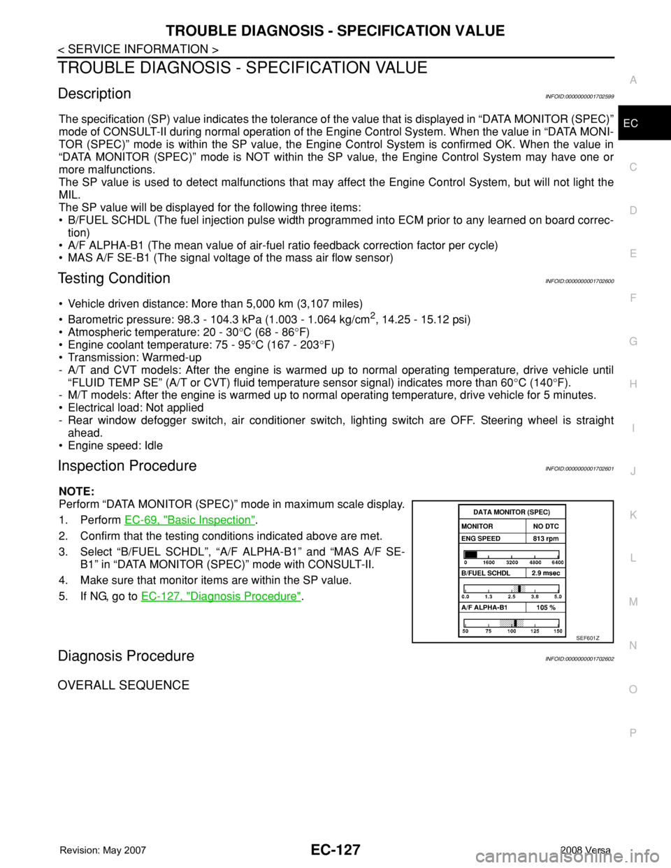
The specification (SP) value indicates the tolerance of the value that is displayed in “DATA MONITOR (SPEC)”
mode of CONSULT-II during normal operation of the Engine Control System. When the value in “DATA MONI-
TOR (SPEC)” mode is within the SP value, the Engine Control System is confirmed OK. When the value in
“DATA MONITOR (SPEC)” mode is NOT within the SP value, the Engine Control System may have one or
more malfunctions.
The SP value is used to detect malfunctions that may affect the Engine Control System, but will not light the
MIL.
The SP value will be displayed for the following three items:
• B/FUEL SCHDL (The fuel injection pulse width programmed into ECM prior to any learned on board correc-
tion)
• A/F ALPHA-B1 (The mean value of air-fuel ratio feedback correction factor per cycle)
• MAS A/F SE-B1 (The signal voltage of the mass air flow sensor)
Testing ConditionINFOID:0000000001702600
• Vehicle driven distance: More than 5,000 km (3,107 miles)
• Barometric pressure: 98.3 - 104.3 kPa (1.003 - 1.064 kg/cm
2, 14.25 - 15.12 psi)
• Atmospheric temperature: 20 - 30°C (68 - 86°F)
• Engine coolant temperature: 75 - 95°C (167 - 203°F)
• Transmission: Warmed-up
- A/T and CVT models: After the engine is warmed up to normal operating temperature, drive vehicle until
“FLUID TEMP SE” (A/T or CVT) fluid temperature sensor signal) indicates more than 60°C (140°F).
- M/T models: After the engine is warmed up to normal operating temperature, drive vehicle for 5 minutes.
• Electrical load: Not applied
- Rear window defogger switch, air conditioner switch, lighting switch are OFF. Steering wheel is straight
ahead.
• Engine speed: Idle
Inspection ProcedureINFOID:0000000001702601
NOTE:
Perform “DATA MONITOR (SPEC)” mode in maximum scale display.
1. Perform EC-69, "
Basic Inspection".
2. Confirm that the testing conditions indicated above are met.
3. Select “B/FUEL SCHDL”, “A/F ALPHA-B1” and “MAS A/F SE-
B1” in “DATA MONITOR (SPEC)” mode with CONSULT-II.
4. Make sure that monitor items are within the SP value.
5. If NG, go to EC-127, "
Diagnosis Procedure".
Diagnosis ProcedureINFOID:0000000001702602
OVERALL SEQUENCE
SEF601Z
Page 1221 of 2771
DTC P0011 IVT CONTROL
EC-147
< SERVICE INFORMATION >
C
D
E
F
G
H
I
J
K
L
MA
EC
N
P O
DTC P0011 IVT CONTROL
DescriptionINFOID:0000000001702617
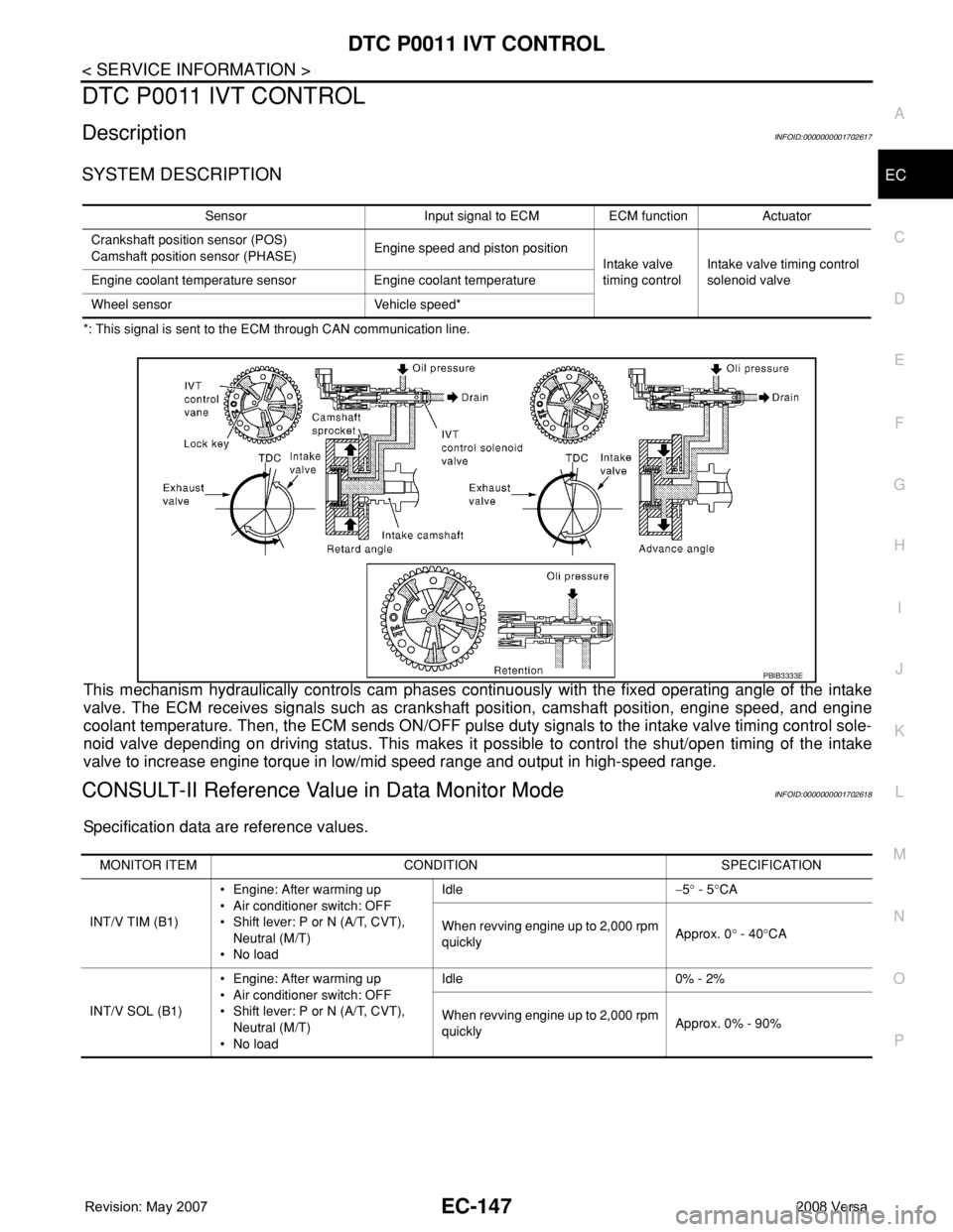
SYSTEM DESCRIPTION
*: This signal is sent to the ECM through CAN communication line.
This mechanism hydraulically controls cam phases continuously with the fixed operating angle of the intake
valve. The ECM receives signals such as crankshaft position, camshaft position, engine speed, and engine
coolant temperature. Then, the ECM sends ON/OFF pulse duty signals to the intake valve timing control sole-
noid valve depending on driving status. This makes it possible to control the shut/open timing of the intake
valve to increase engine torque in low/mid speed range and output in high-speed range.
CONSULT-II Reference Value in Data Monitor ModeINFOID:0000000001702618
Specification data are reference values.
Sensor Input signal to ECM ECM function Actuator
Crankshaft position sensor (POS)
Camshaft position sensor (PHASE)Engine speed and piston position
Intake valve
timing controlIntake valve timing control
solenoid valve Engine coolant temperature sensor Engine coolant temperature
Wheel sensor Vehicle speed*
PBIB3333E
MONITOR ITEM CONDITION SPECIFICATION
INT/V TIM (B1)• Engine: After warming up
• Air conditioner switch: OFF
• Shift lever: P or N (A/T, CVT),
Neutral (M/T)
•No loadIdle−5° - 5°CA
When revving engine up to 2,000 rpm
quicklyApprox. 0° - 40°CA
INT/V SOL (B1)• Engine: After warming up
• Air conditioner switch: OFF
• Shift lever: P or N (A/T, CVT),
Neutral (M/T)
•No loadIdle 0% - 2%
When revving engine up to 2,000 rpm
quicklyApprox. 0% - 90%
Page 1230 of 2771

EC-156
< SERVICE INFORMATION >
DTC P0037, P0038 HO2S2 HEATER
DTC P0037, P0038 HO2S2 HEATER
DescriptionINFOID:0000000001702632
SYSTEM DESCRIPTION
The ECM performs ON/OFF control of the heated oxygen sensor 2 heater corresponding to the engine speed,
amount of intake air and engine coolant temperature.
OPERATION
CONSULT-II Reference Value in Data Monitor ModeINFOID:0000000001702633
Specification data are reference values.
On Board Diagnosis LogicINFOID:0000000001702634
DTC Confirmation ProcedureINFOID:0000000001702635
NOTE:
If DTC Confirmation Procedure has been previously conducted, always turn ignition switch OFF and wait at
least 10 seconds before conducting the next test.
TESTING CONDITION:
Before performing the following procedure, confirm that battery voltage is between 10.5V and 16V at
idle.
WITH CONSULT-II
Sensor Input Signal to ECM ECM Function Actuator
Camshaft position sensor (PHASE)
Engine speed
Heated oxygen sensor 2
heater controlHeated oxygen sensor 2 heater Crankshaft position sensor (POS)
Engine coolant temperature sensorEngine coolant tempera-
ture
Mass air flow sensor Amount of intake air
Engine speed rpm Heated oxygen sensor 2 heater
Above 3,600OFF
• Below 3,600 rpm after the following conditions are met.
- Engine: After warming up
- Keeping the engine speed between 3,500 and 4,000 rpm for 1
minute and at idle for 1 minute under no loadON
MONITOR ITEM CONDITION SPECIFICATION
HO2S2 HTR (B1)• Engine speed: Below 3,600 rpm after the following conditions are met
- Engine: After warming up
- Keeping the engine speed between 3,500 and 4,000 rpm for 1 minute and
at idle for 1 minute under no load.ON
• Engine speed: Above 3,600 rpm OFF
DTC No.Trouble diagnosis
nameDTC detecting condition Possible cause
P0037
0037Heated oxygen
sensor 2 heater
control circuit lowThe current amperage in the heated oxygen sensor
2 heater circuit is out of the normal range.
(An excessively low voltage signal is sent to ECM
through the heated oxygen sensor 2 heater.)• Harness or connectors
(Heated oxygen sensor 2 heater circuit is
open or shorted.)
• Heated oxygen sensor 2 heater
P0038
0038Heated oxygen
sensor 2 heater
control circuit highThe current amperage in the heated oxygen sensor
2 heater circuit is out of the normal range.
(An excessively high voltage signal is sent to ECM
through the heated oxygen sensor 2 heater.)• Harness or connectors
(Heated oxygen sensor 2 heater circuit is
shorted.)
• Heated oxygen sensor 2 heater
Page 1261 of 2771
DTC P0117, P0118 ECT SENSOR
EC-187
< SERVICE INFORMATION >
C
D
E
F
G
H
I
J
K
L
MA
EC
N
P O
DTC P0117, P0118 ECT SENSOR
Component DescriptionINFOID:0000000001702672
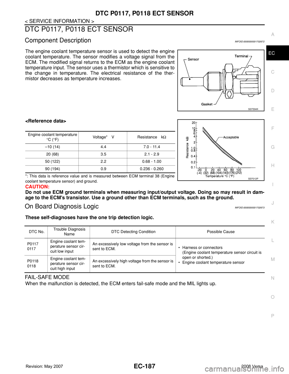
The engine coolant temperature sensor is used to detect the engine
coolant temperature. The sensor modifies a voltage signal from the
ECM. The modified signal returns to the ECM as the engine coolant
temperature input. The sensor uses a thermistor which is sensitive to
the change in temperature. The electrical resistance of the ther-
mistor decreases as temperature increases.
*: This data is reference value and is measured between ECM terminal 38 (Engine
coolant temperature sensor) and ground.
CAUTION:
Do not use ECM ground terminals when measuring input/output voltage. Doing so may result in dam-
age to the ECM's transistor. Use a ground other than ECM terminals, such as the ground.
On Board Diagnosis LogicINFOID:0000000001702673
These self-diagnoses have the one trip detection logic.
FAIL-SAFE MODE
When the malfunction is detected, the ECM enters fail-safe mode and the MIL lights up.
SEF594K
Engine coolant temperature
°C (°F)Voltage* V Resistance kΩ
–10 (14) 4.4 7.0 - 11.4
20 (68) 3.5 2.1 - 2.9
50 (122) 2.2 0.68 - 1.00
90 (194) 0.9 0.236 - 0.260
SEF012P
DTC No.Trouble Diagnosis
NameDTC Detecting Condition Possible Cause
P0117
0117Engine coolant tem-
perature sensor cir-
cuit low inputAn excessively low voltage from the sensor is
sent to ECM.• Harness or connectors
(Engine coolant temperature sensor circuit is
open or shorted.)
• Engine coolant temperature sensor P0118
0118Engine coolant tem-
perature sensor cir-
cuit high inputAn excessively high voltage from the sensor is
sent to ECM.
Page 1262 of 2771
EC-188
< SERVICE INFORMATION >
DTC P0117, P0118 ECT SENSOR
DTC Confirmation Procedure
INFOID:0000000001702674
NOTE:
If DTC Confirmation Procedure has been previously conducted, always turn ignition switch OFF and wait at
least 10 seconds before conducting the next test.
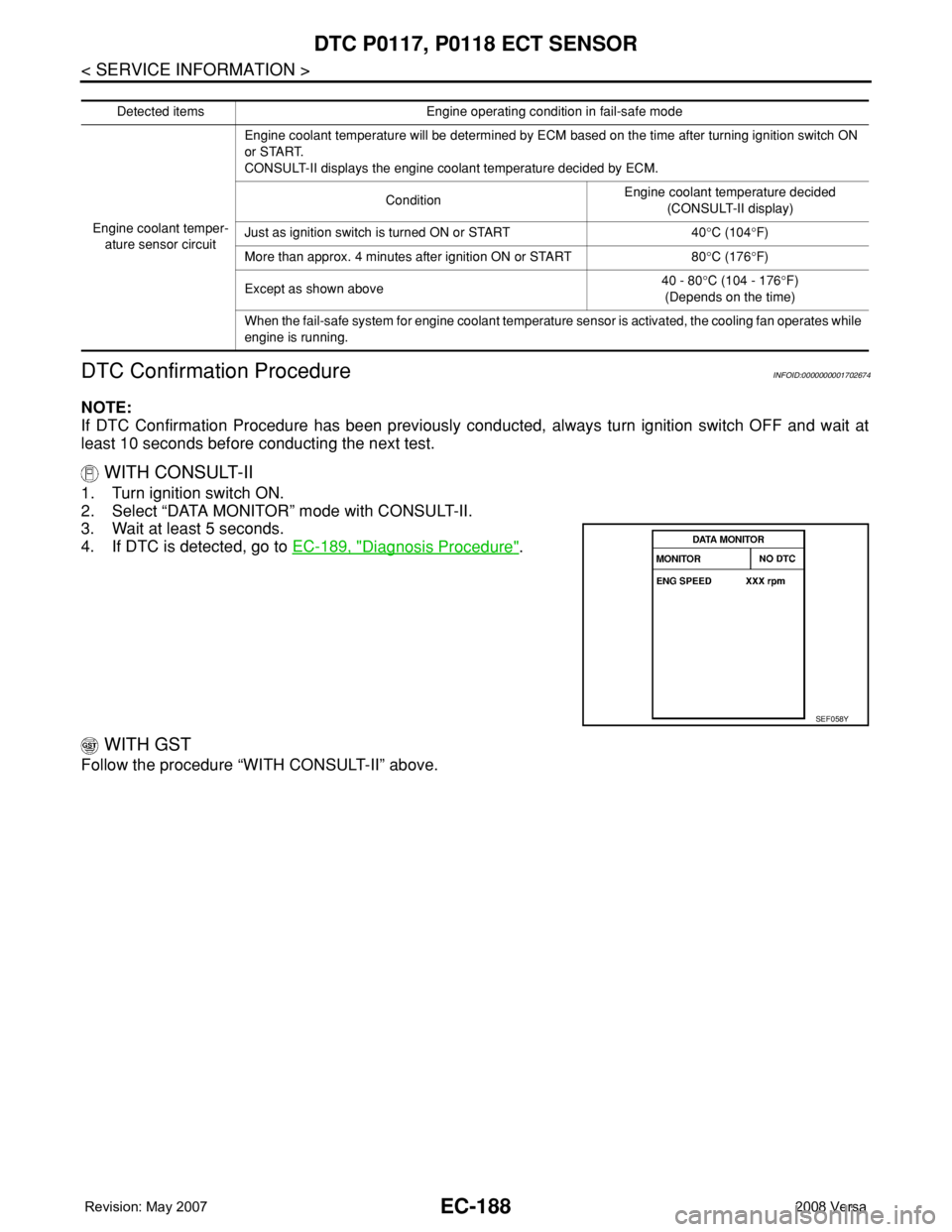
WITH CONSULT-II
1. Turn ignition switch ON.
2. Select “DATA MONITOR” mode with CONSULT-II.
3. Wait at least 5 seconds.
4. If DTC is detected, go to EC-189, "
Diagnosis Procedure".
WITH GST
Follow the procedure “WITH CONSULT-II” above.
Detected items Engine operating condition in fail-safe mode
Engine coolant temper-
ature sensor circuitEngine coolant temperature will be determined by ECM based on the time after turning ignition switch ON
or START.
CONSULT-II displays the engine coolant temperature decided by ECM.
ConditionEngine coolant temperature decided
(CONSULT-II display)
Just as ignition switch is turned ON or START 40°C (104°F)
More than approx. 4 minutes after ignition ON or START 80°C (176°F)
Except as shown above40 - 80°C (104 - 176°F)
(Depends on the time)
When the fail-safe system for engine coolant temperature sensor is activated, the cooling fan operates while
engine is running.
SEF058Y
Page 1264 of 2771
EC-190
< SERVICE INFORMATION >
DTC P0117, P0118 ECT SENSOR
OK or NG
OK >> GO TO 2.
NG >> Repair or replace ground connections.
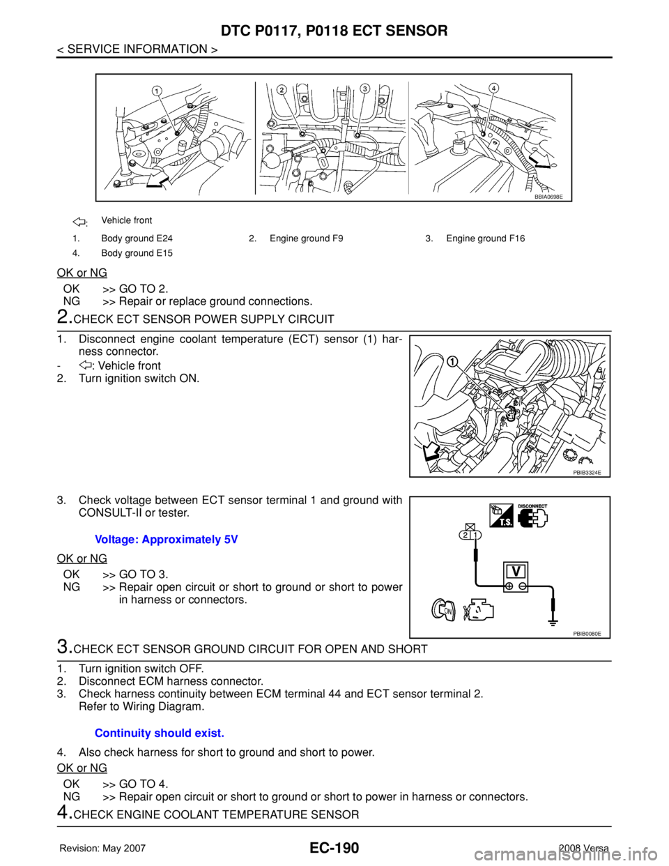
2.CHECK ECT SENSOR POWER SUPPLY CIRCUIT
1. Disconnect engine coolant temperature (ECT) sensor (1) har-
ness connector.
- : Vehicle front
2. Turn ignition switch ON.
3. Check voltage between ECT sensor terminal 1 and ground with
CONSULT-II or tester.
OK or NG
OK >> GO TO 3.
NG >> Repair open circuit or short to ground or short to power
in harness or connectors.
3.CHECK ECT SENSOR GROUND CIRCUIT FOR OPEN AND SHORT
1. Turn ignition switch OFF.
2. Disconnect ECM harness connector.
3. Check harness continuity between ECM terminal 44 and ECT sensor terminal 2.
Refer to Wiring Diagram.
4. Also check harness for short to ground and short to power.
OK or NG
OK >> GO TO 4.
NG >> Repair open circuit or short to ground or short to power in harness or connectors.
4.CHECK ENGINE COOLANT TEMPERATURE SENSOR
:Vehicle front
1. Body ground E24 2. Engine ground F9 3. Engine ground F16
4. Body ground E15
BBIA0698E
PBIB3324E
Voltage: Approximately 5V
PBIB0080E
Continuity should exist.
Page 1265 of 2771
DTC P0117, P0118 ECT SENSOR
EC-191
< SERVICE INFORMATION >
C
D
E
F
G
H
I
J
K
L
MA
EC
N
P O
Refer to EC-191, "Component Inspection".
OK or NG
OK >> GO TO 5.
NG >> Replace engine coolant temperature sensor.
5.CHECK INTERMITTENT INCIDENT
Refer to EC-136
.
>>INSPECTION END
Component InspectionINFOID:0000000001702677
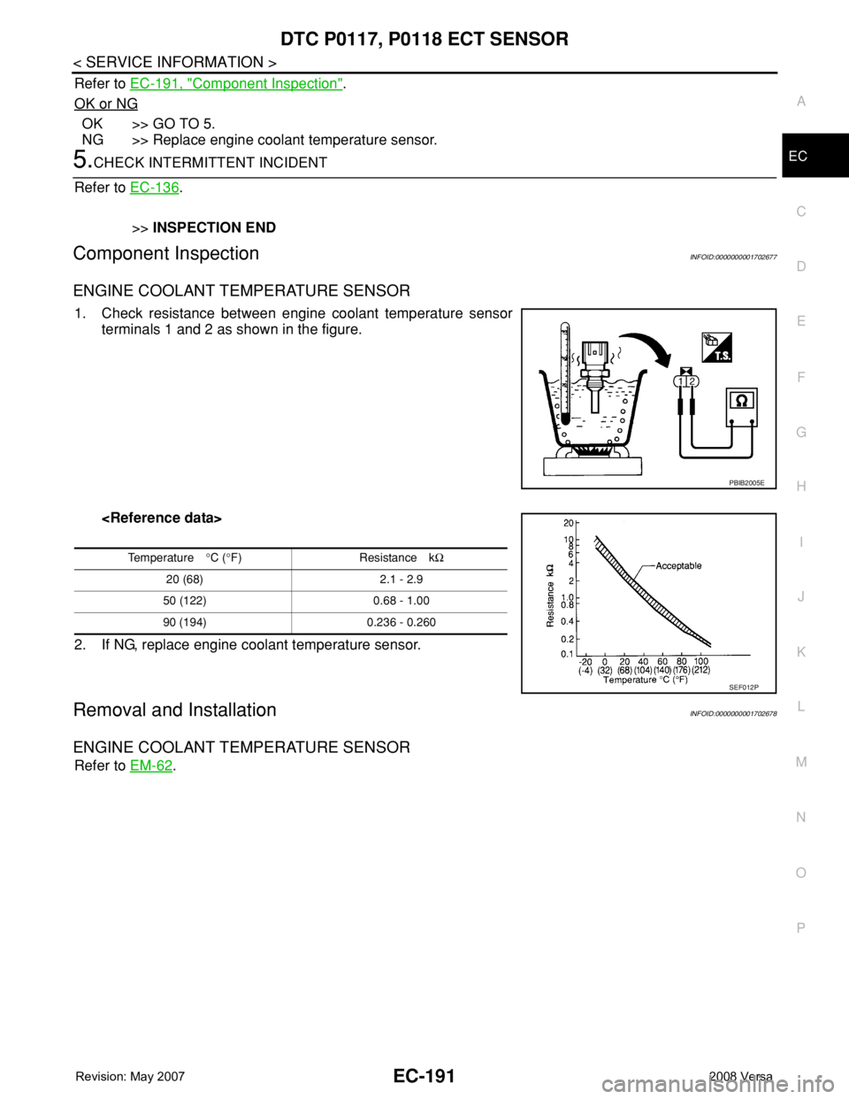
ENGINE COOLANT TEMPERATURE SENSOR
1. Check resistance between engine coolant temperature sensor
terminals 1 and 2 as shown in the figure.
2. If NG, replace engine coolant temperature sensor.
Removal and InstallationINFOID:0000000001702678
ENGINE COOLANT TEMPERATURE SENSOR
Refer to EM-62.
PBIB2005E
Temperature°C (°F) Resistance kΩ
20 (68) 2.1 - 2.9
50 (122) 0.68 - 1.00
90 (194) 0.236 - 0.260
SEF012P