2008 NISSAN LATIO Indicator light
[x] Cancel search: Indicator lightPage 2138 of 2771

LT-1
ELECTRICAL
C
D
E
F
G
H
I
J
L
M
SECTION LT
A
B
LT
N
O
P
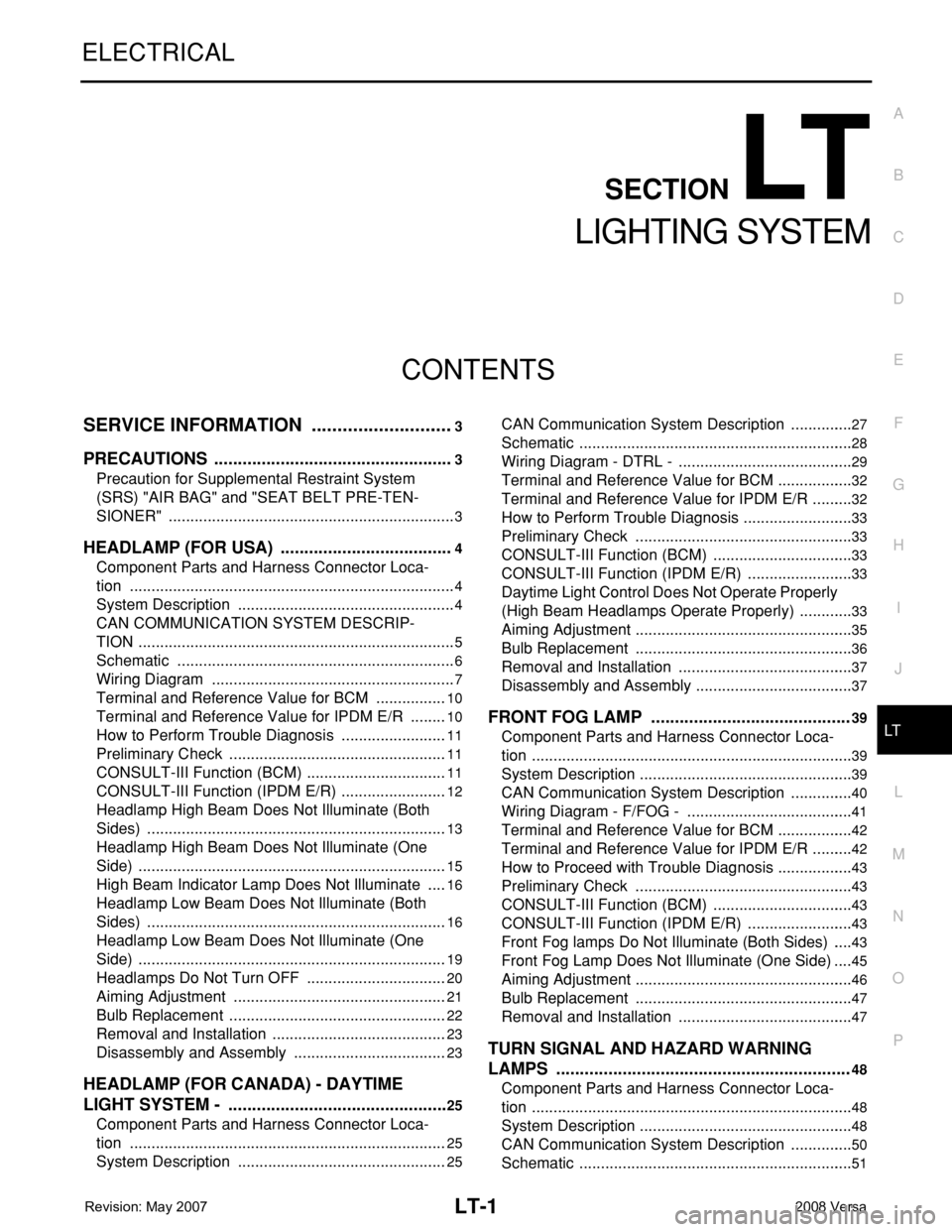
CONTENTS
LIGHTING SYSTEM
SERVICE INFORMATION ............................3
PRECAUTIONS ...................................................3
Precaution for Supplemental Restraint System
(SRS) "AIR BAG" and "SEAT BELT PRE-TEN-
SIONER" ...................................................................
3
HEADLAMP (FOR USA) .....................................4
Component Parts and Harness Connector Loca-
tion ............................................................................
4
System Description ...................................................4
CAN COMMUNICATION SYSTEM DESCRIP-
TION ..........................................................................
5
Schematic .................................................................6
Wiring Diagram .........................................................7
Terminal and Reference Value for BCM .................10
Terminal and Reference Value for IPDM E/R .........10
How to Perform Trouble Diagnosis .........................11
Preliminary Check ...................................................11
CONSULT-III Function (BCM) .................................11
CONSULT-III Function (IPDM E/R) .........................12
Headlamp High Beam Does Not Illuminate (Both
Sides) ......................................................................
13
Headlamp High Beam Does Not Illuminate (One
Side) ........................................................................
15
High Beam Indicator Lamp Does Not Illuminate .....16
Headlamp Low Beam Does Not Illuminate (Both
Sides) ......................................................................
16
Headlamp Low Beam Does Not Illuminate (One
Side) ........................................................................
19
Headlamps Do Not Turn OFF .................................20
Aiming Adjustment ..................................................21
Bulb Replacement ...................................................22
Removal and Installation .........................................23
Disassembly and Assembly ....................................23
HEADLAMP (FOR CANADA) - DAYTIME
LIGHT SYSTEM - ...............................................
25
Component Parts and Harness Connector Loca-
tion ..........................................................................
25
System Description .................................................25
CAN Communication System Description ...............27
Schematic ................................................................28
Wiring Diagram - DTRL - .........................................29
Terminal and Reference Value for BCM ..................32
Terminal and Reference Value for IPDM E/R ..........32
How to Perform Trouble Diagnosis ..........................33
Preliminary Check ...................................................33
CONSULT-III Function (BCM) .................................33
CONSULT-III Function (IPDM E/R) .........................33
Daytime Light Control Does Not Operate Properly
(High Beam Headlamps Operate Properly) .............
33
Aiming Adjustment ...................................................35
Bulb Replacement ...................................................36
Removal and Installation .........................................37
Disassembly and Assembly .....................................37
FRONT FOG LAMP ..........................................39
Component Parts and Harness Connector Loca-
tion ...........................................................................
39
System Description ..................................................39
CAN Communication System Description ...............40
Wiring Diagram - F/FOG - .......................................41
Terminal and Reference Value for BCM ..................42
Terminal and Reference Value for IPDM E/R ..........42
How to Proceed with Trouble Diagnosis ..................43
Preliminary Check ...................................................43
CONSULT-III Function (BCM) .................................43
CONSULT-III Function (IPDM E/R) .........................43
Front Fog lamps Do Not Illuminate (Both Sides) .....43
Front Fog Lamp Does Not Illuminate (One Side) ....45
Aiming Adjustment ...................................................46
Bulb Replacement ...................................................47
Removal and Installation .........................................47
TURN SIGNAL AND HAZARD WARNING
LAMPS ..............................................................
48
Component Parts and Harness Connector Loca-
tion ...........................................................................
48
System Description ..................................................48
CAN Communication System Description ...............50
Schematic ................................................................51
Page 2139 of 2771

LT-2
Wiring Diagram - TURN - ........................................52
Terminal and Reference Value for BCM .................55
How to Proceed with Trouble Diagnosis .................55
Preliminary Check ..................................................56
CONSULT-III Function (BCM) ................................56
Turn Signals Do Not Operate .................................56
Front Turn Signal Lamp Does Not Operate ............56
Rear Turn Signal Lamp Does Not Operate ............57
Hazard Warning Lamp Does Not Operate But
Turn Signal Lamp Operates ...................................
58
Turn Signal Indicator Lamp Does Not Operate ......59
Bulb Replacement for Front Turn Signal Lamp ......59
Bulb Replacement for Rear Turn Signal Lamp .......59
Removal and Installation of Front Turn Signal
Lamp .......................................................................
59
Removal and Installation of Rear Turn Signal
Lamp .......................................................................
59
LIGHTING AND TURN SIGNAL SWITCH .........60
Removal and Installation ........................................60
HAZARD SWITCH .............................................61
Removal and Installation ........................................61
COMBINATION SWITCH ..................................62
Wiring Diagram - COMBSW - .................................62
Combination Switch Reading Function ...................62
Terminal and Reference Value for BCM .................63
CONSULT-III Function (BCM) ................................63
Combination Switch Inspection ..............................63
Removal and Installation ........................................65
STOP LAMP ......................................................66
Wiring Diagram - STOP/L .......................................66
Wiring Diagram - STOP/L .......................................67
Bulb Replacement for High-Mounted Stop Lamp ...67
Bulb Replacement for Rear Combination Lamp for
Stop Lamp ..............................................................
68
Removal and Installation of High-Mounted Stop
Lamp .......................................................................
68
Removal and Installation of Rear Combination
Lamp for Stop Lamp ...............................................
69
BACK-UP LAMP ................................................70
Wiring Diagram - BACK/L - .....................................70
Bulb Replacement ..................................................70
Removal and Installation ........................................71
PARKING, LICENSE PLATE AND TAIL
LAMPS ...............................................................
72
Component Parts and Harness Connector Loca-
tion ..........................................................................
72
System Description .................................................72
CAN Communication System Description ..............73
Schematic ...............................................................74
Wiring Diagram - TAIL/L - .......................................75
Terminal and Reference Value for BCM .................78
Terminal and Reference Value for IPDM E/R .........78
How to Proceed with Trouble Diagnosis .................79
Preliminary Check ...................................................79
CONSULT-III Function (BCM) ................................79
CONSULT-III Function (IPDM E/R) ........................79
Parking, License Plate and Tail Lamps Do Not Il-
luminate ..................................................................
79
Parking, License Plate and Tail Lamps Do Not
Turn OFF (After Approx. 10 Minutes) .....................
82
Bulb Replacement ...................................................82
Removal and Installation .........................................83
REAR COMBINATION LAMP ...........................85
Component .............................................................85
Bulb Replacement ...................................................85
Removal and Installation .........................................86
Disassembly and Assembly ....................................86
INTERIOR LAMP ...............................................87
Map Lamp ...............................................................87
Luggage Compartment Lamp .................................87
INTERIOR ROOM LAMP ...................................89
Component Parts and Harness Connector Loca-
tion ..........................................................................
89
System Description .................................................89
Schematic ...............................................................93
Wiring Diagram - INT/L - .........................................94
Terminal and Reference Value for BCM .................98
How to Proceed with Trouble Diagnosis .................98
Preliminary Check ...................................................99
CONSULT-III Function (BCM) ................................99
Interior Room Lamp Control Does Not Operate
(With Map Lamp) ..................................................
100
Interior Room Lamp Control Does Not Operate
(Without Map Lamp) .............................................
102
Bulb Replacement .................................................103
Removal and Installation .......................................103
ILLUMINATION ................................................105
System Description ...............................................105
CAN Communication System Description ............106
Schematic .............................................................107
Wiring Diagram - ILL - ...........................................108
Bulb Replacement .................................................111
BULB SPECIFICATIONS .................................113
Headlamp ..............................................................113
Exterior Lamp ........................................................113
Interior Lamp/Illumination ......................................113
Page 2142 of 2771

HEADLAMP (FOR USA)
LT-5
< SERVICE INFORMATION >
C
D
E
F
G
H
I
J
L
MA
B
LT
N
O
P
• to BCM terminal 67
• to combination meter terminals 21, 22 and 23
• through grounds M57 and M61, and
• to IPDM E/R terminals 39 and 59
• through grounds E15 and E24.
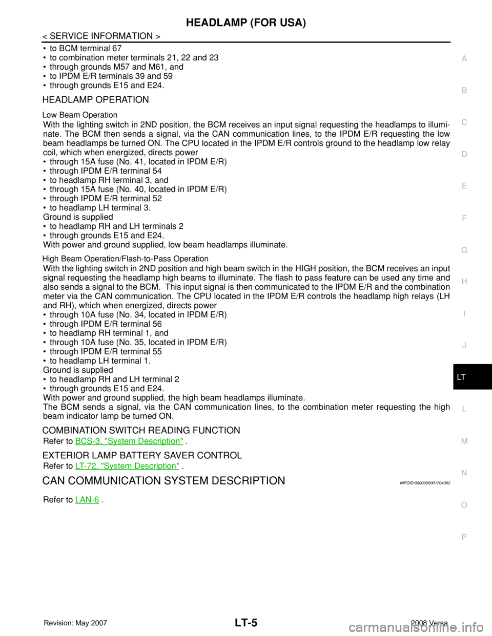
HEADLAMP OPERATION
Low Beam Operation
With the lighting switch in 2ND position, the BCM receives an input signal requesting the headlamps to illumi-
nate. The BCM then sends a signal, via the CAN communication lines, to the IPDM E/R requesting the low
beam headlamps be turned ON. The CPU located in the IPDM E/R controls ground to the headlamp low relay
coil, which when energized, directs power
• through 15A fuse (No. 41, located in IPDM E/R)
• through IPDM E/R terminal 54
• to headlamp RH terminal 3, and
• through 15A fuse (No. 40, located in IPDM E/R)
• through IPDM E/R terminal 52
• to headlamp LH terminal 3.
Ground is supplied
• to headlamp RH and LH terminals 2
• through grounds E15 and E24.
With power and ground supplied, low beam headlamps illuminate.
High Beam Operation/Flash-to-Pass Operation
With the lighting switch in 2ND position and high beam switch in the HIGH position, the BCM receives an input
signal requesting the headlamp high beams to illuminate. The flash to pass feature can be used any time and
also sends a signal to the BCM. This input signal is then communicated to the IPDM E/R and the combination
meter via the CAN communication. The CPU located in the IPDM E/R controls the headlamp high relays (LH
and RH), which when energized, directs power
• through 10A fuse (No. 34, located in IPDM E/R)
• through IPDM E/R terminal 56
• to headlamp RH terminal 1, and
• through 10A fuse (No. 35, located in IPDM E/R)
• through IPDM E/R terminal 55
• to headlamp LH terminal 1.
Ground is supplied
• to headlamp RH and LH terminal 2
• through grounds E15 and E24.
With power and ground supplied, the high beam headlamps illuminate.
The BCM sends a signal, via the CAN communication lines, to the combination meter requesting the high
beam indicator lamp be turned ON.
COMBINATION SWITCH READING FUNCTION
Refer to BCS-3, "System Description" .
EXTERIOR LAMP BATTERY SAVER CONTROL
Refer to LT-72, "System Description" .
CAN COMMUNICATION SYSTEM DESCRIPTIONINFOID:0000000001704362
Refer to LAN-6 .
Page 2163 of 2771
![NISSAN LATIO 2008 Service Repair Manual LT-26
< SERVICE INFORMATION >
HEADLAMP (FOR CANADA) - DAYTIME LIGHT SYSTEM -
• through 10A fuse [No. 3, located in fuse block (J/B)]
• to combination meter terminal 28.
With the ignition switch in NISSAN LATIO 2008 Service Repair Manual LT-26
< SERVICE INFORMATION >
HEADLAMP (FOR CANADA) - DAYTIME LIGHT SYSTEM -
• through 10A fuse [No. 3, located in fuse block (J/B)]
• to combination meter terminal 28.
With the ignition switch in](/manual-img/5/57360/w960_57360-2162.png)
LT-26
< SERVICE INFORMATION >
HEADLAMP (FOR CANADA) - DAYTIME LIGHT SYSTEM -
• through 10A fuse [No. 3, located in fuse block (J/B)]
• to combination meter terminal 28.
With the ignition switch in the ACC or ON position, power is supplied
• through 10A fuse [No. 20, located in fuse block (J/B)]
• to BCM terminal 11.
Ground is supplied
• to BCM terminal 67 and
• to combination meter terminals 21, 22 and 23
• through grounds M57 and M61,
• to IPDM E/R terminals 39 and 59
• through grounds E15 and E24,
HEADLAMP OPERATION
Low Beam Operation
With the lighting switch in 2ND position, the BCM receives an input signal requesting the headlamps to illumi-
nate. This input signal is communicated to the IPDM E/R via the CAN communication lines. The CPU located
in the IPDM E/R controls the headlamp low relay coil, which when energized, directs power
• through 15A fuse (No. 41, located in IPDM E/R)
• through IPDM E/R terminal 54
• to daytime light relay 2 terminals 1 and 5 (energizing the relay),
• through daytime light relay 2 terminal 3
• to front combination lamp RH terminal 3, and
• through 15A fuse (No. 40, located in IPDM E/R)
• through IPDM E/R terminal 52
• to front combination lamp LH terminal 3.
Ground is supplied
• to front combination lamp LH terminal 2
• through grounds E15 and E24,
• to headlamp RH terminal 2 via
• daytime light relay 1 terminals 3 and 4
• through grounds E15 and E24.
With power and ground supplied, low beam headlamps illuminate.
High Beam/Flash-to-Pass Operation
With the lighting switch in 2ND position and high beam switch in the HIGH position, the BCM receives input
signal requesting the headlamp high beams to illuminate. The flash-to-pass feature can be used any time and
also sends a signal to the BCM. This input signal is communicated to the IPDM E/R and the combination
meter via the CAN communication lines. The CPU located in the IPDM E/R controls the headlamp high relay
coil, which when energized, directs power
• through 10A fuse (No. 34, located in IPDM E/R)
• through IPDM E/R terminal 56
• to front combination lamp RH terminal 1, and
• through 10A fuse (No. 35, located in IPDM E/R)
• through IPDM E/R terminal 55
• to front combination lamp LH terminal 1.
Ground is supplied
• to front combination lamp LH terminal 2
• through grounds E15 and E24, and
• to front combination lamp RH terminal 2 via
• daytime light relay 1 terminals 3 and 4
• through grounds E15 and E24.
With power and ground supplied, the high beam headlamps illuminate.
The BCM sends a signal to the combination meter requesting the high beam indicator lamp to turn ON.
Daytime Light System Operation
With the lighting switch in the OFF or 1ST position (parking lamps ON), the BCM receives inputs requesting
the headlights off. If the parking brake is released and the engine is running, the BCM then sends a signal, via
the CAN communication lines, requesting the IPDM E/R to activate the daytime light system. The CPU located
in the IPDM E/R controls the daytime light relay 1 coil, which when energized, directs power
• from daytime light relay 1 terminal 3
• to front combination lamp RH terminal 2,
• through front combination lamp RH high beam terminal 1
Page 2369 of 2771

TROUBLE DIAGNOSIS
MTC-31
< SERVICE INFORMATION >
C
D
E
F
G
H
I
K
L
MA
B
MTC
N
O
P
1. Turn blower control dial clockwise to "1" position. Blower should operate on low speed.
2. Turn blower control dial clockwise to "2" position, and continue checking blower speed until all speeds are
checked.
3. Leave blower on Maximum speed.
If NG, go to trouble diagnosis procedure for MTC-33, "
Front Blower Motor Circuit".
If OK, continue the check.
CHECKING DISCHARGE AIR
1. Turn mode door control dial to each position.
2. Confirm that discharge air comes out according to the air distribution table. Refer to MTC-20, "
Discharge
Air Flow".
If NG, go to trouble diagnosis procedure for MTC-31, "
Mode Door".
If OK, continue the check.
CHECKING RECIRCULATION
1. Set intake door lever to REC position.
2. Operate intake door lever to FRE position.
3. Listen for intake door position change (you should hear blower sound change slightly).
If NG, go to trouble diagnosis procedure for MTC-33, "
Intake Door".
If OK, continue the check.
CHECKING TEMPERATURE DECREASE
1. Turn temperature control dial counterclockwise to full cold position.
2. Check for cold air at discharge air outlets.
If NG, go to trouble diagnosis procedure for MTC-45, "
Insufficient Cooling".
If OK, continue the check.
CHECKING TEMPERATURE INCREASE
1. Turn temperature control dial clockwise to full hot position.
2. Check for hot air at discharge air outlets.
If NG, go to trouble diagnosis procedure for MTC-52, "
Insufficient Heating".
If OK, continue the check.
CHECKING A/C SWITCH (IF EQUIPPED)
1. Turn fan control dial to the desired (1 to 4 speed) position.
2. Press A/C switch.
3. A/C switch indicator will turn ON.
• Confirm that the compressor clutch engages (sound or visual inspection).
If NG, go to trouble diagnosis procedure for MTC-37, "
Magnet Clutch Circuit (If Equipped)".
If OK, continue the check.
CHECKING DEFROST A/C SWITCH (IF EQUIPPED)
1. Turn fan control dial to the desired (1 to 4 speed) position.
2. Turn mode dial to ( ) DEF.
3. Confirm that the compressor clutch engages (sound or visual inspection) and the A/C switch indicator illu-
minates.
If NG, go to trouble diagnosis procedure for MTC-37, "
Magnet Clutch Circuit (If Equipped)".
If all operational checks are OK (symptom cannot be duplicated), go to MTC-22, "
How to Perform Trouble
Diagnosis for Quick and Accurate Repair" and perform tests as outlined. If symptom appears, refer to MTC-22,
"How to Perform Trouble Diagnosis for Quick and Accurate Repair" and perform applicable trouble diagnosis
procedures.
Mode DoorINFOID:0000000001704301
SYMPTOM: Air outlet does not change.
INSPECTION FLOW
Page 2491 of 2771

PG-58
< SERVICE INFORMATION >
HARNESS
Wiring Diagram Codes (Cell Codes)
INFOID:0000000001704709
Use the chart below to find out what each wiring diagram code stands for.
Refer to the wiring diagram code in the alphabetical index to find the location (page number) of each wiring
diagram.
D3 D404 W/3 : Rear wiper motor
D4 D405 W/4 : Back door lock assembly
D4 D406 W/2 : Back door request switch
E2 D407 W/2 : High mounted stop lamp
D4 D408 BR/2 : Back door opener switch
E4 D409 B/1 : Condenser-1
C2 D410 — : Body ground
E3 D411 B/1 : Condenser-1
E1 D412 B/1 : Rear window defogger (+)
C2 D413 B/1 : Rear window defogger (-)
F3 D414 — : Body ground
Code Section Wiring Diagram Name
ABS BRC Anti-lock Brake System
A/C,M MTC Manual Air Conditioner
APPS1 EC Accelerator Pedal Position Sensor
A/F EC Air Fuel Ratio Sensor 1
A/FH EC Air Fuel Ratio Sensor 1 Heater
APPS2 EC Accelerator Pedal Position Sensor
APPS3 EC Accelerator Pedal Position Sensor
ASC/BS EC ASCD Brake Switch
ASC/SW EC ASCD Steering Switch
ASCBOF EC ASCD Brake Switch
ASCIND EC ASCD Indicator
AT/IND DI A/T Indicator Lamp
AUDIO AV Audio
BACK/L LT Back-up Lamp
BA/FTS AT A/T Fluid Temperature Sensor and TCM Power Supply
B/DOOR BL Back Door Opener
BRK/SW EC Brake Switch
CAN AT CAN Communication Line
CAN CVT CAN Communication Line
CAN EC CAN Communication Line
CAN LAN CAN System
CHARGE SC Charging System
CHIME DI Warning Chime
COOL/F EC Cooling Fan Control
COMBSW LT Combination Switch
CVTIND DI CVT Indicator Lamp
D/LOCK BL Power Door Lock
DEF GW Rear Window Defogger
DTRL LT Headlamp - With Daytime Light System
ECTS EC Engine Coolant Temperature Sensor
ENGSS AT Engine Speed Signal
EPS STC Electronic Controlled Power Steering
ETC1 EC Electric Throttle Control Function
Page 2661 of 2771

TROUBLE DIAGNOSIS
SRS-27
< SYMPTOM DIAGNOSIS >
C
D
E
F
G
I
J
K
L
MA
B
SRS
N
O
P
NOTE:
Follow the procedures in numerical order when performing repairs. Confirm whether the repair has been suc-
cessful using air bag warning lamp or CONSULT-III after each repair. If malfunction is still observed, proceed
to the next step. When malfunction has been eliminated, further repair work is not required.
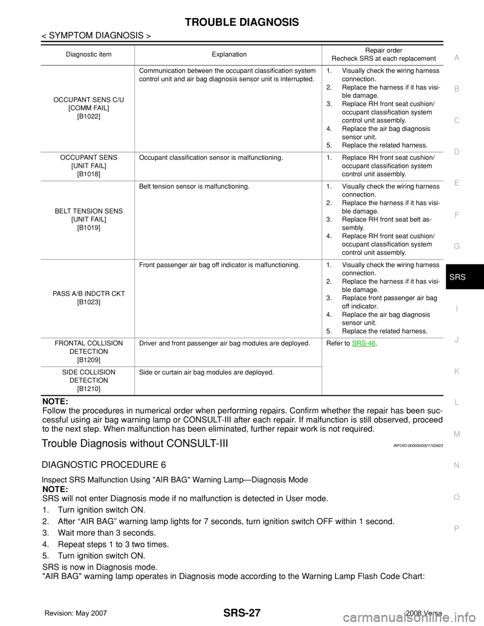
Trouble Diagnosis without CONSULT-IIIINFOID:0000000001703923
DIAGNOSTIC PROCEDURE 6
Inspect SRS Malfunction Using "AIR BAG" Warning Lamp—Diagnosis Mode
NOTE:
SRS will not enter Diagnosis mode if no malfunction is detected in User mode.
1. Turn ignition switch ON.
2. After “AIR BAG” warning lamp lights for 7 seconds, turn ignition switch OFF within 1 second.
3. Wait more than 3 seconds.
4. Repeat steps 1 to 3 two times.
5. Turn ignition switch ON.
SRS is now in Diagnosis mode.
"AIR BAG" warning lamp operates in Diagnosis mode according to the Warning Lamp Flash Code Chart:
OCCUPANT SENS C/U
[COMM FAIL]
[B1022]Communication between the occupant classification system
control unit and air bag diagnosis sensor unit is interrupted.1. Visually check the wiring harness
connection.
2. Replace the harness if it has visi-
ble damage.
3. Replace RH front seat cushion/
occupant classification system
control unit assembly.
4. Replace the air bag diagnosis
sensor unit.
5. Replace the related harness.
OCCUPANT SENS
[UNIT FAIL]
[B1018]Occupant classification sensor is malfunctioning. 1. Replace RH front seat cushion/
occupant classification system
control unit assembly.
BELT TENSION SENS
[UNIT FAIL]
[B1019]Belt tension sensor is malfunctioning. 1. Visually check the wiring harness
connection.
2. Replace the harness if it has visi-
ble damage.
3. Replace RH front seat belt as-
sembly.
4. Replace RH front seat cushion/
occupant classification system
control unit assembly.
PASS A/B INDCTR CKT
[B1023]Front passenger air bag off indicator is malfunctioning. 1. Visually check the wiring harness
connection.
2. Replace the harness if it has visi-
ble damage.
3. Replace front passenger air bag
off indicator.
4. Replace the air bag diagnosis
sensor unit.
5. Replace the related harness.
FRONTAL COLLISION
DETECTION
[B1209]Driver and front passenger air bag modules are deployed. Refer to SRS-46
.
SIDE COLLISION
DETECTION
[B1210]Side or curtain air bag modules are deployed. Diagnostic item ExplanationRepair order
Recheck SRS at each replacement