2008 NISSAN LATIO Indicator light
[x] Cancel search: Indicator lightPage 1120 of 2771

EC-46
< SERVICE INFORMATION >
ON BOARD DIAGNOSTIC (OBD) SYSTEM
ON BOARD DIAGNOSTIC (OBD) SYSTEM
IntroductionINFOID:0000000001702573
The ECM has an on board diagnostic system, which detects malfunctions related to engine sensors or actua-
tors. The ECM also records various emission-related diagnostic information including:
The above information can be checked using procedures listed in the table below.
×: Applicable —: Not applicable
*: When DTC and 1st trip DTC simultaneously appear on the display, they cannot be clearly distinguished from each other.
The malfunction indicator lamp (MIL) on the instrument panel lights up when the same malfunction is detected
in two consecutive trips (Two trip detection logic), or when the ECM enters fail-safe mode.
(Refer to EC-87, "
Fail-Safe Chart".)
Two Trip Detection LogicINFOID:0000000001702574
When a malfunction is detected for the first time, 1st trip DTC and 1st trip Freeze Frame data are stored in the
ECM memory. The MIL will not light up at this stage. <1st trip>
If the same malfunction is detected again during the next drive, the DTC and Freeze Frame data are stored in
the ECM memory, and the MIL lights up. The MIL lights up at the same time when the DTC is stored. <2nd
trip> The “trip” in the “Two Trip Detection Logic” means a driving mode in which self-diagnosis is performed
during vehicle operation. Specific on board diagnostic items will cause the ECM to light up or blink the MIL,
and store DTC and Freeze Frame data, even in the 1st trip, as shown below.
×: Applicable —: Not applicable
When there is an open circuit on MIL circuit, the ECM cannot warn the driver by MIL lighting up when there is
malfunction on engine control system.
Emission-related diagnostic information Diagnostic service
Diagnostic Trouble Code (DTC) Service $03 of SAE J1979
Freeze Frame data Service $02 of SAE J1979
System Readiness Test (SRT) code Service $01 of SAE J1979
1st Trip Diagnostic Trouble Code (1st Trip DTC) Service $07 of SAE J1979
1st Trip Freeze Frame data
Test values and Test limits Service $06 of SAE J1979
Calibration ID Service $09 of SAE J1979
DTC 1st trip DTCFreeze Frame
data1st trip Freeze
Frame dataSRT code SRT status Test value
CONSULT-II××××××—
GST×× ×—×××
ECM××*———×—
ItemsMIL DTC 1st trip DTC
1st trip 2nd trip
1st trip
displaying2nd trip
displaying1st trip
displaying2nd trip
display-
ing BlinkingLighting
upBlinkingLighting
up
Misfire (Possible three way catalyst
damage) — DTC: P0300 - P0304 is
being detected×———— —×—
Misfire (Possible three way catalyst
damage) — DTC: P0300 - P0304 is
being detected——×——×——
One trip detection diagnoses
(Refer to EC-47, "
Emission-related
Diagnostic Information".)—×——×———
Except above — — —×—××—
Page 1134 of 2771
EC-60
< SERVICE INFORMATION >
ON BOARD DIAGNOSTIC (OBD) SYSTEM
2. Perform AT-36, "OBD-II Diagnostic Trouble Code (DTC)" or "How to Erase DTC". (The DTC in the TCM
will be erased.)
3. Change the diagnostic test mode from Mode II to Mode I by depressing the accelerator pedal.
Refer to EC-60, "
Malfunction Indicator Lamp (MIL)".
•If the battery is disconnected, the emission-related diagnostic information will be lost within 24
hours.
•The following data are cleared when the ECM memory is erased.
- Diagnostic trouble codes
- 1st trip diagnostic trouble codes
- Freeze frame data
- 1st trip freeze frame data
- System readiness test (SRT) codes
- Test values
Actual work procedures are explained using a DTC as an example. Be careful so that not only the DTC, but all
of the data listed above, are cleared from the ECM memory during work procedures.
Malfunction Indicator Lamp (MIL)INFOID:0000000001702576
DESCRIPTION
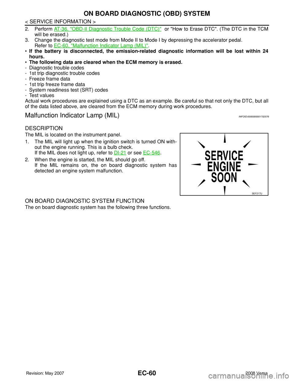
The MIL is located on the instrument panel.
1. The MIL will light up when the ignition switch is turned ON with-
out the engine running. This is a bulb check.
If the MIL does not light up, refer to DI-21
or see EC-546.
2. When the engine is started, the MIL should go off.
If the MIL remains on, the on board diagnostic system has
detected an engine system malfunction.
ON BOARD DIAGNOSTIC SYSTEM FUNCTION
The on board diagnostic system has the following three functions.
SEF217U
Page 1145 of 2771
BASIC SERVICE PROCEDURE
EC-71
< SERVICE INFORMATION >
C
D
E
F
G
H
I
J
K
L
MA
EC
N
P O
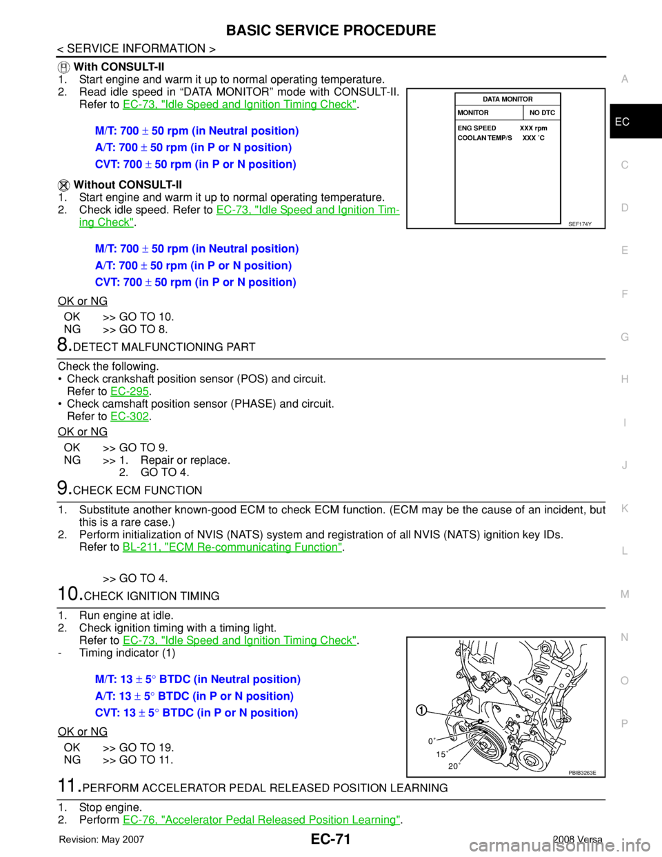
With CONSULT-II
1. Start engine and warm it up to normal operating temperature.
2. Read idle speed in “DATA MONITOR” mode with CONSULT-II.
Refer to EC-73, "
Idle Speed and Ignition Timing Check".
Without CONSULT-II
1. Start engine and warm it up to normal operating temperature.
2. Check idle speed. Refer to EC-73, "
Idle Speed and Ignition Tim-
ing Check".
OK or NG
OK >> GO TO 10.
NG >> GO TO 8.
8.DETECT MALFUNCTIONING PART
Check the following.
• Check crankshaft position sensor (POS) and circuit.
Refer to EC-295
.
• Check camshaft position sensor (PHASE) and circuit.
Refer to EC-302
.
OK or NG
OK >> GO TO 9.
NG >> 1. Repair or replace.
2. GO TO 4.
9.CHECK ECM FUNCTION
1. Substitute another known-good ECM to check ECM function. (ECM may be the cause of an incident, but
this is a rare case.)
2. Perform initialization of NVIS (NATS) system and registration of all NVIS (NATS) ignition key IDs.
Refer to BL-211, "
ECM Re-communicating Function".
>> GO TO 4.
10.CHECK IGNITION TIMING
1. Run engine at idle.
2. Check ignition timing with a timing light.
Refer to EC-73, "
Idle Speed and Ignition Timing Check".
- Timing indicator (1)
OK or NG
OK >> GO TO 19.
NG >> GO TO 11.
11 .PERFORM ACCELERATOR PEDAL RELEASED POSITION LEARNING
1. Stop engine.
2. Perform EC-76, "
Accelerator Pedal Released Position Learning". M/T: 700 ± 50 rpm (in Neutral position)
A/T: 700 ± 50 rpm (in P or N position)
CVT: 700 ± 50 rpm (in P or N position)
M/T: 700 ± 50 rpm (in Neutral position)
A/T: 700 ± 50 rpm (in P or N position)
CVT: 700 ± 50 rpm (in P or N position)
SEF174Y
M/T: 13 ± 5° BTDC (in Neutral position)
A/T: 13 ± 5° BTDC (in P or N position)
CVT: 13 ± 5° BTDC (in P or N position)
PBIB3263E
Page 1146 of 2771
EC-72
< SERVICE INFORMATION >
BASIC SERVICE PROCEDURE
>> GO TO 12.
12.PERFORM THROTTLE VALVE CLOSED POSITION LEARNING
Perform EC-76, "
Throttle Valve Closed Position Learning".
>> GO TO 13.
13.PERFORM IDLE AIR VOLUME LEARNING
Refer to EC-76, "
Idle Air Volume Learning".
Is Idle Air Volume Learning carried out successfully?
Ye s o r N o
Yes >> GO TO 14.
No >> 1. Follow the instruction of Idle Air Volume Learning.
2. GO TO 4.
14.CHECK TARGET IDLE SPEED AGAIN
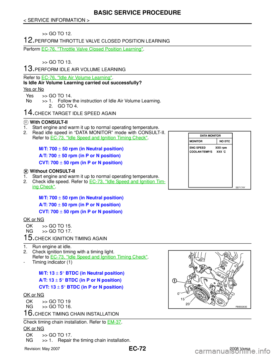
With CONSULT-II
1. Start engine and warm it up to normal operating temperature.
2. Read idle speed in “DATA MONITOR” mode with CONSULT-II.
Refer to EC-73, "
Idle Speed and Ignition Timing Check".
Without CONSULT-II
1. Start engine and warm it up to normal operating temperature.
2. Check idle speed. Refer to EC-73, "
Idle Speed and Ignition Tim-
ing Check".
OK or NG
OK >> GO TO 15.
NG >> GO TO 17.
15.CHECK IGNITION TIMING AGAIN
1. Run engine at idle.
2. Check ignition timing with a timing light.
Refer to EC-73, "
Idle Speed and Ignition Timing Check".
- Timing indicator (1)
OK or NG
OK >> GO TO 19
NG >> GO TO 16.
16.CHECK TIMING CHAIN INSTALLATION
Check timing chain installation. Refer to EM-37
.
OK or NG
OK >> GO TO 17.
NG >> 1. Repair the timing chain installation.M/T: 700 ± 50 rpm (in Neutral position)
A/T: 700 ± 50 rpm (in P or N position)
CVT: 700 ± 50 rpm (in P or N position)
M/T: 700 ± 50 rpm (in Neutral position)
A/T: 700 ± 50 rpm (in P or N position)
CVT: 700 ± 50 rpm (in P or N position)
SEF174Y
M/T: 13 ± 5° BTDC (in Neutral position)
A/T: 13 ± 5° BTDC (in P or N position)
CVT: 13 ± 5° BTDC (in P or N position)
PBIB3263E
Page 1148 of 2771
EC-74
< SERVICE INFORMATION >
BASIC SERVICE PROCEDURE
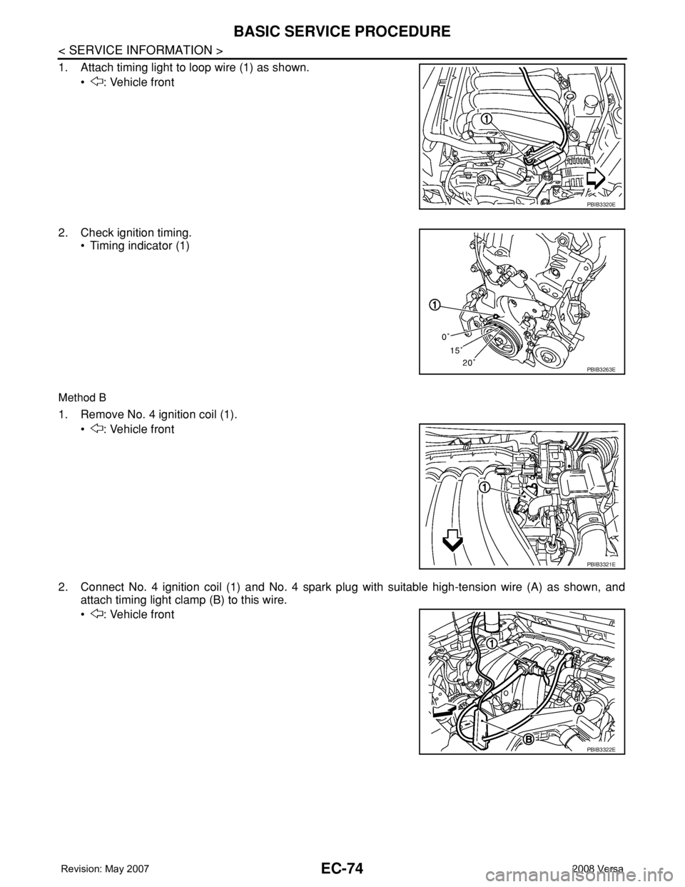
1. Attach timing light to loop wire (1) as shown.
• : Vehicle front
2. Check ignition timing.
• Timing indicator (1)
Method B
1. Remove No. 4 ignition coil (1).
• : Vehicle front
2. Connect No. 4 ignition coil (1) and No. 4 spark plug with suitable high-tension wire (A) as shown, and
attach timing light clamp (B) to this wire.
• : Vehicle front
PBIB3320E
PBIB3263E
PBIB3321E
PBIB3322E
Page 1513 of 2771
DTC P1572 ASCD BRAKE SWITCH
EC-439
< SERVICE INFORMATION >
C
D
E
F
G
H
I
J
K
L
MA
EC
N
P O
DTC Confirmation ProcedureINFOID:0000000001702961
CAUTION:
Always drive vehicle at a safe speed.
NOTE:
• If DTC Confirmation Procedure has been previously conducted, always turn ignition switch OFF and wait at
least 10 seconds before conducting the next test.
• Procedure for malfunction B is not described here. It takes extremely long time to complete procedure for
malfunction B. By performing procedure for malfunction A, the incident that causes malfunction B can be
detected.
TESTING CONDITION:
Steps 4 and 5 may be conducted with the drive wheels lifted in the shop or by driving the vehicle. If a
road test is expected to be easier, it is unnecessary to lift the vehicle.
WITH CONSULT-II
1. Start engine.
2. Select “DATA MONITOR” mode with CONSULT-II.
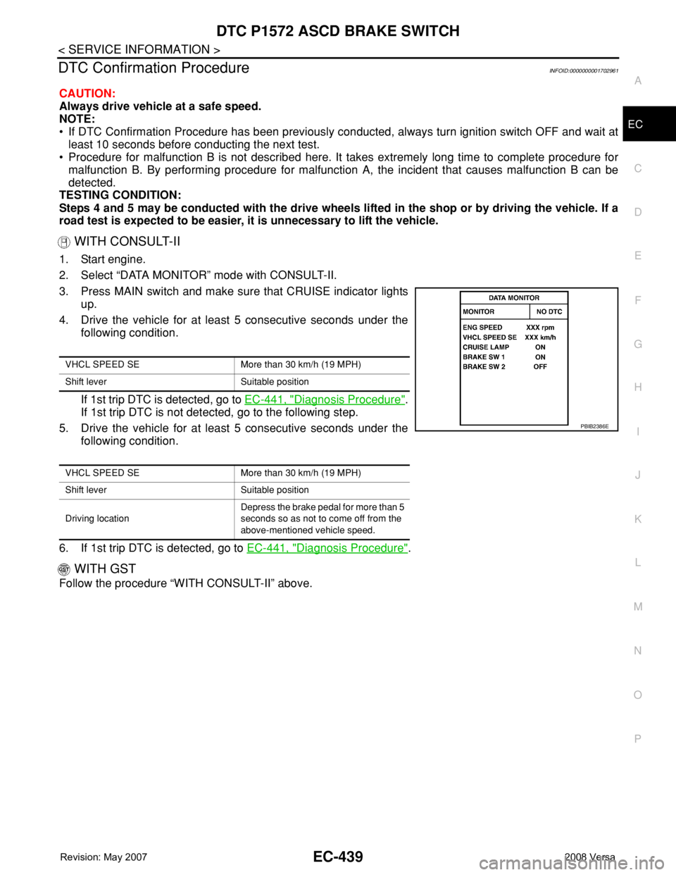
3. Press MAIN switch and make sure that CRUISE indicator lights
up.
4. Drive the vehicle for at least 5 consecutive seconds under the
following condition.
If 1st trip DTC is detected, go to EC-441, "
Diagnosis Procedure".
If 1st trip DTC is not detected, go to the following step.
5. Drive the vehicle for at least 5 consecutive seconds under the
following condition.
6. If 1st trip DTC is detected, go to EC-441, "
Diagnosis Procedure".
WITH GST
Follow the procedure “WITH CONSULT-II” above.
VHCL SPEED SE More than 30 km/h (19 MPH)
Shift lever Suitable position
VHCL SPEED SE More than 30 km/h (19 MPH)
Shift lever Suitable position
Driving locationDepress the brake pedal for more than 5
seconds so as not to come off from the
above-mentioned vehicle speed.
PBIB2386E
Page 1899 of 2771

GI-48
< SERVICE INFORMATION >
TERMINOLOGY
Exhaust gas recirculation control-BPT
valveEGRC-BPT valve BPT valve
Exhaust gas recirculation control-solenoid
valveEGRC-solenoid valve EGR control solenoid valve
Exhaust gas recirculation temperature sen-
sor
EGRT sensor Exhaust gas temperature sensor
EGR temperature sensor
Flash electrically erasable programmable
read only memoryFEEPROM ***
Flash erasable programmable read only
memoryFEPROM ***
Flexible fuel sensor FFS ***
Flexible fuel system FF system ***
Fuel pressure regulator *** Pressure regulator
Fuel pressure regulator control solenoid
valve*** PRVR control solenoid valve
Fuel trim FT ***
Heated Oxygen sensor HO2S Exhaust gas sensor
Idle air control system IAC system Idle speed control
Idle air control valve-air regulator IACV-air regulator Air regulator
Idle air control valve-auxiliary air control
valveIACV-AAC valve Auxiliary air control (AAC) valve
Idle air control valve-FICD solenoid valve IACV-FICD solenoid valve FICD solenoid valve
Idle air control valve-idle up control sole-
noid valveIACV-idle up control solenoid valve Idle up control solenoid valve
Idle speed control-FI pot ISC-FI pot FI pot
Idle speed control system ISC system ***
Ignition control IC ***
Ignition control module ICM ***
Indirect fuel injection system IFI system ***
Intake air IA Air
Intake air temperature sensor IAT sensor Air temperature sensor
Knock *** Detonation
Knock sensor KS Detonation sensor
Malfunction indicator lamp MIL Check engine light
Manifold absolute pressure MAP ***
Manifold absolute pressure sensor MAPS ***
Manifold differential pressure MDP ***
Manifold differential pressure sensor MDPS ***
Manifold surface temperature MST ***
Manifold surface temperature sensor MSTS ***
Manifold vacuum zone MVZ ***
Manifold vacuum zone sensor MVZS ***
Mass air flow sensor MAFS Air flow meter
Mixture control solenoid valve MC solenoid valve Air-fuel ratio control solenoid valve
Multiport fuel injection System MFI system Fuel injection controlNEW TERMNEW ACRONYM /
ABBREVIATIONOLD TERM
Page 2015 of 2771
![NISSAN LATIO 2008 Service Repair Manual LAN-24
< FUNCTION DIAGNOSIS >[CAN]
CAN COMMUNICATION SYSTEM
Engine coolant temperature signal T R
Engine speed signal T R R
Engine status signal T R
Fuel consumption monitor signal T R
Malfunction ind NISSAN LATIO 2008 Service Repair Manual LAN-24
< FUNCTION DIAGNOSIS >[CAN]
CAN COMMUNICATION SYSTEM
Engine coolant temperature signal T R
Engine speed signal T R R
Engine status signal T R
Fuel consumption monitor signal T R
Malfunction ind](/manual-img/5/57360/w960_57360-2014.png)
LAN-24
< FUNCTION DIAGNOSIS >[CAN]
CAN COMMUNICATION SYSTEM
Engine coolant temperature signal T R
Engine speed signal T R R
Engine status signal T R
Fuel consumption monitor signal T R
Malfunction indicator lamp signal T R
Wide open throttle position signal T R R
A/C switch signal R T
Blower fan motor switch signal R T
Buzzer output signalTR
TR
Day time running light request signal
*3TR R
Door lock/unlock status signal T R
Door switch signal T R R R
Front wiper request signal T R
High beam request signal T R R
Horn chirp signal T R
Ignition switch signal T R
Low beam request signal T R
Position lights request signal T R R
Rear window defogger switch signal T R
Sleep/wake up signalRT
TRR R
Theft warning horn request signal T R
Tire pressure signal
*4TR
Trunk open/close status signal T R
Turn indicator signal T R
EPS operation signal R T
EPS warning lamp signal T R
Door lock/unlock/trunk open request signal R T
Hazard request signal R T
Ignition knob switch signal R T
KEY warning lamp signal T R
LOCK warning lamp signal T R
Panic alarm request signal R T
Fuel level sensor signal R T
Overdrive control switch signal T R R
P/N range signal T R
Stop lamp switch signal T R R
Vehicle speed signalRRR T
RRRT R
R
*5R*5T*5
ABS warning lamp signal R TSignal name/Connecting unit
ECM
BCM
EPS
I-KEY
M&A
ABS
TCM
*1
TCM
*2
IPDM-E