2008 NISSAN LATIO ECO mode
[x] Cancel search: ECO modePage 156 of 2771
AT-144
< SERVICE INFORMATION >
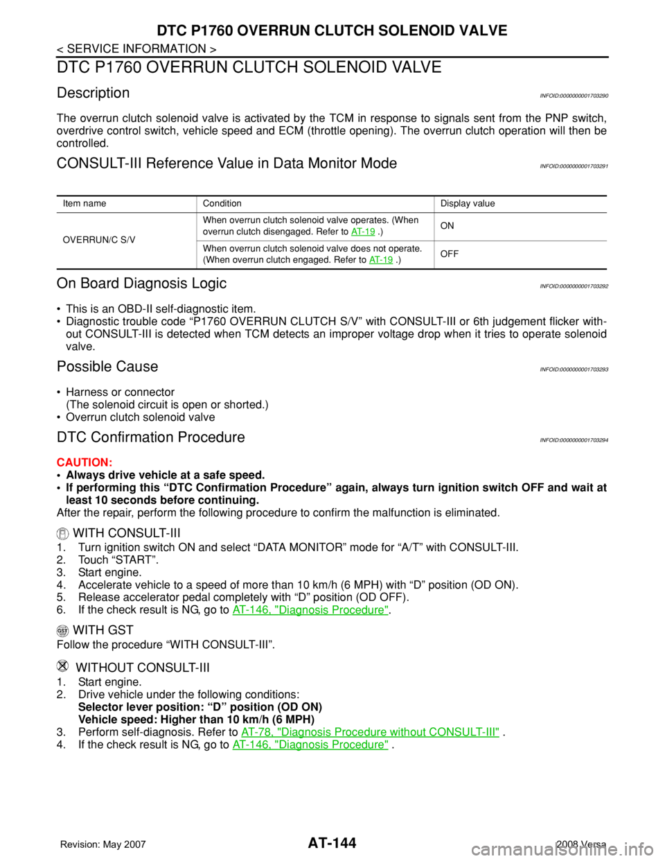
DTC P1760 OVERRUN CLUTCH SOLENOID VALVE
DTC P1760 OVERRUN CLUTCH SOLENOID VALVE
DescriptionINFOID:0000000001703290
The overrun clutch solenoid valve is activated by the TCM in response to signals sent from the PNP switch,
overdrive control switch, vehicle speed and ECM (throttle opening). The overrun clutch operation will then be
controlled.
CONSULT-III Reference Value in Data Monitor ModeINFOID:0000000001703291
On Board Diagnosis LogicINFOID:0000000001703292
• This is an OBD-II self-diagnostic item.
• Diagnostic trouble code “P1760 OVERRUN CLUTCH S/V” with CONSULT-III or 6th judgement flicker with-
out CONSULT-III is detected when TCM detects an improper voltage drop when it tries to operate solenoid
valve.
Possible CauseINFOID:0000000001703293
• Harness or connector
(The solenoid circuit is open or shorted.)
• Overrun clutch solenoid valve
DTC Confirmation ProcedureINFOID:0000000001703294
CAUTION:
• Always drive vehicle at a safe speed.
• If performing this “DTC Confirmation Procedure” again, always turn ignition switch OFF and wait at
least 10 seconds before continuing.
After the repair, perform the following procedure to confirm the malfunction is eliminated.
WITH CONSULT-III
1. Turn ignition switch ON and select “DATA MONITOR” mode for “A/T” with CONSULT-III.
2. Touch “START”.
3. Start engine.
4. Accelerate vehicle to a speed of more than 10 km/h (6 MPH) with “D” position (OD ON).
5. Release accelerator pedal completely with “D” position (OD OFF).
6. If the check result is NG, go to AT-146, "
Diagnosis Procedure".
WITH GST
Follow the procedure “WITH CONSULT-III”.
WITHOUT CONSULT-III
1. Start engine.
2. Drive vehicle under the following conditions:
Selector lever position: “D” position (OD ON)
Vehicle speed: Higher than 10 km/h (6 MPH)
3. Perform self-diagnosis. Refer to AT-78, "
Diagnosis Procedure without CONSULT-III" .
4. If the check result is NG, go to AT-146, "
Diagnosis Procedure" .
Item name Condition Display value
OVERRUN/C S/VWhen overrun clutch solenoid valve operates. (When
overrun clutch disengaged. Refer to AT- 1 9
.)ON
When overrun clutch solenoid valve does not operate.
(When overrun clutch engaged. Refer to AT- 1 9
.)OFF
Page 161 of 2771
DTC VEHICLE SPEED SENSOR MTR
AT-149
< SERVICE INFORMATION >
D
E
F
G
H
I
J
K
L
MA
B
AT
N
O
P
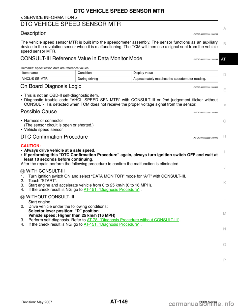
DTC VEHICLE SPEED SENSOR MTR
DescriptionINFOID:0000000001703298
The vehicle speed sensor·MTR is built into the speedometer assembly. The sensor functions as an auxiliary
device to the revolution sensor when it is malfunctioning. The TCM will then use a signal sent from the vehicle
speed sensor·MTR.
CONSULT-III Reference Value in Data Monitor ModeINFOID:0000000001703299
Remarks: Specification data are reference values.
On Board Diagnosis LogicINFOID:0000000001703300
• This is not an OBD-II self-diagnostic item.
• Diagnostic trouble code “VHCL SPEED SEN-MTR” with CONSULT-III or 2nd judgement flicker without
CONSULT-III is detected when TCM does not receive the proper voltage signal from the sensor.
Possible CauseINFOID:0000000001703301
• Harness or connector
(The sensor circuit is open or shorted.)
• Vehicle speed sensor
DTC Confirmation ProcedureINFOID:0000000001703302
CAUTION:
• Always drive vehicle at a safe speed.
• If performing this “DTC Confirmation Procedure” again, always turn ignition switch OFF and wait at
least 10 seconds before continuing.
After the repair, perform the following procedure to confirm the malfunction is eliminated.
WITH CONSULT-III
1. Turn ignition switch ON and select “DATA MONITOR” mode for “A/T” with CONSULT-III.
2. Touch “START”.
3. Start engine and accelerate vehicle from 0 to 25 km/h (0 to 16 MPH).
4. If the check result is NG, go to AT-151, "
Diagnosis Procedure" .
WITHOUT CONSULT-III
1. Start engine.
2. Drive vehicle under the following conditions:
Selector lever position: “D” position
Vehicle speed: Higher than 25 km/h (16 MPH)
3. Perform self-diagnosis. Refer to AT-78, "
Diagnosis Procedure without CONSULT-III" .
4. If the check result is NG, go to AT-151, "
Diagnosis Procedure" .
Item name Condition Display value
VHCL/S SE-MTR During driving Approximately matches the speedometer reading.
Page 164 of 2771
AT-152
< SERVICE INFORMATION >
DTC BATT/FLUID TEMP SEN (A/T FLUID TEMP SENSOR CIRCUIT AND TCM
POWER SOURCE)
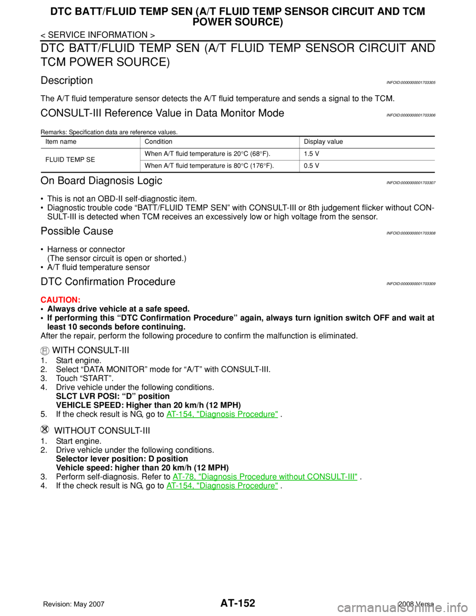
DTC BATT/FLUID TEMP SEN (A/T FLUID TEMP SENSOR CIRCUIT AND
TCM POWER SOURCE)
DescriptionINFOID:0000000001703305
The A/T fluid temperature sensor detects the A/T fluid temperature and sends a signal to the TCM.
CONSULT-III Reference Value in Data Monitor ModeINFOID:0000000001703306
Remarks: Specification data are reference values.
On Board Diagnosis LogicINFOID:0000000001703307
• This is not an OBD-II self-diagnostic item.
• Diagnostic trouble code “BATT/FLUID TEMP SEN” with CONSULT-III or 8th judgement flicker without CON-
SULT-III is detected when TCM receives an excessively low or high voltage from the sensor.
Possible CauseINFOID:0000000001703308
• Harness or connector
(The sensor circuit is open or shorted.)
• A/T fluid temperature sensor
DTC Confirmation ProcedureINFOID:0000000001703309
CAUTION:
• Always drive vehicle at a safe speed.
• If performing this “DTC Confirmation Procedure” again, always turn ignition switch OFF and wait at
least 10 seconds before continuing.
After the repair, perform the following procedure to confirm the malfunction is eliminated.
WITH CONSULT-III
1. Start engine.
2. Select “DATA MONITOR” mode for “A/T” with CONSULT-III.
3. Touch “START”.
4. Drive vehicle under the following conditions.
SLCT LVR POSI: “D” position
VEHICLE SPEED: Higher than 20 km/h (12 MPH)
5. If the check result is NG, go to AT-154, "
Diagnosis Procedure" .
WITHOUT CONSULT-III
1. Start engine.
2. Drive vehicle under the following conditions.
Selector lever position: D position
Vehicle speed: higher than 20 km/h (12 MPH)
3. Perform self-diagnosis. Refer to AT-78, "
Diagnosis Procedure without CONSULT-III" .
4. If the check result is NG, go to AT-154, "
Diagnosis Procedure" .
Item name Condition Display value
FLUID TEMP SEWhen A/T fluid temperature is 20°C (68°F). 1.5 V
When A/T fluid temperature is 80°C (176°F). 0.5 V
Page 170 of 2771
AT-158
< SERVICE INFORMATION >
DTC TURBINE REVOLUTION SENSOR
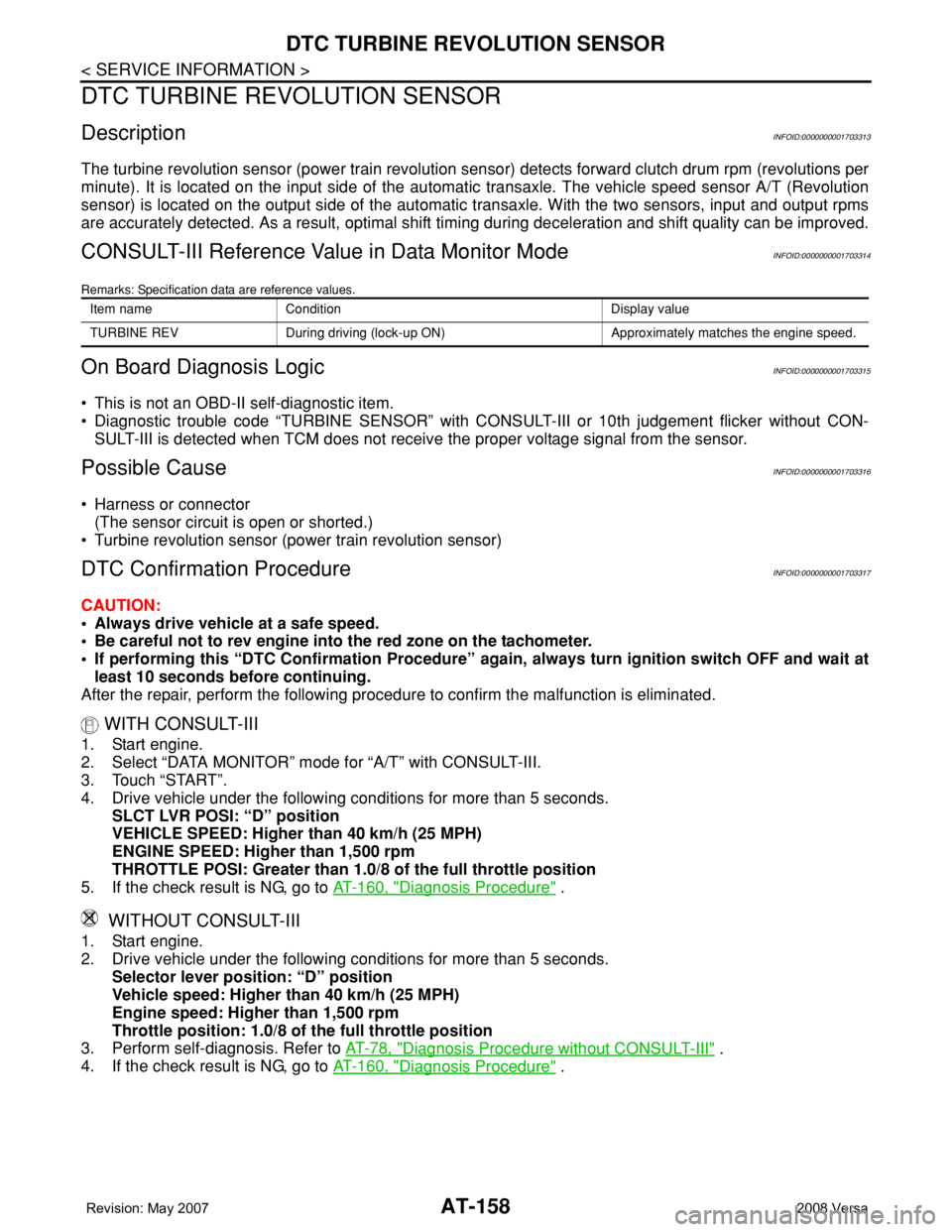
DTC TURBINE REVOLUTION SENSOR
DescriptionINFOID:0000000001703313
The turbine revolution sensor (power train revolution sensor) detects forward clutch drum rpm (revolutions per
minute). It is located on the input side of the automatic transaxle. The vehicle speed sensor A/T (Revolution
sensor) is located on the output side of the automatic transaxle. With the two sensors, input and output rpms
are accurately detected. As a result, optimal shift timing during deceleration and shift quality can be improved.
CONSULT-III Reference Value in Data Monitor ModeINFOID:0000000001703314
Remarks: Specification data are reference values.
On Board Diagnosis LogicINFOID:0000000001703315
• This is not an OBD-II self-diagnostic item.
• Diagnostic trouble code “TURBINE SENSOR” with CONSULT-III or 10th judgement flicker without CON-
SULT-III is detected when TCM does not receive the proper voltage signal from the sensor.
Possible CauseINFOID:0000000001703316
• Harness or connector
(The sensor circuit is open or shorted.)
• Turbine revolution sensor (power train revolution sensor)
DTC Confirmation ProcedureINFOID:0000000001703317
CAUTION:
• Always drive vehicle at a safe speed.
• Be careful not to rev engine into the red zone on the tachometer.
• If performing this “DTC Confirmation Procedure” again, always turn ignition switch OFF and wait at
least 10 seconds before continuing.
After the repair, perform the following procedure to confirm the malfunction is eliminated.
WITH CONSULT-III
1. Start engine.
2. Select “DATA MONITOR” mode for “A/T” with CONSULT-III.
3. Touch “START”.
4. Drive vehicle under the following conditions for more than 5 seconds.
SLCT LVR POSI: “D” position
VEHICLE SPEED: Higher than 40 km/h (25 MPH)
ENGINE SPEED: Higher than 1,500 rpm
THROTTLE POSI: Greater than 1.0/8 of the full throttle position
5. If the check result is NG, go to AT-160, "
Diagnosis Procedure" .
WITHOUT CONSULT-III
1. Start engine.
2. Drive vehicle under the following conditions for more than 5 seconds.
Selector lever position: “D” position
Vehicle speed: Higher than 40 km/h (25 MPH)
Engine speed: Higher than 1,500 rpm
Throttle position: 1.0/8 of the full throttle position
3. Perform self-diagnosis. Refer to AT-78, "
Diagnosis Procedure without CONSULT-III" .
4. If the check result is NG, go to AT-160, "
Diagnosis Procedure" .
Item name Condition Display value
TURBINE REV During driving (lock-up ON) Approximately matches the engine speed.
Page 175 of 2771
CONTROL UNIT (RAM), CONTROL UNIT (ROM)
AT-163
< SERVICE INFORMATION >
D
E
F
G
H
I
J
K
L
MA
B
AT
N
O
P
CONTROL UNIT (RAM), CONTROL UNIT (ROM)
DescriptionINFOID:0000000001703320
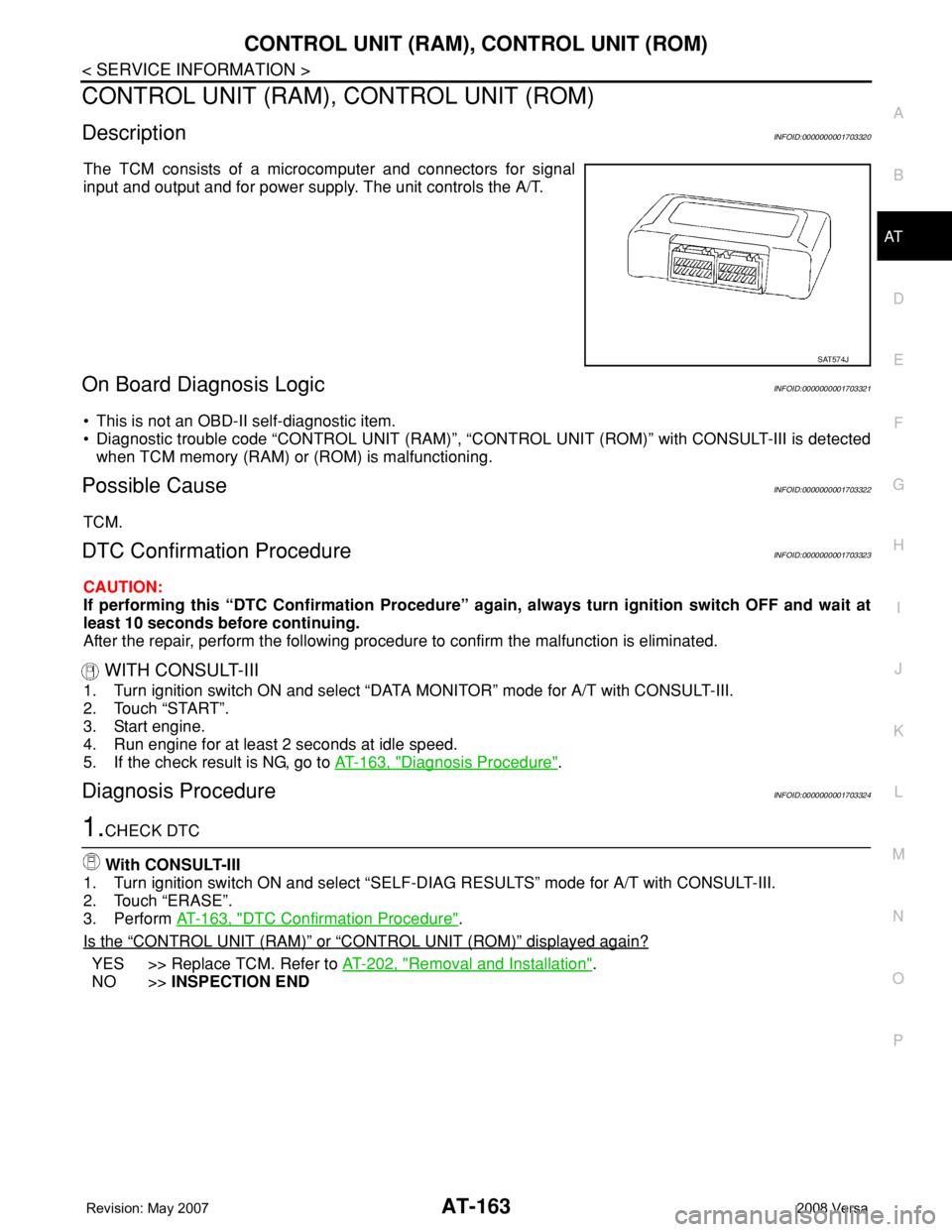
The TCM consists of a microcomputer and connectors for signal
input and output and for power supply. The unit controls the A/T.
On Board Diagnosis LogicINFOID:0000000001703321
• This is not an OBD-II self-diagnostic item.
• Diagnostic trouble code “CONTROL UNIT (RAM)”, “CONTROL UNIT (ROM)” with CONSULT-III is detected
when TCM memory (RAM) or (ROM) is malfunctioning.
Possible CauseINFOID:0000000001703322
TCM.
DTC Confirmation ProcedureINFOID:0000000001703323
CAUTION:
If performing this “DTC Confirmation Procedure” again, always turn ignition switch OFF and wait at
least 10 seconds before continuing.
After the repair, perform the following procedure to confirm the malfunction is eliminated.
WITH CONSULT-III
1. Turn ignition switch ON and select “DATA MONITOR” mode for A/T with CONSULT-III.
2. Touch “START”.
3. Start engine.
4. Run engine for at least 2 seconds at idle speed.
5. If the check result is NG, go to AT-163, "
Diagnosis Procedure".
Diagnosis ProcedureINFOID:0000000001703324
1.CHECK DTC
With CONSULT-III
1. Turn ignition switch ON and select “SELF-DIAG RESULTS” mode for A/T with CONSULT-III.
2. Touch “ERASE”.
3. Perform AT-163, "
DTC Confirmation Procedure".
Is the
“CONTROL UNIT (RAM)” or “CONTROL UNIT (ROM)” displayed again?
YES >> Replace TCM. Refer to AT-202, "Removal and Installation".
NO >>INSPECTION END
SAT574J
Page 353 of 2771
SERVICE DATA AND SPECIFICATIONS (SDS)
AT-341
< SERVICE INFORMATION >
D
E
F
G
H
I
J
K
L
MA
B
AT
N
O
P
SERVICE DATA AND SPECIFICATIONS (SDS)
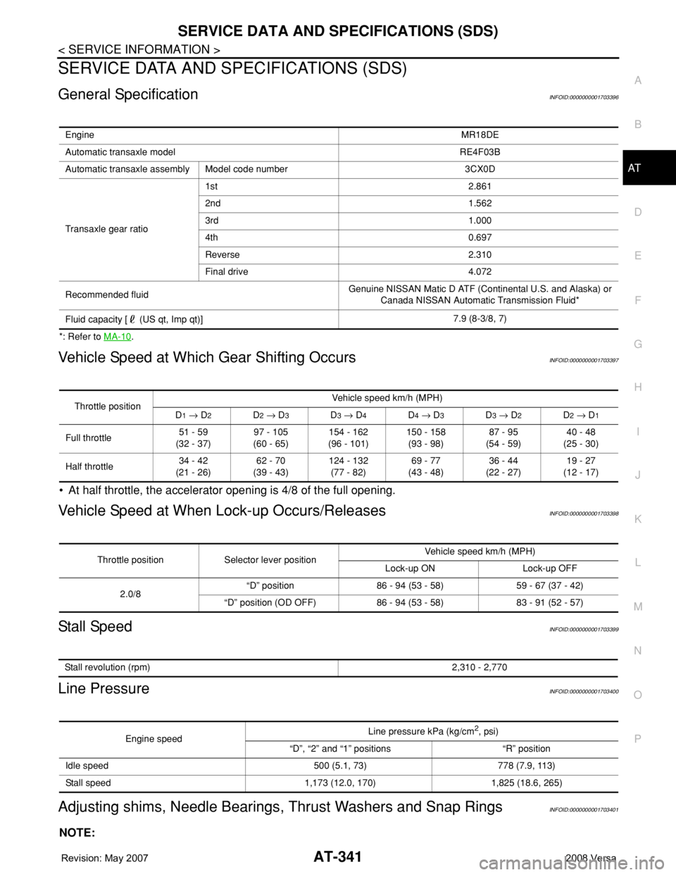
General SpecificationINFOID:0000000001703396
*: Refer to MA-10.
Vehicle Speed at Which Gear Shifting OccursINFOID:0000000001703397
• At half throttle, the accelerator opening is 4/8 of the full opening.
Vehicle Speed at When Lock-up Occurs/ReleasesINFOID:0000000001703398
Stall SpeedINFOID:0000000001703399
Line PressureINFOID:0000000001703400
Adjusting shims, Needle Bearings, Thrust Washers and Snap RingsINFOID:0000000001703401
NOTE:
EngineMR18DE
Automatic transaxle model RE4F03B
Automatic transaxle assembly Model code number 3CX0D
Transaxle gear ratio1st 2.861
2nd 1.562
3rd 1.000
4th 0.697
Reverse 2.310
Final drive 4.072
Recommended fluidGenuine NISSAN Matic D ATF (Continental U.S. and Alaska) or
Canada NISSAN Automatic Transmission Fluid*
Fluid capacity [ (US qt, Imp qt)]7.9 (8-3/8, 7)
Throttle positionVehicle speed km/h (MPH)
D1 → D2D2 → D3D3 → D4D4 → D3D3 → D2D2 → D1
Full throttle51 - 59
(32 - 37)97 - 105
(60 - 65)154 - 162
(96 - 101)150 - 158
(93 - 98)87 - 95
(54 - 59)40 - 48
(25 - 30)
Half throttle34 - 42
(21 - 26)62 - 70
(39 - 43)124 - 132
(77 - 82)69 - 77
(43 - 48)36 - 44
(22 - 27)19 - 27
(12 - 17)
Throttle position Selector lever positionVehicle speed km/h (MPH)
Lock-up ON Lock-up OFF
2.0/8“D” position 86 - 94 (53 - 58) 59 - 67 (37 - 42)
“D” position (OD OFF) 86 - 94 (53 - 58) 83 - 91 (52 - 57)
Stall revolution (rpm)2,310 - 2,770
Engine speedLine pressure kPa (kg/cm2, psi)
“D”, “2” and “1” positions “R” position
Idle speed 500 (5.1, 73) 778 (7.9, 113)
Stall speed 1,173 (12.0, 170) 1,825 (18.6, 265)
Page 407 of 2771
AV-48
< SERVICE INFORMATION >
TELEPHONE
Bluetooth Control Unit Self-Diagnosis Function
INFOID:0000000001704682
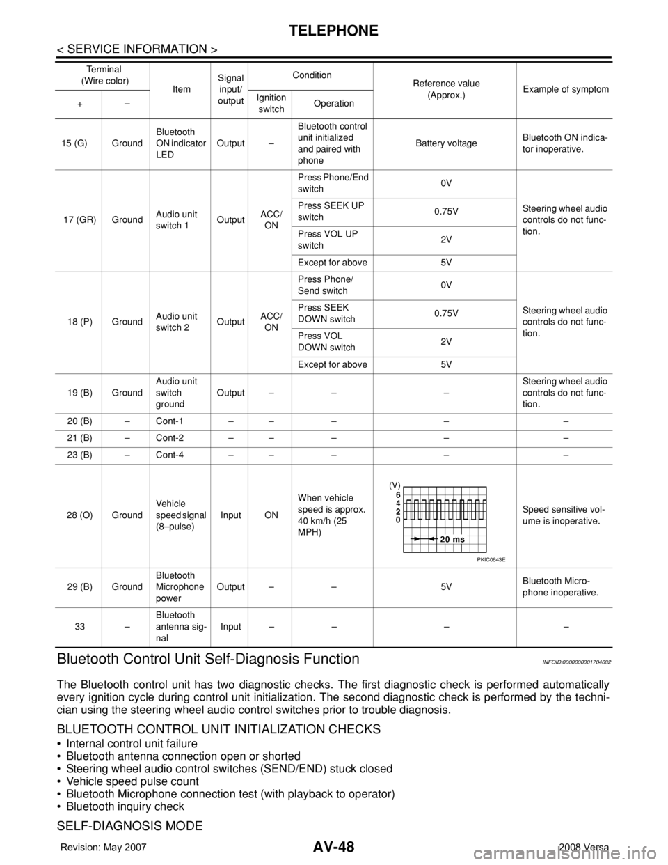
The Bluetooth control unit has two diagnostic checks. The first diagnostic check is performed automatically
every ignition cycle during control unit initialization. The second diagnostic check is performed by the techni-
cian using the steering wheel audio control switches prior to trouble diagnosis.
BLUETOOTH CONTROL UNIT INITIALIZATION CHECKS
• Internal control unit failure
• Bluetooth antenna connection open or shorted
• Steering wheel audio control switches (SEND/END) stuck closed
• Vehicle speed pulse count
• Bluetooth Microphone connection test (with playback to operator)
• Bluetooth inquiry check
SELF-DIAGNOSIS MODE
15 (G) GroundBluetooth
ON indicator
LEDOutput –Bluetooth control
unit initialized
and paired with
phoneBattery voltageBluetooth ON indica-
tor inoperative.
17 (GR) GroundAudio unit
switch 1OutputACC/
ONPress Phone/End
switch 0V
Steering wheel audio
controls do not func-
tion. Press SEEK UP
switch0.75V
Press VOL UP
switch2V
Except for above 5V
18 (P) GroundAudio unit
switch 2OutputACC/
ONPress Phone/
Send switch 0V
Steering wheel audio
controls do not func-
tion. Press SEEK
DOWN switch0.75V
Press VOL
DOWN switch2V
Except for above 5V
19 (B) GroundAudio unit
switch
groundOutput – – –Steering wheel audio
controls do not func-
tion.
20 (B) – Cont-1 – – – – –
21 (B) – Cont-2 – – – – –
23 (B) – Cont-4 – – – – –
28 (O) GroundVehicle
speed signal
(8–pulse)Input ONWhen vehicle
speed is approx.
40 km/h (25
MPH)Speed sensitive vol-
ume is inoperative.
29 (B) GroundBluetooth
Microphone
powerOutput – – 5VBluetooth Micro-
phone inoperative.
33 –Bluetooth
antenna sig-
nalInput – – – – Te r m i n a l
(Wire color)
ItemSignal
input/
outputCondition
Reference value
(Approx.)Example of symptom
+–Ignition
switchOperation
PKIC0643E
Page 408 of 2771
TELEPHONE
AV-49
< SERVICE INFORMATION >
C
D
E
F
G
H
I
J
L
MA
B
AV
N
O
P
1. Turn ignition switch to ACC or ON.
2. Wait for the Bluetooth system to complete initialization and the Bluetooth ON indicator to stop flashing.
This may take up to 10 seconds.
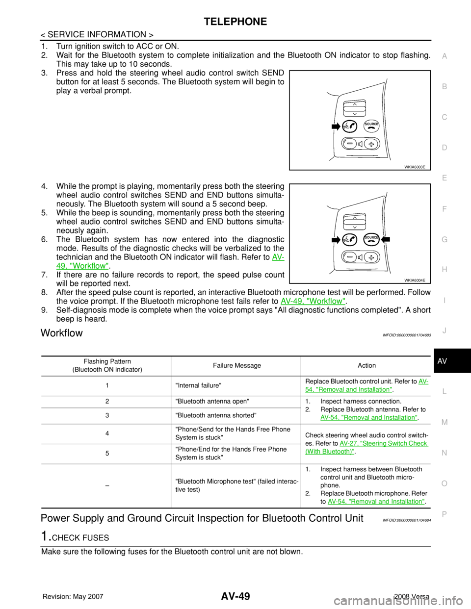
3. Press and hold the steering wheel audio control switch SEND
button for at least 5 seconds. The Bluetooth system will begin to
play a verbal prompt.
4. While the prompt is playing, momentarily press both the steering
wheel audio control switches SEND and END buttons simulta-
neously. The Bluetooth system will sound a 5 second beep.
5. While the beep is sounding, momentarily press both the steering
wheel audio control switches SEND and END buttons simulta-
neously again.
6. The Bluetooth system has now entered into the diagnostic
mode. Results of the diagnostic checks will be verbalized to the
technician and the Bluetooth ON indicator will flash. Refer to AV-
49, "Workflow".
7. If there are no failure records to report, the speed pulse count
will be reported next.
8. After the speed pulse count is reported, an interactive Bluetooth microphone test will be performed. Follow
the voice prompt. If the Bluetooth microphone test fails refer to AV-49, "
Workflow".
9. Self-diagnosis mode is complete when the voice prompt says "All diagnostic functions completed". A short
beep is heard.
WorkflowINFOID:0000000001704683
Power Supply and Ground Circuit Inspection for Bluetooth Control UnitINFOID:0000000001704684
1.CHECK FUSES
Make sure the following fuses for the Bluetooth control unit are not blown.
WKIA6003E
WKIA6004E
Flashing Pattern
(Bluetooth ON indicator)Failure Message Action
1 "Internal failure"Replace Bluetooth control unit. Refer to AV-
54, "Removal and Installation".
2 "Bluetooth antenna open" 1. Inspect harness connection.
2. Replace Bluetooth antenna. Refer to
AV- 5 4 , "
Removal and Installation". 3 "Bluetooth antenna shorted"
4"Phone/Send for the Hands Free Phone
System is stuck"Check steering wheel audio control switch-
es. Refer to AV- 2 7 , "
Steering Switch Check
(With Bluetooth)".
5"Phone/End for the Hands Free Phone
System is stuck"
–"Bluetooth Microphone test" (failed interac-
tive test)1. Inspect harness between Bluetooth
control unit and Bluetooth micro-
phone.
2. Replace Bluetooth microphone. Refer
to AV- 5 4 , "
Removal and Installation".