Page 287 of 2771

REPAIR FOR COMPONENT PARTS
AT-275
< SERVICE INFORMATION >
D
E
F
G
H
I
J
K
L
MA
B
AT
N
O
P Va l v e Sp r i n g s
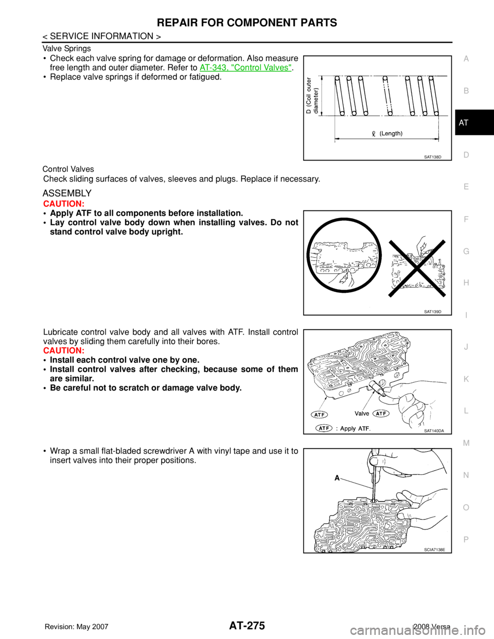
• Check each valve spring for damage or deformation. Also measure
free length and outer diameter. Refer to AT-343, "
Control Valves".
• Replace valve springs if deformed or fatigued.
Control Valves
Check sliding surfaces of valves, sleeves and plugs. Replace if necessary.
ASSEMBLY
CAUTION:
• Apply ATF to all components before installation.
• Lay control valve body down when installing valves. Do not
stand control valve body upright.
Lubricate control valve body and all valves with ATF. Install control
valves by sliding them carefully into their bores.
CAUTION:
• Install each control valve one by one.
• Install control valves after checking, because some of them
are similar.
• Be careful not to scratch or damage valve body.
• Wrap a small flat-bladed screwdriver A with vinyl tape and use it to
insert valves into their proper positions.
SAT138D
SAT139D
SAT140DA
SCIA7138E
Page 288 of 2771

AT-276
< SERVICE INFORMATION >
REPAIR FOR COMPONENT PARTS
• Install retainer plates (1).
- While pushing plug or return spring, install retainer plate (1) using
a flat-bladed screwdriver A.
1-2 Accumulator Valve
• Install 1-2 accumulator valve (1), 1-2 accumulator valve spring and
plug. Align 1-2 accumulator retainer plate (2) from opposite side of
control valve body.
• Install 1-2 accumulator valve piston spring (3), 1-2 accumulator
piston (4), plug (5) and retainer plate (6).
Retainer Plate (Control Valve Upper Body)
Install proper retainer plates. Refer to "COMPONENTS".
Unit: mm (in)
Control Valve Lower BodyINFOID:0000000001703382
COMPONENTS
SCIA7139E
SCIA7182E
Lo-
cat-
ionRetainer plate designation Width “A” Length “B”
L14 Pilot valve
6.0 (0.236)21.5 (0.846)
L151-2 accumulator valve
40.5 (1.594)
1-2 accumulator piston
L16 1st reducing valve
21.5 (0.846)
L17 3-2 timing valve
L18 Overrun clutch reducing valve 24.0 (0.945)
L19 Torque converter relief valve 21.5 (0.846)
L20 Torque converter clutch control valve 28.0 (1.102)
L21 Cooler check valve 24.0 (0.945)
SAT086F
Page 289 of 2771
REPAIR FOR COMPONENT PARTS
AT-277
< SERVICE INFORMATION >
D
E
F
G
H
I
J
K
L
MA
B
AT
N
O
P
1. Retainer plate 2. Pressure modifier piston spring 3. Pressure modifier piston
4. Parallel pin 5. Sleeve 6. Pressure modifier valve spring
7. Pressure modifier valve 8. Control valve lower body 9. Manual valve
10. Pressure regulator valve 11. Pressure regulator valve spring 12. Spring seat
13. Plug 14. Retainer plate 15. Sleeve
16. Overrun clutch control valve spring 17. Overrun clutch control valve 18. Plug
SCIA2959J
Page 290 of 2771

AT-278
< SERVICE INFORMATION >
REPAIR FOR COMPONENT PARTS
DISASSEMBLY
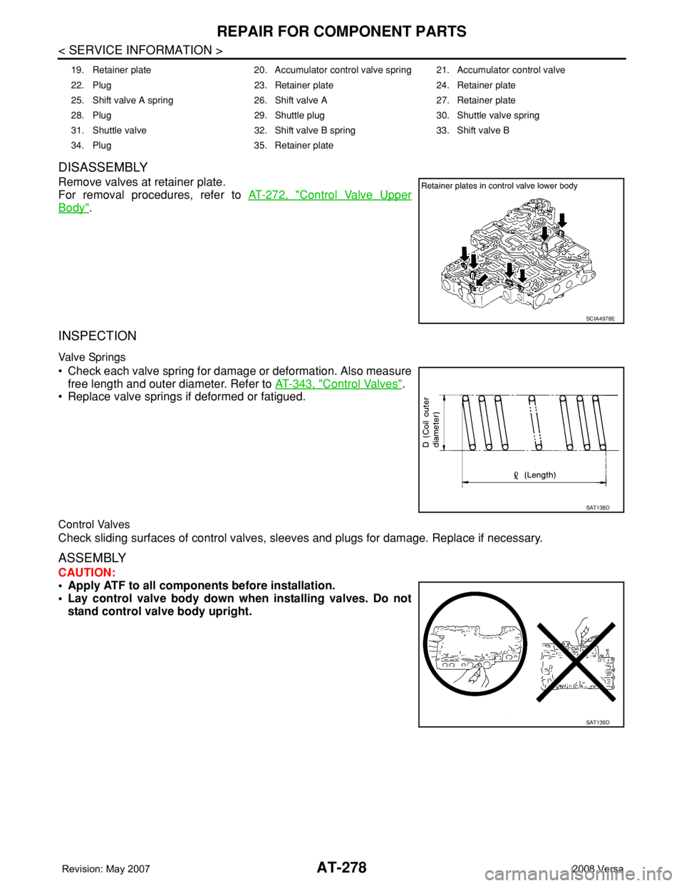
Remove valves at retainer plate.
For removal procedures, refer to AT-272, "
Control Valve Upper
Body".
INSPECTION
Valve Springs
• Check each valve spring for damage or deformation. Also measure
free length and outer diameter. Refer to AT-343, "
Control Valves".
• Replace valve springs if deformed or fatigued.
Control Valves
Check sliding surfaces of control valves, sleeves and plugs for damage. Replace if necessary.
ASSEMBLY
CAUTION:
• Apply ATF to all components before installation.
• Lay control valve body down when installing valves. Do not
stand control valve body upright.
19. Retainer plate 20. Accumulator control valve spring 21. Accumulator control valve
22. Plug 23. Retainer plate 24. Retainer plate
25. Shift valve A spring 26. Shift valve A 27. Retainer plate
28. Plug 29. Shuttle plug 30. Shuttle valve spring
31. Shuttle valve 32. Shift valve B spring 33. Shift valve B
34. Plug 35. Retainer plate
SCIA4978E
SAT138D
SAT139D
Page 291 of 2771

REPAIR FOR COMPONENT PARTS
AT-279
< SERVICE INFORMATION >
D
E
F
G
H
I
J
K
L
MA
B
AT
N
O
P
Install control valves.
For installation procedures, refer to AT-272, "
Control Valve Upper
Body".
Retainer Plate (Control Valve Lower Body)
Install proper retainer plates. Refer to "COMPONENTS".
Unit: mm (in)
Reverse ClutchINFOID:0000000001703383
COMPONENTS
DISASSEMBLY
SCIA4978E
Lo-
cat-
ionRetainer plate designation Width “A” Length “B” Type
L3 Pressure regulator valve
6.0
(0.236)28.0
(1.102)I L4 Overrun clutch control valve
L5 Accumulator control valve
L6 Shift valve A
L7 Shuttle valve
L12 Shift valve B17.0
(0.669)24.0
(0.945)II
L13 Pressure modifier valve6.0
(0.236)28.0
(1.102)I
SAT089F
1. Reverse clutch drum 2. D-ring 3. Seal lip
4. Reverse clutch piston 5. Spring retainer assembly 6. Snap ring
7. Dish plate 8. Driven plate 9. Retaining plate
10. Snap ring 11. Drive plate
Refer to GI section to make sure icons (symbol marks) in the figure. Refer to GI-8, "
Component".
SCIA6939J
Page 292 of 2771

AT-280
< SERVICE INFORMATION >
REPAIR FOR COMPONENT PARTS
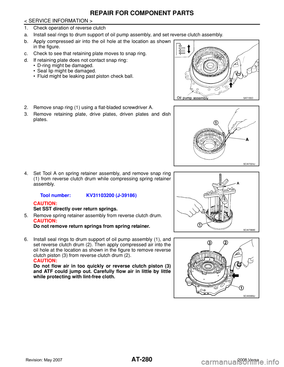
1. Check operation of reverse clutch
a. Install seal rings to drum support of oil pump assembly, and set reverse clutch assembly.
b. Apply compressed air into the oil hole at the location as shown
in the figure.
c. Check to see that retaining plate moves to snap ring.
d. If retaining plate does not contact snap ring:
• D-ring might be damaged.
• Seal lip might be damaged.
• Fluid might be leaking past piston check ball.
2. Remove snap ring (1) using a flat-bladed screwdriver A.
3. Remove retaining plate, drive plates, driven plates and dish
plates.
4. Set Tool A on spring retainer assembly, and remove snap ring
(1) from reverse clutch drum while compressing spring retainer
assembly.
CAUTION:
Set SST directly over return springs.
5. Remove spring retainer assembly from reverse clutch drum.
CAUTION:
Do not remove return springs from spring retainer.
6. Install seal rings to drum support of oil pump assembly (1), and
set reverse clutch drum (2). Then apply compressed air into the
oil hole at the location as shown in the figure to remove reverse
clutch piston (3) from reverse clutch drum (2).
CAUTION:
Do not flow air in too quickly or reverse clutch piston (3)
and ATF could jump out. Carefully flow air in little by little
while protecting with lint-free cloth.
SAT155D
SCIA7024J
Tool number: KV31103200 (J-39186)
SCIA7988E
SCIA5999J
Page 293 of 2771

REPAIR FOR COMPONENT PARTS
AT-281
< SERVICE INFORMATION >
D
E
F
G
H
I
J
K
L
MA
B
AT
N
O
P
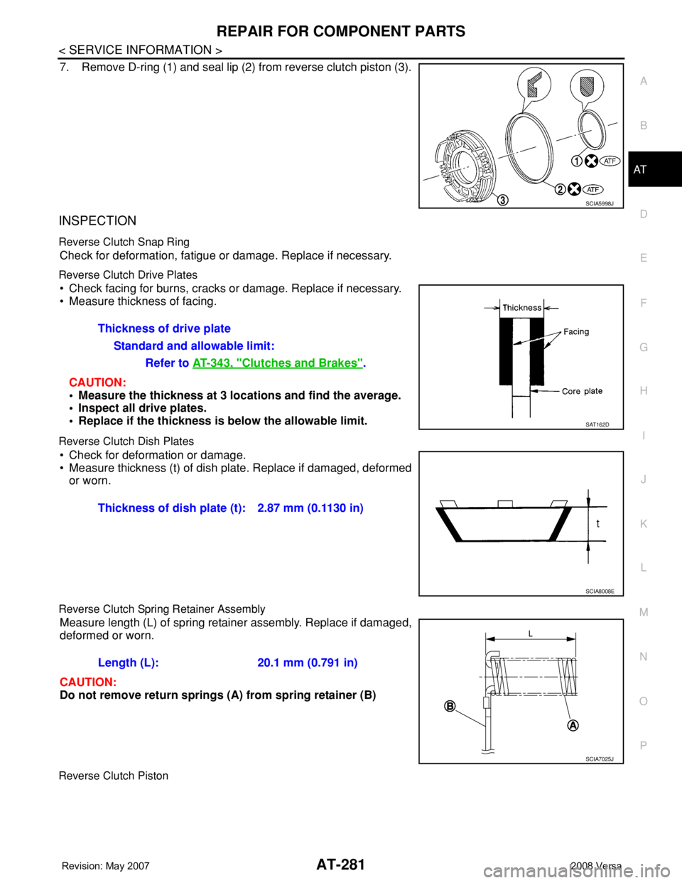
7. Remove D-ring (1) and seal lip (2) from reverse clutch piston (3).
INSPECTION
Reverse Clutch Snap Ring
Check for deformation, fatigue or damage. Replace if necessary.
Reverse Clutch Drive Plates
• Check facing for burns, cracks or damage. Replace if necessary.
• Measure thickness of facing.
CAUTION:
• Measure the thickness at 3 locations and find the average.
• Inspect all drive plates.
• Replace if the thickness is below the allowable limit.
Reverse Clutch Dish Plates
• Check for deformation or damage.
• Measure thickness (t) of dish plate. Replace if damaged, deformed
or worn.
Reverse Clutch Spring Retainer Assembly
Measure length (L) of spring retainer assembly. Replace if damaged,
deformed or worn.
CAUTION:
Do not remove return springs (A) from spring retainer (B)
Reverse Clutch Piston
SCIA5998J
Thickness of drive plate
Standard and allowable limit:
Refer to AT-343, "
Clutches and Brakes".
SAT162D
Thickness of dish plate (t): 2.87 mm (0.1130 in)
SCIA8008E
Length (L): 20.1 mm (0.791 in)
SCIA7025J
Page 294 of 2771
AT-282
< SERVICE INFORMATION >
REPAIR FOR COMPONENT PARTS
• Make sure that check balls are not fixed.
• Apply compressed air to check ball oil hole opposite from return
spring. Make sure there is no air leakage.
• Apply compressed air to oil hole on return spring side to make sure
that air leaks past ball.
Reverse Clutch Drum
Check for deformation or damage. Replace if necessary.
ASSEMBLY
1. Install D-ring (1) and seal lip (2) on reverse clutch piston (3).
CAUTION:
Be careful with the direction of seal lip (2).
2. Install reverse clutch piston by turning it slowly.
CAUTION:
Apply ATF to inner surface of reverse clutch drum.
3. Install spring retainer assembly (1) to reverse clutch piston (2).
SAT164D
SCIA5998J
SAT159D
SCIA6000J