2008 NISSAN LATIO engine
[x] Cancel search: enginePage 1034 of 2771
COMBINATION METERS
DI-13
< SERVICE INFORMATION >
C
D
E
F
G
H
I
J
L
MA
B
DI
N
O
P
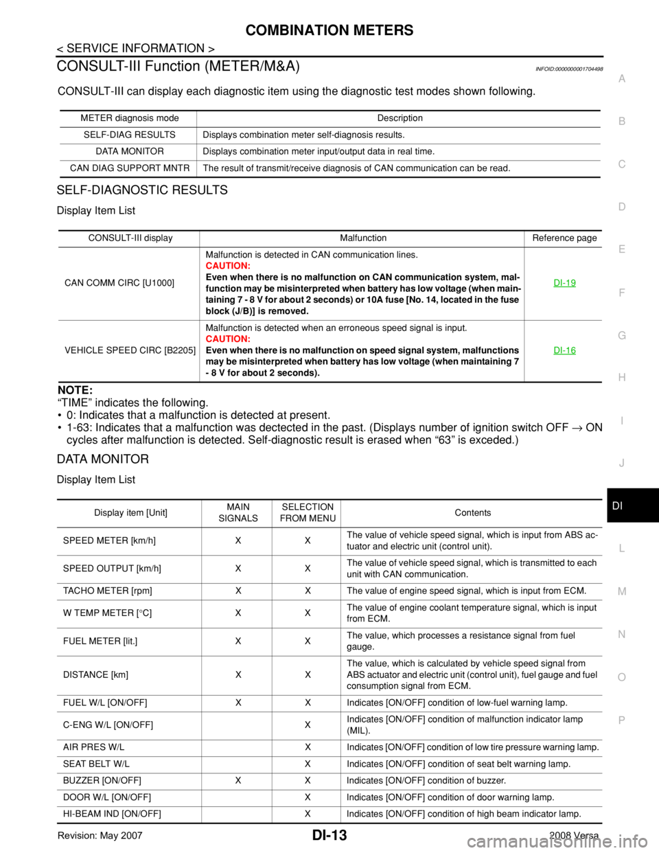
CONSULT-III Function (METER/M&A)INFOID:0000000001704498
CONSULT-III can display each diagnostic item using the diagnostic test modes shown following.
SELF-DIAGNOSTIC RESULTS
Display Item List
NOTE:
“TIME” indicates the following.
• 0: Indicates that a malfunction is detected at present.
• 1-63: Indicates that a malfunction was dectected in the past. (Displays number of ignition switch OFF → ON
cycles after malfunction is detected. Self-diagnostic result is erased when “63” is exceded.)
DATA MONITOR
Display Item List
METER diagnosis mode Description
SELF-DIAG RESULTS Displays combination meter self-diagnosis results.
DATA MONITOR Displays combination meter input/output data in real time.
CAN DIAG SUPPORT MNTR The result of transmit/receive diagnosis of CAN communication can be read.
CONSULT-III display Malfunction Reference page
CAN COMM CIRC [U1000]Malfunction is detected in CAN communication lines.
CAUTION:
Even when there is no malfunction on CAN communication system, mal-
function may be misinterpreted when battery has low voltage (when main-
taining 7 - 8 V for about 2 seconds) or 10A fuse [No. 14, located in the fuse
block (J/B)] is removed.DI-19
VEHICLE SPEED CIRC [B2205]Malfunction is detected when an erroneous speed signal is input.
CAUTION:
Even when there is no malfunction on speed signal system, malfunctions
may be misinterpreted when battery has low voltage (when maintaining 7
- 8 V for about 2 seconds).DI-16
Display item [Unit]MAIN
SIGNALSSELECTION
FROM MENUContents
SPEED METER [km/h] X XThe value of vehicle speed signal, which is input from ABS ac-
tuator and electric unit (control unit).
SPEED OUTPUT [km/h] X XThe value of vehicle speed signal, which is transmitted to each
unit with CAN communication.
TACHO METER [rpm] X X The value of engine speed signal, which is input from ECM.
W TEMP METER [°C] X XThe value of engine coolant temperature signal, which is input
from ECM.
FUEL METER [lit.] X XThe value, which processes a resistance signal from fuel
gauge.
DISTANCE [km] X XThe value, which is calculated by vehicle speed signal from
ABS actuator and electric unit (control unit), fuel gauge and fuel
consumption signal from ECM.
FUEL W/L [ON/OFF] X X Indicates [ON/OFF] condition of low-fuel warning lamp.
C-ENG W/L [ON/OFF] XIndicates [ON/OFF] condition of malfunction indicator lamp
(MIL).
AIR PRES W/L X Indicates [ON/OFF] condition of low tire pressure warning lamp.
SEAT BELT W/L X Indicates [ON/OFF] condition of seat belt warning lamp.
BUZZER [ON/OFF] X X Indicates [ON/OFF] condition of buzzer.
DOOR W/L [ON/OFF] X Indicates [ON/OFF] condition of door warning lamp.
HI-BEAM IND [ON/OFF] X Indicates [ON/OFF] condition of high beam indicator lamp.
Page 1036 of 2771
COMBINATION METERS
DI-15
< SERVICE INFORMATION >
C
D
E
F
G
H
I
J
L
MA
B
DI
N
O
P
NO >> Check power supply and ground circuit of combination meter. Refer to DI-15, "Power Supply and
Ground Circuit Inspection" .
2.CHECK COMBINATION METER (CONSULT-III)
Select “METER/M&A” on CONSULT-III and perform self-diagnosis of combination meter. Refer to DI-13,
"CONSULT-III Function (METER/M&A)" .
Self
-diagnostic results content
No malfunction detected>> Refer to DI-15, "Symptom Chart" .
Malfunction detected>> Refer to DI-13, "
CONSULT-III Function (METER/M&A)" .
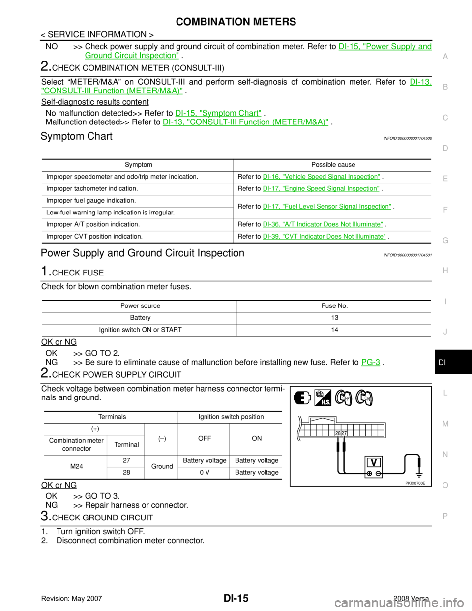
Symptom ChartINFOID:0000000001704500
Power Supply and Ground Circuit InspectionINFOID:0000000001704501
1.CHECK FUSE
Check for blown combination meter fuses.
OK or NG
OK >> GO TO 2.
NG >> Be sure to eliminate cause of malfunction before installing new fuse. Refer to PG-3
.
2.CHECK POWER SUPPLY CIRCUIT
Check voltage between combination meter harness connector termi-
nals and ground.
OK or NG
OK >> GO TO 3.
NG >> Repair harness or connector.
3.CHECK GROUND CIRCUIT
1. Turn ignition switch OFF.
2. Disconnect combination meter connector.
Symptom Possible cause
Improper speedometer and odo/trip meter indication. Refer to DI-16, "
Vehicle Speed Signal Inspection" .
Improper tachometer indication. Refer to DI-17, "
Engine Speed Signal Inspection" .
Improper fuel gauge indication.
Refer to DI-17, "
Fuel Level Sensor Signal Inspection" .
Low-fuel warning lamp indication is irregular.
Improper A/T position indication. Refer to DI-36, "
A/T Indicator Does Not Illuminate" .
Improper CVT position indication. Refer to DI-39, "
CVT Indicator Does Not Illuminate" .
Power source Fuse No.
Battery 13
Ignition switch ON or START 14
Terminals Ignition switch position
(+)
(–) OFF ON
Combination meter
connectorTe r m i n a l
M2427
GroundBattery voltage Battery voltage
28 0 V Battery voltage
PKIC0700E
Page 1037 of 2771
DI-16
< SERVICE INFORMATION >
COMBINATION METERS
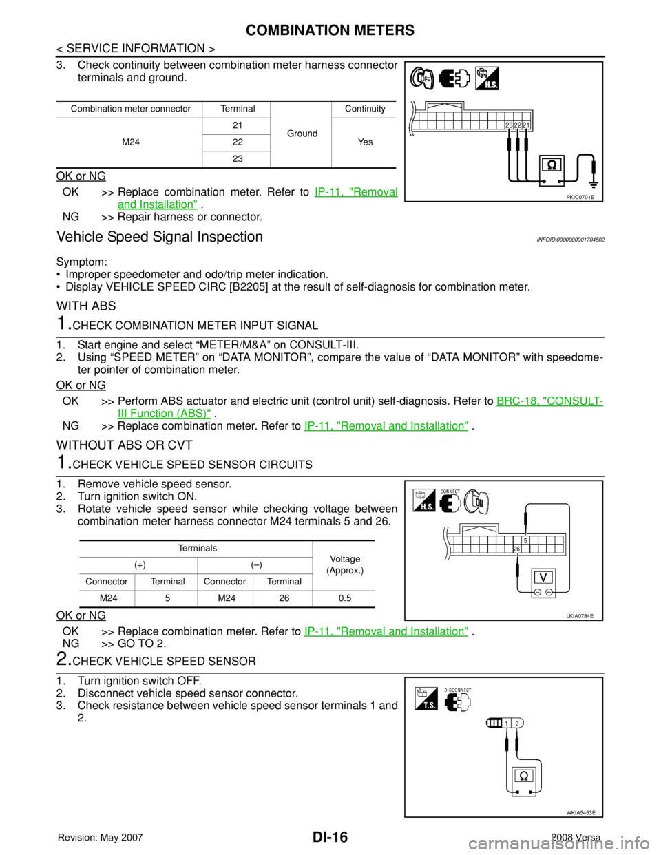
3. Check continuity between combination meter harness connector
terminals and ground.
OK or NG
OK >> Replace combination meter. Refer to IP-11, "Removal
and Installation" .
NG >> Repair harness or connector.
Vehicle Speed Signal InspectionINFOID:0000000001704502
Symptom:
• Improper speedometer and odo/trip meter indication.
• Display VEHICLE SPEED CIRC [B2205] at the result of self-diagnosis for combination meter.
WITH ABS
1.CHECK COMBINATION METER INPUT SIGNAL
1. Start engine and select “METER/M&A” on CONSULT-III.
2. Using “SPEED METER” on “DATA MONITOR”, compare the value of “DATA MONITOR” with speedome-
ter pointer of combination meter.
OK or NG
OK >> Perform ABS actuator and electric unit (control unit) self-diagnosis. Refer to BRC-18, "CONSULT-
III Function (ABS)" .
NG >> Replace combination meter. Refer to IP-11, "
Removal and Installation" .
WITHOUT ABS OR CVT
1.CHECK VEHICLE SPEED SENSOR CIRCUITS
1. Remove vehicle speed sensor.
2. Turn ignition switch ON.
3. Rotate vehicle speed sensor while checking voltage between
combination meter harness connector M24 terminals 5 and 26.
OK or NG
OK >> Replace combination meter. Refer to IP-11, "Removal and Installation" .
NG >> GO TO 2.
2.CHECK VEHICLE SPEED SENSOR
1. Turn ignition switch OFF.
2. Disconnect vehicle speed sensor connector.
3. Check resistance between vehicle speed sensor terminals 1 and
2.
Combination meter connector Terminal
GroundContinuity
M2421
Ye s 22
23
PKIC0701E
Te r m i n a l s
Voltag e
(Approx.) (+) (–)
Connector Terminal Connector Terminal
M24 5 M24 26 0.5
LKIA0784E
WKIA5453E
Page 1038 of 2771
COMBINATION METERS
DI-17
< SERVICE INFORMATION >
C
D
E
F
G
H
I
J
L
MA
B
DI
N
O
P
OK or NG
OK >> Check harness or connector between combination meter and vehicle speed sensor.
NG >> Replace vehicle speed sensor.
WITH CVT, WITHOUT ABS
1.CHECK COMBINATION METER INPUT SIGNAL
1. Start engine and select “METER/M&A” on CONSULT-III.
2. Using “SPEED METER” on “DATA MONITOR”, compare the value of “DATA MONITOR” with speedome-
ter pointer of combination meter.
OK or NG
OK >> Perform TCM self-diagnosis. Refer to CVT-47, "CONSULT-III Function (TRANSMISSION)" .
NG >> Replace combination meter. Refer to IP-11, "
Removal and Installation" .
Engine Speed Signal InspectionINFOID:0000000001704503
Symptom: Improper tachometer indication.
1.CHECK COMBINATION METER INPUT SIGNAL
1. Start engine and select “METER/M&A” on CONSULT-III.
2. Using “TACHO METER” on “DATA MONITOR”, compare the value of “DATA MONITOR” with tachometer
pointer of combination meter.
OK or NG
OK >> Perform ECM self-diagnosis. Refer to EC-109, "CONSULT-II Function (ENGINE)" .
NG >> Replace combination meter. Refer to IP-11, "
Removal and Installation" .
Fuel Level Sensor Signal InspectionINFOID:0000000001704504
Symptom:
• Improper fuel gauge indication.
• Low-fuel warning lamp indication is irregular.
NOTE:
The following symptoms do not indicate a malfunction.
• Depending on vehicle position or driving circumstance, the fuel level in the tank shifts and the indication may
fluctuate.
• If the vehicle is fueled with the ignition switch ON, the indication will update slowly.
• If the vehicle is tilted when the ignition switch is turned ON, fuel in the tank may flow to one direction result-
ing in a change of reading.
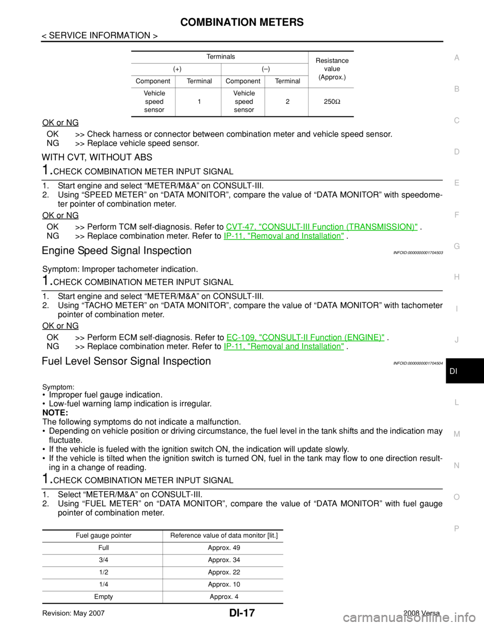
1.CHECK COMBINATION METER INPUT SIGNAL
1. Select “METER/M&A” on CONSULT-III.
2. Using “FUEL METER” on “DATA MONITOR”, compare the value of “DATA MONITOR” with fuel gauge
pointer of combination meter.
Te r m i n a l s
Resistance
value
(Approx.) (+) (–)
Component Terminal Component Terminal
Ve h i c l e
speed
sensor1Vehicle
speed
sensor2250Ω
Fuel gauge pointer Reference value of data monitor [lit.]
Full Approx. 49
3/4 Approx. 34
1/2 Approx. 22
1/4 Approx. 10
Empty Approx. 4
Page 1052 of 2771
WARNING LAMPS
DI-31
< SERVICE INFORMATION >
C
D
E
F
G
H
I
J
L
MA
B
DI
N
O
P
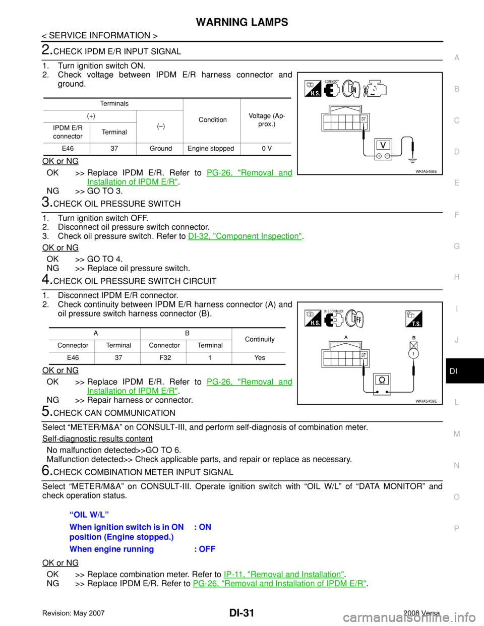
2.CHECK IPDM E/R INPUT SIGNAL
1. Turn ignition switch ON.
2. Check voltage between IPDM E/R harness connector and
ground.
OK or NG
OK >> Replace IPDM E/R. Refer to PG-26, "Removal and
Installation of IPDM E/R".
NG >> GO TO 3.
3.CHECK OIL PRESSURE SWITCH
1. Turn ignition switch OFF.
2. Disconnect oil pressure switch connector.
3. Check oil pressure switch. Refer to DI-32, "
Component Inspection".
OK or NG
OK >> GO TO 4.
NG >> Replace oil pressure switch.
4.CHECK OIL PRESSURE SWITCH CIRCUIT
1. Disconnect IPDM E/R connector.
2. Check continuity between IPDM E/R harness connector (A) and
oil pressure switch harness connector (B).
OK or NG
OK >> Replace IPDM E/R. Refer to PG-26, "Removal and
Installation of IPDM E/R".
NG >> Repair harness or connector.
5.CHECK CAN COMMUNICATION
Select “METER/M&A” on CONSULT-III, and perform self-diagnosis of combination meter.
Self
-diagnostic results content
No malfunction detected>>GO TO 6.
Malfunction detected>> Check applicable parts, and repair or replace as necessary.
6.CHECK COMBINATION METER INPUT SIGNAL
Select “METER/M&A” on CONSULT-III. Operate ignition switch with “OIL W/L” of “DATA MONITOR” and
check operation status.
OK or NG
OK >> Replace combination meter. Refer to IP-11, "Removal and Installation".
NG >> Replace IPDM E/R. Refer to PG-26, "
Removal and Installation of IPDM E/R".
Te r m i n a l s
ConditionVoltage (Ap-
prox.) (+)
(–)
IPDM E/R
connectorTe r m i n a l
E46 37 Ground Engine stopped 0 V
WKIA5458E
AB
Continuity
Connector Terminal Connector Terminal
E46 37 F32 1 Yes
WKIA5459E
“OIL W/L”
When ignition switch is in ON
position (Engine stopped.): ON
When engine running : OFF
Page 1054 of 2771
![NISSAN LATIO 2008 Service Repair Manual WARNING LAMPS
DI-33
< SERVICE INFORMATION >
C
D
E
F
G
H
I
J
L
MA
B
DI
N
O
P
Check continuity between oil pressure switch and ground.
Condition
Oil pressure [kPa (bar, kg/cm2, psi)]Continuity
Engine st NISSAN LATIO 2008 Service Repair Manual WARNING LAMPS
DI-33
< SERVICE INFORMATION >
C
D
E
F
G
H
I
J
L
MA
B
DI
N
O
P
Check continuity between oil pressure switch and ground.
Condition
Oil pressure [kPa (bar, kg/cm2, psi)]Continuity
Engine st](/manual-img/5/57360/w960_57360-1053.png)
WARNING LAMPS
DI-33
< SERVICE INFORMATION >
C
D
E
F
G
H
I
J
L
MA
B
DI
N
O
P
Check continuity between oil pressure switch and ground.
Condition
Oil pressure [kPa (bar, kg/cm2, psi)]Continuity
Engine stopped Less than 29 (0.3, 0.3, 4) Yes
Engine running More than 29 (0.3, 0.3, 4) No
ELF0044D
Page 1075 of 2771

EC-1
ENGINE
C
D
E
F
G
H
I
J
K
L
M
SECTION EC
A
EC
N
O
P
CONTENTS
ENGINE CONTROL SYSTEM
SERVICE INFORMATION ............................9
INDEX FOR DTC .................................................9
DTC No. Index ..........................................................9
Alphabetical Index ...................................................12
PRECAUTIONS ..................................................16
Precaution for Supplemental Restraint System
(SRS) "AIR BAG" and "SEAT BELT PRE-TEN-
SIONER" .................................................................
16
Precaution for Procedure without Cowl Top Cover ....16
On Board Diagnosis (OBD) System of Engine and
A/T, CVT .................................................................
16
Precaution ...............................................................17
PREPARATION ..................................................20
Special Service Tool ...............................................20
Commercial Service Tool ........................................21
ENGINE CONTROL SYSTEM ............................22
Schematic ...............................................................22
Multiport Fuel Injection (MFI) System .....................22
Electronic Ignition (EI) System ................................25
Fuel Cut Control (at No Load and High Engine
Speed) .....................................................................
25
AIR CONDITIONING CUT CONTROL ...............27
Input/Output Signal Chart ........................................27
System Description .................................................27
AUTOMATIC SPEED CONTROL DEVICE
(ASCD) ...............................................................
28
System Description .................................................28
Component Description ...........................................29
CAN COMMUNICATION ....................................30
System Description .................................................30
EVAPORATIVE EMISSION SYSTEM ................31
Description ..............................................................31
Component Inspection ............................................33
Removal and Installation .........................................35
How to Detect Fuel Vapor Leakage .........................35
ON BOARD REFUELING VAPOR RECOV-
ERY (ORVR) ......................................................
38
System Description ..................................................38
Diagnosis Procedure ...............................................38
Component Inspection .............................................40
POSITIVE CRANKCASE VENTILATION .........43
Description ...............................................................43
Component Inspection .............................................43
NVIS (NISSAN VEHICLE IMMOBILIZER SYS-
TEM-NATS) .......................................................
45
Description ...............................................................45
ON BOARD DIAGNOSTIC (OBD) SYSTEM ....46
Introduction ..............................................................46
Two Trip Detection Logic .........................................46
Emission-related Diagnostic Information .................47
Malfunction Indicator Lamp (MIL) ............................60
OBD System Operation Chart .................................63
BASIC SERVICE PROCEDURE .......................69
Basic Inspection ......................................................69
Idle Speed and Ignition Timing Check .....................73
Procedure After Replacing ECM .............................75
VIN Registration ......................................................75
Accelerator Pedal Released Position Learning .......76
Throttle Valve Closed Position Learning .................76
Idle Air Volume Learning .........................................76
Fuel Pressure Check ...............................................78
TROUBLE DIAGNOSIS ....................................81
Trouble Diagnosis Introduction ................................81
DTC Inspection Priority Chart ..................................86
Fail-Safe Chart ........................................................87
Symptom Matrix Chart .............................................88
Engine Control Component Parts Location .............93
Vacuum Hose Drawing ............................................99
Circuit Diagram ......................................................100
ECM Harness Connector Terminal Layout ............102
Page 1076 of 2771

EC-2
ECM Terminal and Reference Value .....................102
CONSULT-II Function (ENGINE) ..........................109
Generic Scan Tool (GST) Function .......................119
CONSULT-II Reference Value in Data Monitor
Mode ......................................................................
121
Major Sensor Reference Graph in Data Monitor
Mode ......................................................................
124
TROUBLE DIAGNOSIS - SPECIFICATION
VALUE .............................................................
127
Description .............................................................127
Testing Condition ...................................................127
Inspection Procedure .............................................127
Diagnosis Procedure .............................................127
TROUBLE DIAGNOSIS FOR INTERMITTENT
INCIDENT ........................................................
136
Description .............................................................136
Diagnosis Procedure .............................................136
POWER SUPPLY AND GROUND CIRCUIT ...137
Wiring Diagram ......................................................137
Diagnosis Procedure .............................................138
Ground Inspection .................................................142
DTC U1000, U1001 CAN COMMUNICATION
LINE .................................................................
143
Description .............................................................143
On Board Diagnosis Logic .....................................143
DTC Confirmation Procedure ................................143
Wiring Diagram ......................................................144
Diagnosis Procedure .............................................144
DTC U1010 CAN COMMUNICATION .............145
Description .............................................................145
On Board Diagnosis Logic .....................................145
DTC Confirmation Procedure ................................145
Diagnosis Procedure .............................................145
DTC P0011 IVT CONTROL .............................147
Description .............................................................147
CONSULT-II Reference Value in Data Monitor
Mode ......................................................................
147
On Board Diagnosis Logic .....................................148
DTC Confirmation Procedure ................................148
Diagnosis Procedure .............................................149
Component Inspection ...........................................150
Removal and Installation .......................................150
DTC P0031, P0032 A/F SENSOR 1 HEATER .151
Description .............................................................151
CONSULT-II Reference Value in Data Monitor
Mode ......................................................................
151
On Board Diagnosis Logic .....................................151
DTC Confirmation Procedure ................................151
Wiring Diagram ......................................................152
Diagnosis Procedure .............................................153
Component Inspection ...........................................154
Removal and Installation .......................................155
DTC P0037, P0038 HO2S2 HEATER ..............156
Description ............................................................156
CONSULT-II Reference Value in Data Monitor
Mode .....................................................................
156
On Board Diagnosis Logic ....................................156
DTC Confirmation Procedure ................................156
Wiring Diagram .....................................................158
Diagnosis Procedure .............................................159
Component Inspection ..........................................160
Removal and Installation .......................................161
DTC P0075 IVT CONTROL SOLENOID
VALVE ..............................................................
162
Component Description ........................................162
CONSULT-II Reference Value in Data Monitor
Mode .....................................................................
162
On Board Diagnosis Logic ....................................162
DTC Confirmation Procedure ................................162
Wiring Diagram .....................................................163
Diagnosis Procedure .............................................164
Component Inspection ..........................................165
Removal and Installation .......................................166
DTC P0101 MAF SENSOR ..............................167
Component Description ........................................167
CONSULT-II Reference Value in Data Monitor
Mode .....................................................................
167
On Board Diagnosis Logic ....................................167
DTC Confirmation Procedure ................................167
Overall Function Check .........................................169
Wiring Diagram .....................................................170
Diagnosis Procedure .............................................171
Component Inspection ..........................................173
Removal and Installation .......................................174
DTC P0102, P0103 MAF SENSOR ..................175
Component Description ........................................175
CONSULT-II Reference Value in Data Monitor
Mode .....................................................................
175
On Board Diagnosis Logic ....................................175
DTC Confirmation Procedure ................................175
Wiring Diagram .....................................................177
Diagnosis Procedure .............................................178
Component Inspection ..........................................180
Removal and Installation .......................................181
DTC P0112, P0113 IAT SENSOR ....................182
Component Description ........................................182
On Board Diagnosis Logic ....................................182
DTC Confirmation Procedure ................................182
Wiring Diagram .....................................................184
Diagnosis Procedure .............................................184
Component Inspection ..........................................186
Removal and Installation .......................................186
DTC P0117, P0118 ECT SENSOR ...................187
Component Description ........................................187
On Board Diagnosis Logic ....................................187
DTC Confirmation Procedure ................................188
Wiring Diagram .....................................................189