2008 NISSAN LATIO warning
[x] Cancel search: warningPage 2709 of 2771

WT-1
SUSPENSION
C
D
F
G
H
I
J
K
L
M
SECTION WT
A
B
WT
N
O
PCONTENTS
ROAD WHEELS & TIRES
SERVICE INFORMATION ............................2
PRECAUTIONS ...................................................2
Precaution for Supplemental Restraint System
(SRS) "AIR BAG" and "SEAT BELT PRE-TEN-
SIONER" ...................................................................
2
PREPARATION ...................................................3
Special Service Tool .................................................3
Commercial Service Tool ..........................................3
NOISE, VIBRATION AND HARSHNESS
(NVH) TROUBLESHOOTING .............................
4
NVH Troubleshooting Chart ......................................4
ROAD WHEEL ....................................................5
Inspection ..................................................................5
ROAD WHEEL TIRE ASSEMBLY ......................6
Balancing Wheels .....................................................6
Rotation .....................................................................6
TIRE PRESSURE MONITORING SYSTEM ........7
System Component ...................................................7
System Description ...................................................7
CAN COMMUNICATION .....................................9
System Description ...................................................9
TROUBLE DIAGNOSES ....................................10
Wiring Diagram- T/WARN - .....................................10
Terminal and Reference Value for BCM .................10
ID Registration Procedure .......................................11
Transmitter Wake Up Operation .............................12
CONSULT-III Function (BCM) .................................12
How to Perform Trouble Diagnosis for Quick and
Accurate Repair .......................................................
13
Preliminary Check ...................................................14
Self-Diagnosis .........................................................15
Flash Code/Symptom Chart ....................................16
TROUBLE DIAGNOSIS FOR SELF-DIAG-
NOSTIC ITEMS .................................................
18
Data from Transmitter Not Being Received .............18
Transmitter Malfunction ...........................................18
Transmitter Pressure Malfunction ............................19
Vehicle Speed Signal ..............................................19
TROUBLE DIAGNOSIS FOR SYMPTOMS ......20
Low Tire Pressure Warning Lamp Does Not Come
On When Ignition Switch Is Turned On ...................
20
Low Tire Pressure Warning Lamp Stays On When
Ignition Switch Is Turned On ...................................
20
Low Tire Pressure Warning Lamp Flashes When
Ignition Switch Is Turned On ...................................
21
Hazard Warning Lamps Flash When Ignition
Switch Is Turned On ................................................
22
ID Registration Cannot Be Completed ....................22
REMOVAL AND INSTALLATION .....................23
Transmitter (Pressure Sensor) ................................23
SERVICE DATA AND SPECIFICATIONS
(SDS) .................................................................
25
Road Wheel .............................................................25
Tire ..........................................................................25
Page 2710 of 2771

WT-2
< SERVICE INFORMATION >
PRECAUTIONS
SERVICE INFORMATION
PRECAUTIONS
Precaution for Supplemental Restraint System (SRS) "AIR BAG" and "SEAT BELT
PRE-TENSIONER"
INFOID:0000000001703744
The Supplemental Restraint System such as “AIR BAG” and “SEAT BELT PRE-TENSIONER”, used along
with a front seat belt, helps to reduce the risk or severity of injury to the driver and front passenger for certain
types of collision. This system includes seat belt switch inputs and dual stage front air bag modules. The SRS
system uses the seat belt switches to determine the front air bag deployment, and may only deploy one front
air bag, depending on the severity of a collision and whether the front occupants are belted or unbelted.
Information necessary to service the system safely is included in the SRS and SB section of this Service Man-
ual.
WARNING:
• To avoid rendering the SRS inoperative, which could increase the risk of personal injury or death in
the event of a collision which would result in air bag inflation, all maintenance must be performed by
an authorized NISSAN/INFINITI dealer.
• Improper maintenance, including incorrect removal and installation of the SRS, can lead to personal
injury caused by unintentional activation of the system. For removal of Spiral Cable and Air Bag
Module, see the SRS section.
• Do not use electrical test equipment on any circuit related to the SRS unless instructed to in this
Service Manual. SRS wiring harnesses can be identified by yellow and/or orange harnesses or har-
ness connectors.
Page 2715 of 2771

TIRE PRESSURE MONITORING SYSTEM
WT-7
< SERVICE INFORMATION >
C
D
F
G
H
I
J
K
L
MA
B
WT
N
O
P
TIRE PRESSURE MONITORING SYSTEM
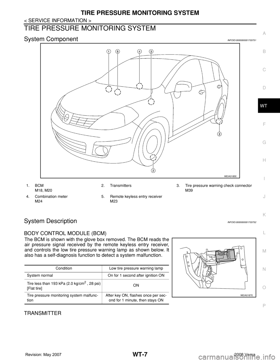
System ComponentINFOID:0000000001703751
System DescriptionINFOID:0000000001703752
BODY CONTROL MODULE (BCM)
The BCM is shown with the glove box removed. The BCM reads the
air pressure signal received by the remote keyless entry receiver,
and controls the low tire pressure warning lamp as shown below. It
also has a self-diagnosis function to detect a system malfunction.
TRANSMITTER
WEIA0185E
1. BCM
M18, M202. Transmitters 3. Tire pressure warning check connector
M39
4. Combination meter
M245. Remote keyless entry receiver
M23
Condition Low tire pressure warning lamp
System normal On for 1 second after ignition ON
Tire less than 193 kPa (2.0 kg/cm
2 , 28 psi)
[Flat tire]ON
Tire pressure monitoring system malfunc-
tionAfter key ON, flashes once per sec-
ond for 1 minute, then stays ON
WEIA0187E
Page 2719 of 2771

TROUBLE DIAGNOSES
WT-11
< SERVICE INFORMATION >
C
D
F
G
H
I
J
K
L
MA
B
WT
N
O
P
ID Registration ProcedureINFOID:0000000001703756
ID REGISTRATION WITH TRANSMITTER ACTIVATION TOOL
NOTE:
This procedure must be done after replacement of a low tire pressure warning transmitter or BCM.
New replacement transmitters are provided "asleep" and must first be "woken up" using Transmitter
Activation Tool J-45295 before ID registration can be performed.
1. Connect CONSULT-III.
2. Select “AIR PRESSURE MONITOR” on "SELECT TEST ITEM" screen.
3. Select “WORK SUPPORT” on "SELECT DIAG MODE" screen, and select "ID REGIST".
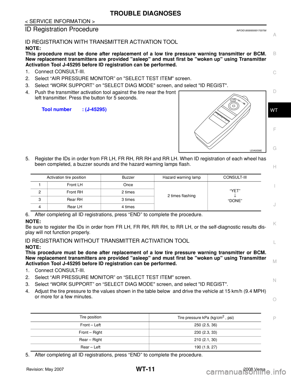
4. Push the transmitter activation tool against the tire near the front
left transmitter. Press the button for 5 seconds.
5. Register the IDs in order from FR LH, FR RH, RR RH and RR LH. When ID registration of each wheel has
been completed, a buzzer sounds and the hazard warning lamps flash.
6. After completing all ID registrations, press “END” to complete the procedure.
NOTE:
Be sure to register the IDs in order from FR LH, FR RH, RR RH, to RR LH, or the self-diagnostic results dis-
play will not function properly.
ID REGISTRATION WITHOUT TRANSMITTER ACTIVATION TOOL
NOTE:
This procedure must be done after replacement of a low tire pressure warning transmitter or BCM.
New replacement transmitters are provided "asleep" and must first be "woken up" using Transmitter
Activation Tool J-45295 before ID registration can be performed.
1. Connect CONSULT-III.
2. Select “AIR PRESSURE MONITOR” on “SELECT TEST ITEM" screen.
3. Select “WORK SUPPORT” on “SELECT DIAG MODE" screen, and select "ID REGIST".
4. Adjust the tire pressure to the values shown in the table below and drive the vehicle at 15 km/h (9.4 MPH)
or more for a few minutes.
5. After completing all ID registrations, press “END” to complete the procedure.Tool number : (J-45295)
LEIA0036E
Activation tire position Buzzer Hazard warning lamp CONSULT-III
1 Front LH Once
2 times flashing“YET”
↓
“DONE” 2 Front RH 2 times
3 Rear RH 3 times
4 Rear LH 4 times
Tire position
Tire pressure kPa (kg/cm2 , psi)
Front – Left 250 (2.5, 36)
Front – Right 230 (2.3, 33)
Rear – Right 210 (2.1, 30)
Rear – Left 190 (1.9, 27)
Page 2720 of 2771

WT-12
< SERVICE INFORMATION >
TROUBLE DIAGNOSES
6. Inflate all tires to proper pressure. Refer to WT-25, "Tire" .
Transmitter Wake Up OperationINFOID:0000000001703757
NOTE:
This procedure must be done after replacement of a low tire pressure warning transmitter or BCM.
New replacement transmitters are provided "asleep" and must first be "woken up" using Transmitter
Activation Tool J-45295 before ID registration can be performed.
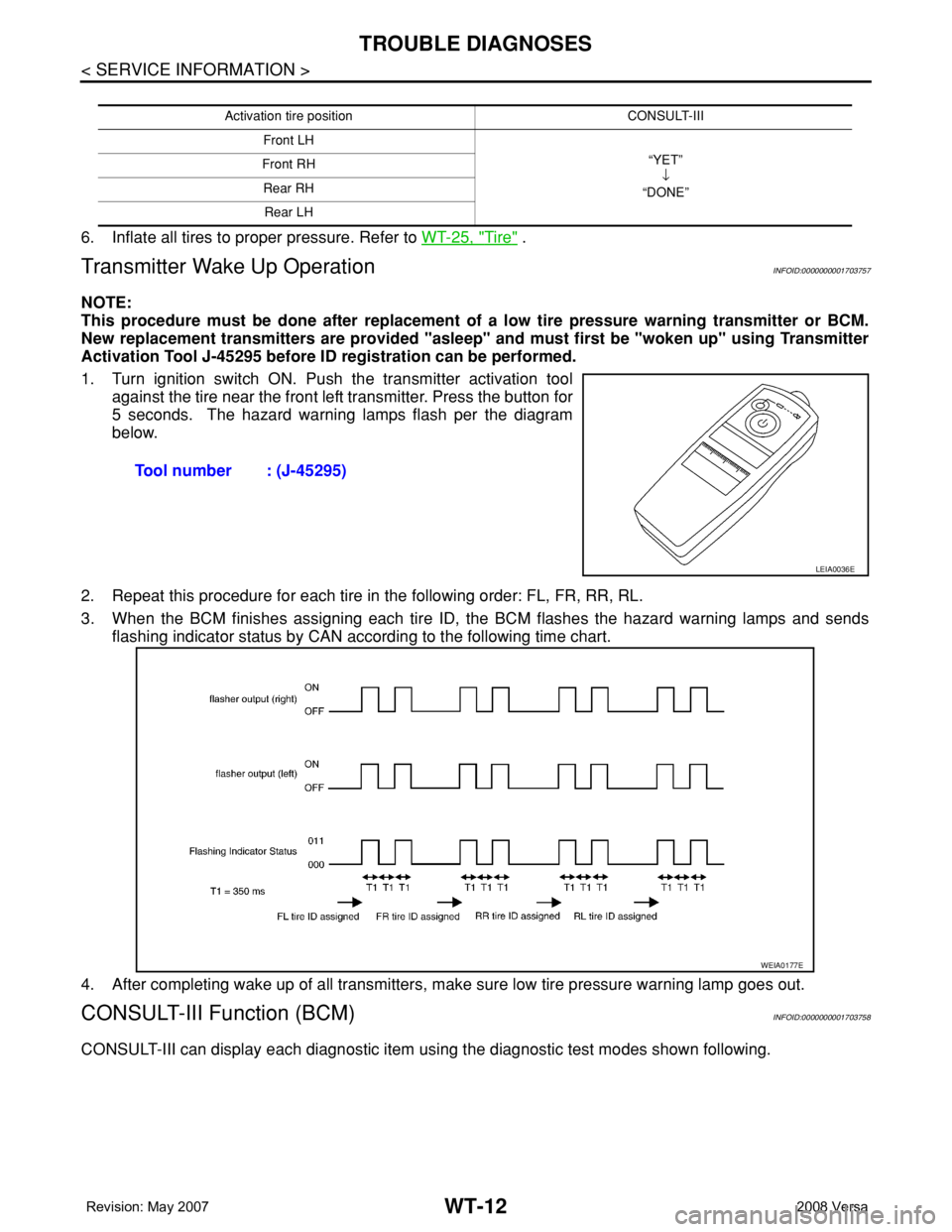
1. Turn ignition switch ON. Push the transmitter activation tool
against the tire near the front left transmitter. Press the button for
5 seconds. The hazard warning lamps flash per the diagram
below.
2. Repeat this procedure for each tire in the following order: FL, FR, RR, RL.
3. When the BCM finishes assigning each tire ID, the BCM flashes the hazard warning lamps and sends
flashing indicator status by CAN according to the following time chart.
4. After completing wake up of all transmitters, make sure low tire pressure warning lamp goes out.
CONSULT-III Function (BCM)INFOID:0000000001703758
CONSULT-III can display each diagnostic item using the diagnostic test modes shown following.
Activation tire position CONSULT-III
Front LH
“YET”
↓
“DONE” Front RH
Rear RH
Rear LH
Tool number : (J-45295)
LEIA0036E
WEIA0177E
Page 2722 of 2771

WT-14
< SERVICE INFORMATION >
TROUBLE DIAGNOSES
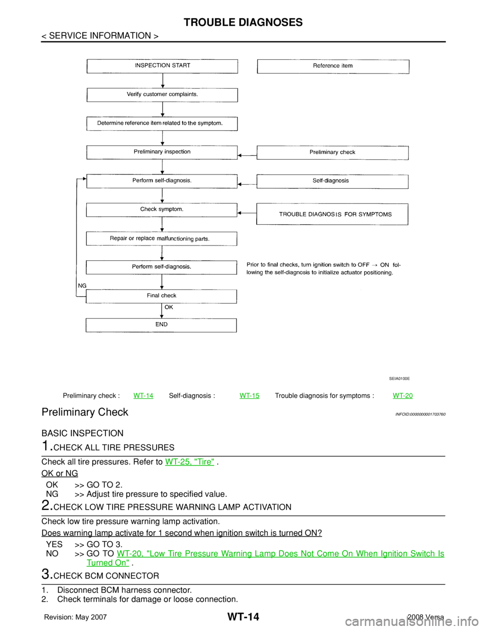
Preliminary Check
INFOID:0000000001703760
BASIC INSPECTION
1.CHECK ALL TIRE PRESSURES
Check all tire pressures. Refer to WT-25, "
Tire" .
OK or NG
OK >> GO TO 2.
NG >> Adjust tire pressure to specified value.
2.CHECK LOW TIRE PRESSURE WARNING LAMP ACTIVATION
Check low tire pressure warning lamp activation.
Does warning lamp activate for 1 second when ignition switch is turned ON?
YES >> GO TO 3.
NO >> GO TO WT-20, "
Low Tire Pressure Warning Lamp Does Not Come On When Ignition Switch Is
Turned On" .
3.CHECK BCM CONNECTOR
1. Disconnect BCM harness connector.
2. Check terminals for damage or loose connection.
Preliminary check :WT-14Self-diagnosis :WT-15Trouble diagnosis for symptoms :WT-20
SEIA0100E
Page 2723 of 2771

TROUBLE DIAGNOSES
WT-15
< SERVICE INFORMATION >
C
D
F
G
H
I
J
K
L
MA
B
WT
N
O
P
3. Reconnect harness connector.
OK or NG
OK >> GO TO 4.
NG >> Repair or replace damaged parts.
4.CHECK TRANSMITTER ACTIVATION TOOL
Check transmitter activation tool battery.
OK or NG
OK >> Carry out self-diagnosis.
NG >> Replace battery in transmitter activation tool.
Self-DiagnosisINFOID:0000000001703761
DESCRIPTION
During driving, the tire pressure monitoring system receives the signal transmitted from the transmitter
installed in each wheel, and turns on the low tire pressure warning lamp when the tire pressure becomes low.
The control unit (BCM) for this system has pressure judgement and self-diagnosis functions.
FUNCTION
When the tire pressure monitoring system detects low inflation pressure or an internal malfunction, the low tire
pressure warning lamp in the combination meter comes on. The malfunction location is indicated by the low
tire pressure warning lamp flashing and the buzzer sounding.
CONSULT-III Application to Tire Pressure Monitoring System
× : Applicable
– : Not applicable
Self-Diagnostic Results Mode
ITEM SELF-DIAGNOSTIC RESULTS DATA MONITOR
Front - Left transmitter××
Front - Right transmitter××
Rear - Left transmitter××
Rear - Right transmitter××
Warning lamp —×
Vehicle speed××
Buzzer (in combination meter) —×
CAN Communication××
Diagnostic item Diagnostic item is detected when ···Reference
page
FLAT - TIRE - FL [C1704]
FLAT - TIRE - FR [C1705]
FLAT - TIRE - RR [C1706]
FLAT - TIRE - RL [C1707]FL tire pressure 193 kPa (2.0 kg/cm
2 , 28 psi) or less
FR tire pressure 193 kPa (2.0 kg/cm2 , 28 psi) or less
RR tire pressure 193 kPa (2.0 kg/cm2 , 28 psi) or less
RL tire pressure 193 kPa (2.0 kg/cm2 , 28 psi) or less—
[NO-DATA] - FL [C1708]
[NO-DATA] - FR [C1709]
[NO-DATA] - RR [C1710]
[NO-DATA] - RL [C1711]Data from FL transmitter cannot be received.
Data from FR transmitter cannot be received.
Data from RR transmitter cannot be received.
Data from RL transmitter cannot be received.WT-18
[CHECKSUM- ERR] - FL [C1712]
[CHECKSUM- ERR] - FR [C1713]
[CHECKSUM- ERR] - RR [C1714]
[CHECKSUM- ERR] - RL [C1715]Checksum data from FL transmitter is malfunctioning.
Checksum data from FR transmitter is malfunctioning.
Checksum data from RR transmitter is malfunctioning.
Checksum data from RL transmitter is malfunctioning.WT-18
[PRESSDATA- ERR] - FL [C1716]
[PRESSDATA- ERR] - FR [C1717]
[PRESSDATA- ERR] - RR [C1718]
[PRESSDATA- ERR] - RL [C1719]Air pressure data from FL transmitter is malfunctioning.
Air pressure data from FR transmitter is malfunctioning.
Air pressure data from RR transmitter is malfunctioning.
Air pressure data from RL transmitter is malfunctioning.WT-19
Page 2724 of 2771

WT-16
< SERVICE INFORMATION >
TROUBLE DIAGNOSES
NOTE:
Before performing the self-diagnosis, be sure to register the ID or else the actual malfunction location may be different from that dis-
played on CONSULT-III.
Data Monitor Mode
NOTE:
Before performing the self-diagnosis, be sure to register the ID, or the actual malfunction location may be different from that displayed on
CONSULT-III.
Flash Code/Symptom ChartINFOID:0000000001703762
[CODE- ERR] - FL [C1720]
[CODE- ERR] - FR [C1721]
[CODE- ERR] - RR [C1722]
[CODE- ERR] - RL [C1723]Function code data from FL transmitter is malfunctioning.
Function code data from FR transmitter is malfunctioning.
Function code data from RR transmitter is malfunctioning.
Function code data from RL transmitter is malfunctioning.WT-18
[BATT - VOLT - LOW] - FL [C1724]
[BATT - VOLT - LOW] - FR [C1725]
[BATT - VOLT - LOW] - RR [C1726]
[BATT - VOLT - LOW] - RL [C1727]Battery voltage of FL transmitter drops.
Battery voltage of FR transmitter drops.
Battery voltage of RR transmitter drops.
Battery voltage of RL transmitter drops.WT-18
VHCL_SPEED_SIG_ERR [C1729] Vehicle speed signal is in error.WT-19
Diagnostic item Diagnostic item is detected when ···Reference
page
MONITOR CONDITION SPECIFICATION
VHCL SPEED Drive vehicle. Vehicle speed (km/h or MPH)
AIR PRESS FL
AIR PRESS FR
AIR PRESS RR
AIR PRESS RL• Drive vehicle for a few minutes.
Tire pressure (kPa or psi) or
• Ignition switch ON and activation tool
is transmitting activation signals.
ID REGST FL1
ID REGST FR1
ID REGST RR1
ID REGST RL1
Ignition switch ONRegistration ID: DONE
No registration ID: YET
WARNING LAMPLow tire pressure warning lamp on: ON
Low tire pressure warning lamp off: OFF
BUZZERBuzzer in combination meter on: ON
Buzzer in combination meter off: OFF
Flash Code or Symptom Malfunction partReference
page
15
16
17
18FL tire pressure drops to 193 kPa (2.0 kg/cm
2 , 28 psi) or less
FR tire pressure drops to 193 kPa (2.0 kg/cm2 , 28 psi) or less
RR tire pressure drops to 193 kPa (2.0 kg/cm2 , 28 psi) or less
RL tire pressure drops to 193 kPa (2.0 kg/cm2 , 28 psi) or less—
21
22
23
24Transmitter no data (FL)
Transmitter no data (FR)
Transmitter no data (RR)
Transmitter no data (RL)WT-18
31
32
33
34Transmitter checksum error (FL)
Transmitter checksum error (FR)
Transmitter checksum error (RR)
Transmitter checksum error (RL)WT-18
35
36
37
38Transmitter pressure data error (FL)
Transmitter pressure data error (FR)
Transmitter pressure data error (RR)
Transmitter pressure data error (RL)WT-19