2008 NISSAN LATIO key
[x] Cancel search: keyPage 2228 of 2771

INTERIOR ROOM LAMP
LT-91
< SERVICE INFORMATION >
C
D
E
F
G
H
I
J
L
MA
B
LT
N
O
P
• to map lamp terminal 1
Power is supplied
• through BCM terminal 56
• to map lamp terminal 4.
When interior room lamp switch is ON, ground is supplied
• to interior room lamp terminal 1
• through map lamp (with map lamp) terminal 7
• through map lamp (with map lamp) terminal 1
• through grounds M57 and M61.
Power is supplied
• through BCM terminal 56
• through map lamp (with map lamp) terminal 4
• through map lamp (with map lamp) terminal 6
• to room lamp terminal 3.
INTERIOR ROOM LAMP TIMER OPERATION
Without Intelligent Key System
When room lamp switch is in DOOR position, and when all conditions below are met, BCM performs timer
control (maximum 30 seconds) for room lamp ON/OFF.
In addition, when the interior room lamp turns ON or OFF there is gradual brightening or dimming over 1 sec-
ond.
Power is supplied
• through 10A fuse [No. 14, located in fuse block (J/B)]
• to key switch and key lock solenoid terminal 2.
When the key is removed from ignition key cylinder (key switch OFF), power will not be supplied to BCM termi-
nal 37.
When front door key cylinder switch LH is unlocked, ground is supplied
• to BCM terminal 7
• through front door key cylinder switch LH terminal 3
• through front door key cylinder switch LH terminal 2
• through grounds M57 and M61.
At the time that front door LH is opened, BCM detects that front door LH is unlocked. It determines that interior
room lamp timer operation condition is met, and turns the room lamp ON for 30 seconds.
When key is in ignition key cylinder (key switch ON),
Power is supplied
• through key switch and key lock solenoid terminal 1
• to BCM terminal 37.
When key is removed from key switch and key lock solenoid (key switch OFF), the power supply to BCM ter-
minal 37 is terminated. BCM detects that key has been removed, determines that interior room lamp timer
conditions are met, and turns the room lamp ON for 30 seconds.
When front door LH opens → closes, and the key is not inserted in the key switch and key lock solenoid (key
switch OFF), voltage at BCM terminal 47 changes between 0V (door open) → 12V (door closed). The BCM
determines that conditions for room lamp operation are met and turns the room lamp ON for 30 seconds.
Interior room lamp timer control is canceled under the following conditions:
• Front door LH is locked (locked front door key cylinder switch LH).
• Front door LH is opened (front door switch LH).
• Ignition switch ON.
With Intelligent Key System
When the room lamp switch is in DOOR position, and when all conditions below are met, BCM performs timer
control (maximum 30 second) for room lamp ON/OFF.
In addition, when interior room lamp turns ON or OFF there is gradual brightening or dimming over 1 second.
Power is supplied
• through 10A fuse (No. 31, located in fuse and fusible link box)
• to key switch and ignition knob switch terminals 2 and 4.
When key is removed from ignition key cylinder (key switch OFF), power will not be supplied to BCM terminal
37.
When the ignition knob switch is released, power will not be supplied to Intelligent Key unit terminal 27.
When front door key cylinder switch LH is unlocked, ground is supplied
• to BCM terminal 7
• through front door key cylinder switch LH terminal 3
Page 2229 of 2771

LT-92
< SERVICE INFORMATION >
INTERIOR ROOM LAMP
• through front door key cylinder switch LH terminal 2
• through grounds M57 and M61.
At the time the front door LH is opened, the BCM detects the front door LH is unlocked. It determines that the
interior room lamp timer operation conditions are met, and interior room lamp ON for 30 seconds.
When the key is in ignition key cylinder (key switch ON), or ignition knob switch is pushed, power is supplied
• through key switch and ignition knob switch terminal 1
• to BCM terminal 37, or
• through key switch and ignition knob switch terminal 3
• to Intelligent Key unit terminal 27.
When the key is removed from key switch (key switch OFF), power supply to BCM terminal 37 is terminated.
When the ignition knob switch is released, power supply to intelligent key unit is terminated. The BCM detects
that the key has been removed, determines that interior room lamp timer conditions are met, and turns room
lamp ON for 30 seconds.
When the front door LH opens → closes, and key is not inserted in key switch (or ignition knob switch is
released), BCM terminal 47 changes between 0V (door open) → 12V (door closed). BCM determines that
conditions for room lamp operation are met, and turns room lamp ON for 30 seconds.
Interior room lamp timer control is canceled under the following conditions:
• Front door LH is locked (with keyfob or front door key cylinder switch LH).
• Front door LH is opened (front door switch LH).
• Ignition switch ON.
INTERIOR LAMP BATTERY SAVER CONTROL
If an interior room lamp is left ON, it will not be turned OFF even when door is closed.
BCM turns off interior lamp automatically to save battery 30 minutes after ignition switch is turned off.
After lamps are turned OFF by the battery saver system, the lamps illuminate again when
• front door key cylinder switch LH is locked or unlocked
• door is opened or closed
• key is removed from ignition key cylinder or inserted in ignition key cylinder, or the ignition knob switch is
pushed or released.
Interior lamp battery saver control time period can be changed by the function setting of CONSULT-III.
Page 2236 of 2771

INTERIOR ROOM LAMP
LT-99
< SERVICE INFORMATION >
C
D
E
F
G
H
I
J
L
MA
B
LT
N
O
P
3. Perform the preliminary check. Refer to LT-99, "Preliminary Check" .
4. Check symptom and repair or replace the cause of the malfunction.
5. Does the interior room lamp operate normally? If YES, GO TO 6. If NO, GO TO 4.
6. Inspection End
Preliminary CheckINFOID:0000000001704474
CHECK POWER SUPPLY AND GROUND CIRCUIT FOR BCM
Refer to BCS-15, "BCM Power Supply and Ground Circuit Inspection" .
CHECK POWER SUPPLY AND GROUND CIRCUIT FOR IPDM E/R
Refer to LT- 11 , "Preliminary Check" .
CONSULT-III Function (BCM)INFOID:0000000001704475
Refer to LT- 11 , "CONSULT-III Function (BCM)".
WORK SUPPORT
Display Item List
Reference between “MODE” and “TIME” for “TURN ON/OFF”
DATA MONITOR
Display Item List
Item Description CONSULT-III
SET I/L D−UNLCK INTCONThe 30 second operating function of the interior room lamps can be selected
when the front door LH is released (unlocked). ON/OFF
ROOM LAMP ON TIME SETThe time in order to escalate illumination can be adjusted when interior room
lamps are turned on.MODE 1 – 7
ROOM LAMP OFF TIME SETThe time in order to diminish illumination can be adjusted when interior room
lamps are turned off.MODE 1 – 7
MODE 123 4 5 6 7
Time (sec.) 0.5 1 2 3 4 5 0
Monitor item Contents
IGN ON SW “ON/OFF” Displays “IGN position (ON)/OFF, ACC position (OFF)” judged from ignition switch signal.
KEY ON SW “ON/OFF” Displays “Key inserted (ON)/key removed (OFF)” status judged from key switch signal.
DOOR SW - DR “ON/OFF”Displays status of front door LH as judged from front door switch LH signal. (Door is open:
ON/Door is closed: OFF)
DOOR SW - AS “ON/OFF”Displays “Door open (ON)/Door closed (OFF)” status, determined from front door switch
RH signal.
DOOR SW - RR “ON/OFF”Displays “Door open (ON)/Door closed (OFF)” status, determined from rear door switch
RH signal.
DOOR SW - RL “ON/OFF”Displays “Door open (ON)/Door closed (OFF) ” status, determined from rear door switch
LH signal.
TRUNK “ON/OFF”Displays "Back door/Trunk open (ON)/closed (OFF)" status, determined from the back
door switch (hatchback) or the trunk lamp switch (sedan).
LOCK STATUS “ON/OFF”Display status (door is locked: ON/door is unlocked: OFF) of front door lock actuator LH
(unlock sensor) judged from the front door lock actuator LH (unlock sensor) signal.
CDL LOCK SW “ON/OFF”Displays “Door locked (ON)/Door unlocked (OFF) status, determined from locking detec-
tion switch in the front door LH.
CDL UNLOCK SW “ON/OFF”Displays “Door unlocked (OFF)” status, determined from locking detection switch in front
door RH.
Page 2237 of 2771
LT-100
< SERVICE INFORMATION >
INTERIOR ROOM LAMP
NOTE:
Vehicles without intelligent key system display this item, but cannot be monitored.
ACTIVE TEST
Display Item List
WORK SUPPORT
Display Item List
Interior Room Lamp Control Does Not Operate (With Map Lamp)INFOID:0000000001704476
1.CHECK EACH SWITCH
Select "BCM" on CONSULT-III. With "INT LAMP" data monitor, make sure switches listed in display item list
turn ON-OFF linked with switch operation. Refer to LT-99, "
CONSULT-III Function (BCM)" for switches and
their functions.
OK or NG
OK >> GO TO 2.
NG >> Inspect malfunctioning switch system.
2.ACTIVE TEST
1. Select “BCM” on CONSULT-III. Select “INT LAMP" active test.
2. When room lamp switch is in DOOR position, make sure room lamp operates.
OK or NG
OK >> Replace BCM. Refer to BCS-18, "Removal and Installation of BCM" .
NG >> GO TO 3.
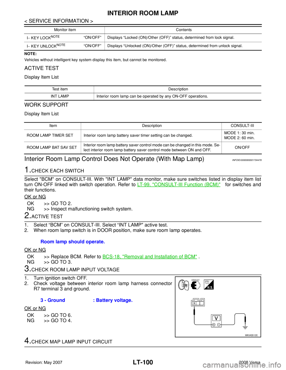
3.CHECK ROOM LAMP INPUT VOLTAGE
1. Turn ignition switch OFF.
2. Check voltage between interior room lamp harness connector
R7 terminal 3 and ground.
OK or NG
OK >> GO TO 6.
NG >> GO TO 4.
4.CHECK MAP LAMP INPUT CIRCUIT
I− KEY LOCKNOTE“ON/OFF” Displays “Locked (ON)/Other (OFF)” status, determined from lock signal.
I− KEY UNLOCK
NOTE“ON/OFF” Displays “Unlocked (ON)/Other (OFF)” status, determined from unlock signal. Monitor item Contents
Test item Description
INT LAMP Interior room lamp can be operated by any ON-OFF operations.
Item Description CONSULT-III
ROOM LAMP TIMER SET Interior room lamp battery saver timer setting can be changed.MODE 1: 30 min.
MODE 2: 60 min.
ROOM LAMP BAT SAV SETInterior room lamp battery saver control mode can be changed in this mode. Se-
lect interior room lamp battery saver control mode between ON and OFF.ON/OFF
Room lamp should operate.
3 - Ground : Battery voltage.
WKIA5512E
Page 2297 of 2771
DESCRIPTION
MT-9
< SERVICE INFORMATION >
D
E
F
G
H
I
J
K
L
MA
B
MT
N
O
P
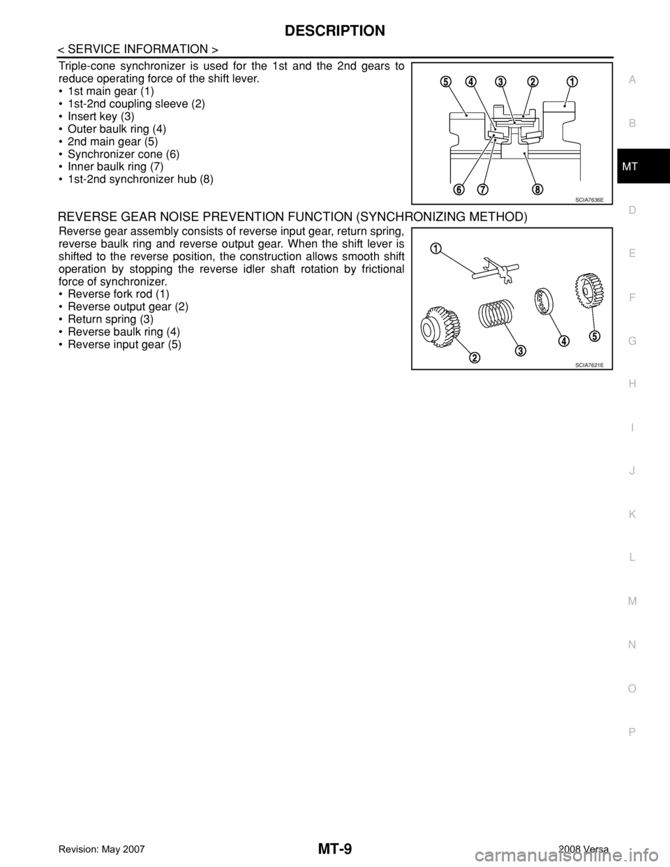
Triple-cone synchronizer is used for the 1st and the 2nd gears to
reduce operating force of the shift lever.
• 1st main gear (1)
• 1st-2nd coupling sleeve (2)
• Insert key (3)
• Outer baulk ring (4)
• 2nd main gear (5)
• Synchronizer cone (6)
• Inner baulk ring (7)
• 1st-2nd synchronizer hub (8)
REVERSE GEAR NOISE PREVENTION FUNCTION (SYNCHRONIZING METHOD)
Reverse gear assembly consists of reverse input gear, return spring,
reverse baulk ring and reverse output gear. When the shift lever is
shifted to the reverse position, the construction allows smooth shift
operation by stopping the reverse idler shaft rotation by frictional
force of synchronizer.
• Reverse fork rod (1)
• Reverse output gear (2)
• Return spring (3)
• Reverse baulk ring (4)
• Reverse input gear (5)
SCIA7636E
SCIA7621E
Page 2307 of 2771
TRANSAXLE ASSEMBLY
MT-19
< SERVICE INFORMATION >
D
E
F
G
H
I
J
K
L
MA
B
MT
N
O
P
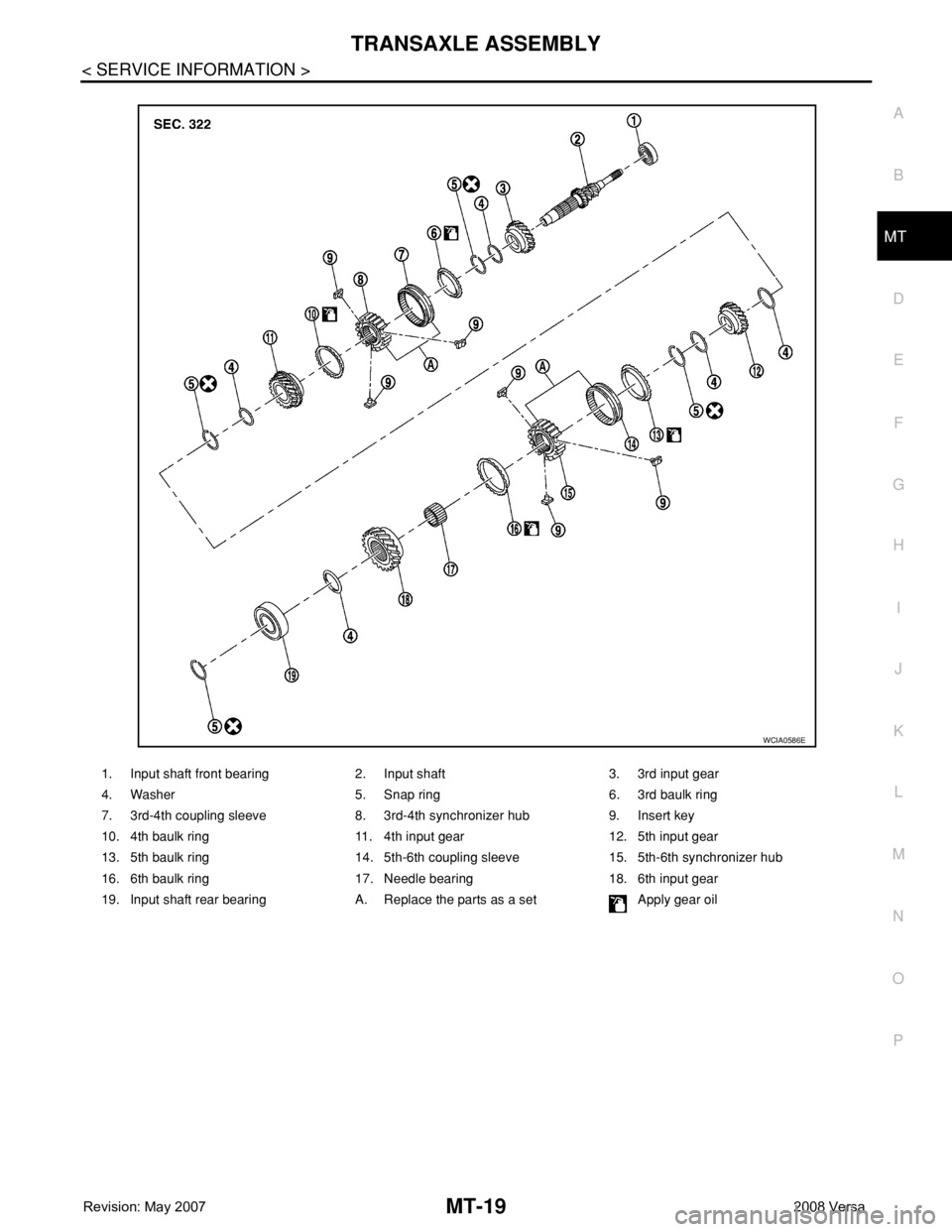
1. Input shaft front bearing 2. Input shaft 3. 3rd input gear
4. Washer 5. Snap ring 6. 3rd baulk ring
7. 3rd-4th coupling sleeve 8. 3rd-4th synchronizer hub 9. Insert key
10. 4th baulk ring 11. 4th input gear 12. 5th input gear
13. 5th baulk ring 14. 5th-6th coupling sleeve 15. 5th-6th synchronizer hub
16. 6th baulk ring 17. Needle bearing 18. 6th input gear
19. Input shaft rear bearing A. Replace the parts as a set Apply gear oil
WCIA0586E
Page 2308 of 2771
MT-20
< SERVICE INFORMATION >
TRANSAXLE ASSEMBLY
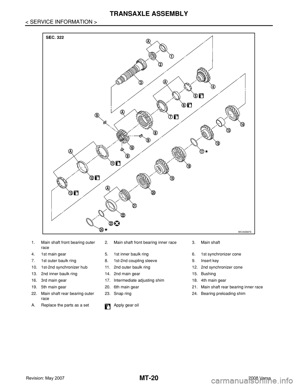
1. Main shaft front bearing outer
race2. Main shaft front bearing inner race 3. Main shaft
4. 1st main gear 5. 1st inner baulk ring 6. 1st synchronizer cone
7. 1st outer baulk ring 8. 1st-2nd coupling sleeve 9. Insert key
10. 1st-2nd synchronizer hub 11. 2nd outer baulk ring 12. 2nd synchronizer cone
13. 2nd inner baulk ring 14. 2nd main gear 15. Bushing
16. 3rd main gear 17. Intermediate adjusting shim 18. 4th main gear
19. 5th main gear 20. 6th main gear 21. Main shaft rear bearing inner race
22. Main shaft rear bearing outer
race23. Snap ring 24. Bearing preloading shim
A. Replace the parts as a set Apply gear oil
WCIA0587E
Page 2325 of 2771
INPUT SHAFT AND GEARS
MT-37
< SERVICE INFORMATION >
D
E
F
G
H
I
J
K
L
MA
B
MT
N
O
P
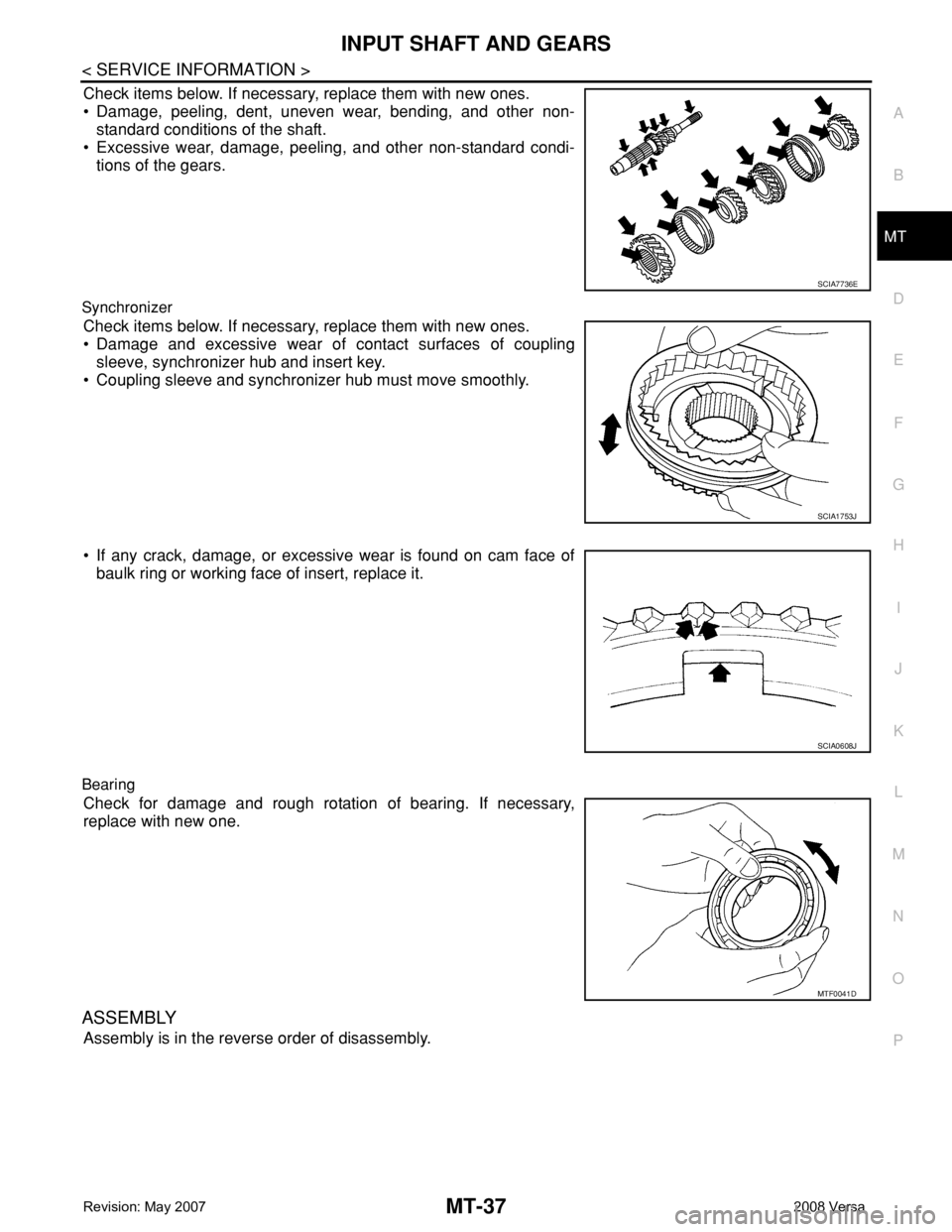
Check items below. If necessary, replace them with new ones.
• Damage, peeling, dent, uneven wear, bending, and other non-
standard conditions of the shaft.
• Excessive wear, damage, peeling, and other non-standard condi-
tions of the gears.
Synchronizer
Check items below. If necessary, replace them with new ones.
• Damage and excessive wear of contact surfaces of coupling
sleeve, synchronizer hub and insert key.
• Coupling sleeve and synchronizer hub must move smoothly.
• If any crack, damage, or excessive wear is found on cam face of
baulk ring or working face of insert, replace it.
Bearing
Check for damage and rough rotation of bearing. If necessary,
replace with new one.
ASSEMBLY
Assembly is in the reverse order of disassembly.
SCIA7736E
SCIA1753J
SCIA0608J
MTF0041D