2008 NISSAN LATIO tire pressure
[x] Cancel search: tire pressurePage 2272 of 2771

MA-12
< SERVICE INFORMATION >
ENGINE MAINTENANCE
ENGINE MAINTENANCE
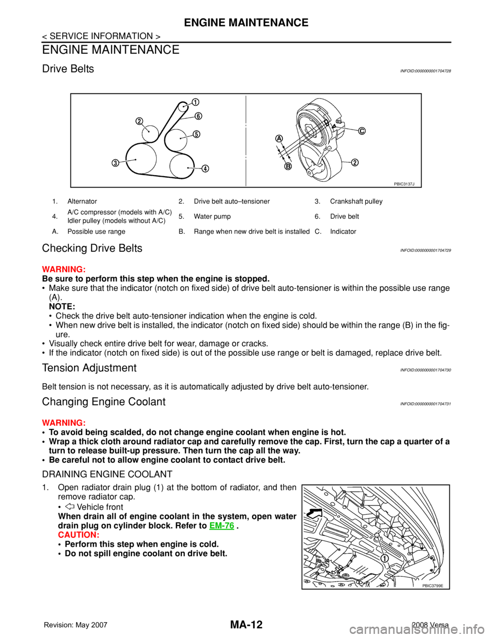
Drive BeltsINFOID:0000000001704728
Checking Drive BeltsINFOID:0000000001704729
WARNING:
Be sure to perform this step when the engine is stopped.
• Make sure that the indicator (notch on fixed side) of drive belt auto-tensioner is within the possible use range
(A).
NOTE:
• Check the drive belt auto-tensioner indication when the engine is cold.
• When new drive belt is installed, the indicator (notch on fixed side) should be within the range (B) in the fig-
ure.
• Visually check entire drive belt for wear, damage or cracks.
• If the indicator (notch on fixed side) is out of the possible use range or belt is damaged, replace drive belt.
Tension AdjustmentINFOID:0000000001704730
Belt tension is not necessary, as it is automatically adjusted by drive belt auto-tensioner.
Changing Engine CoolantINFOID:0000000001704731
WARNING:
• To avoid being scalded, do not change engine coolant when engine is hot.
• Wrap a thick cloth around radiator cap and carefully remove the cap. First, turn the cap a quarter of a
turn to release built-up pressure. Then turn the cap all the way.
• Be careful not to allow engine coolant to contact drive belt.
DRAINING ENGINE COOLANT
1. Open radiator drain plug (1) at the bottom of radiator, and then
remove radiator cap.
• Vehicle front
When drain all of engine coolant in the system, open water
drain plug on cylinder block. Refer to EM-76
.
CAUTION:
• Perform this step when engine is cold.
• Do not spill engine coolant on drive belt.
1. Alternator 2. Drive belt auto–tensioner 3. Crankshaft pulley
4.A/C compressor (models with A/C)
Idler pulley (models without A/C)5. Water pump 6. Drive belt
A. Possible use range B. Range when new drive belt is installed C. Indicator
PBIC3137J
PBIC3799E
Page 2417 of 2771

REFRIGERANT LINES
MTC-79
< SERVICE INFORMATION >
C
D
E
F
G
H
I
K
L
MA
B
MTC
N
O
P
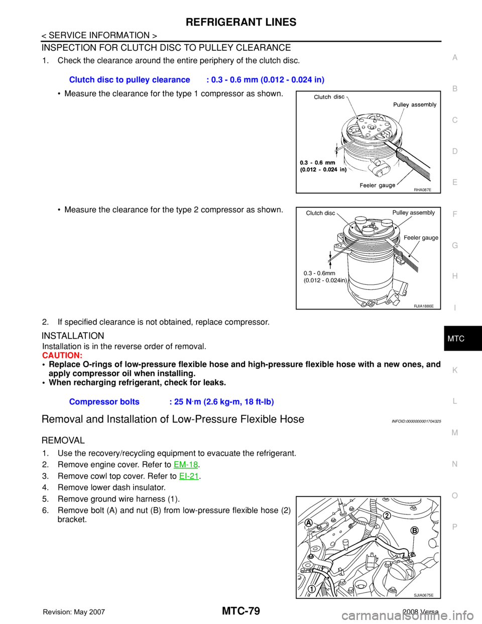
INSPECTION FOR CLUTCH DISC TO PULLEY CLEARANCE
1. Check the clearance around the entire periphery of the clutch disc.
• Measure the clearance for the type 1 compressor as shown.
• Measure the clearance for the type 2 compressor as shown.
2. If specified clearance is not obtained, replace compressor.
INSTALLATION
Installation is in the reverse order of removal.
CAUTION:
• Replace O-rings of low-pressure flexible hose and high-pressure flexible hose with a new ones, and
apply compressor oil when installing.
• When recharging refrigerant, check for leaks.
Removal and Installation of Low-Pressure Flexible HoseINFOID:0000000001704325
REMOVAL
1. Use the recovery/recycling equipment to evacuate the refrigerant.
2. Remove engine cover. Refer to EM-18
.
3. Remove cowl top cover. Refer to EI-21
.
4. Remove lower dash insulator.
5. Remove ground wire harness (1).
6. Remove bolt (A) and nut (B) from low-pressure flexible hose (2)
bracket.Clutch disc to pulley clearance : 0.3 - 0.6 mm (0.012 - 0.024 in)
RHA087E
RJIA1886E
Compressor bolts : 25 N·m (2.6 kg-m, 18 ft-lb)
SJIA0675E
Page 2472 of 2771

HARNESS
PG-39
< SERVICE INFORMATION >
C
D
E
F
G
H
I
J
L
MA
B
PG
N
O
P
C2 M6 W/4 : Steering lock solenoid E2 M52 W/40 : Intelligent key unit
B3 M7 W/16 : Door mirror remote control switch B2 M53 W/16 : EPS control unit
A3 M8 W/16 : To D2 B3 M54 B/2 : EPS control unit
A3 M9 W/16 : To D1 C3 M55† W/4: Hazard switch (hatchback early
production)
E2 M10 GR/2 : Instrument panel antenna D2 M55†† W/4: Hazard switch (hatchback late production
or sedan)
G3 M11 W/4 : To B106 B2 M57 — : Body ground
G4 M12 W/16 : To B101 F2 M59 W/2 : Glove box lamp
G3 M13 W/24 : To B102 C1 M60 L/2 : EPS control unit
G3 M14 W/24 : To B120 F1 M61 — : Body ground
B4 M15 W/16 : To B23 E2 M62 W/2 : Front blower motor
B4 M16 W/24 : To B24 C1 M63 W/4 : Torque sensor
D5 M17 B/1 : Parking brake switch A2 M69 SMJ : To E7
F2 M18 W/40 : BCM (body control module) B2 M73 GR/6: Key switch and ignition knob switch (With
intelligent key)
F2 M19 W/15 : BCM (body control module) G3 M74 W/12 : To D102
F3 M20 B/15 : BCM (body control module) G3 M75 W/12 : To D101
C2 M21 W/4 : NATS antenna amp. F2 M77 Y/4 : Front passenger air bag module
B3 M22 W/16 : Data link connector A2 M78 B/2 : To E11
E3 M23 W/4 : Remote keyless entry receiver B1 M79 — : Body ground
C1 M24 W/40 : Combination meter D3 M150 W/4 : To M32
C3 M25 /2 : Diode-1 C3 M151 W/4 : Front blower motor resistor
B2 M26 W/6 : Ignition switch
C2 M27 GR/6 : Key switch and key lock solenoid
C2 M28 W/16 : Combination switch
C3 M29 Y/6 : Combination switch (spiral cable)
C3 M30 GR/8 : Combination switch (spiral cable)
E3 M32 W/4 : To M150
D2 M33 B/15 : Front air control
D4 M35 Y/28 : Air bag diagnosis sensor unit
D2 M36† W/3: Front passenger air bag OFF indicator
(hatchback early production)
C3 M36†† W/3: Front passenger air bag OFF indicator
(hatchback late production or sedan)
D4 M38 W/6 : A/T device
D4 M38 W/6 : CVT device (without intelligent key)
D4 M38 W/8 : CVT device (with intelligent key)
B3 M39 W/2 : Tire pressure warning check connector
D2 M41 W/2 : Defrost A/C switch
D3 M42 W/3 : Thermo control amp. (without CVT)
D2 M43 W/20 : Audio unit
Page 2493 of 2771

PG-60
< SERVICE INFORMATION >
HARNESS
SEN/PW EC Sensor Power Supply
SESCVT CVT Secondary Pressure Sensor Solenoid Valve
SHIFT AT A/T Shift Lock System
SHIFT CVT CVT Shift Lock System
SROOF RF Sunroof
SRS SRS Supplemental Restraint System
SSV/A AT Shift Solenoid Valve A
SSV/B AT Shift Solenoid Valve B
START SC Starting System
STM CVT Step Motor
STSIG CVT Start Signal Circuit
STOP/L LT Stop Lamp
TCV AT Torque Converter Clutch Solenoid Valve
TCV CVT Torque Converter Clutch Solenoid Valve
T/LID BL Trunk Lid Opener
T/WARN WT Low Tire Pressure Warning System
TAIL/L LT Parking, License and Tail Lamps
TPS1 EC Throttle Position Sensor
TPS2 EC Throttle Position Sensor
TPS3 EC Throttle Position Sensor
TURN LT Turn Signal and Hazard Warning Lamps
VEHSEC BL Vehicle Security (Theft Warning) System
VENT/V EC EVAP Canister Vent Control Valve
VSSA/T AT Vehicle Speed Sensor A/T (Revolution Sensor)
VSSMTR AT Vehicle Speed Sensor MTR
WARN DI Warning Lamps
WINDOW GW Power Window
WIP/R WW Rear Wiper and Washer
WIPER WW Front Wiper and Washer
Page 2564 of 2771

REAR SUSPENSION ASSEMBLY
RSU-5
< SERVICE INFORMATION >
C
D
F
G
H
I
J
K
L
MA
B
RSU
N
O
P
REAR SUSPENSION ASSEMBLY
On-Vehicle Inspection and ServiceINFOID:0000000001703736
Make sure the mounting conditions (looseness, backlash) of each component and component conditions
(wear, damage) are within specifications.
SHOCK ABSORBER INSPECTION
Check shock absorber for oil leakage, damage and replace it if necessary.
Wheel AlignmentInspectionINFOID:0000000001703737
DESCRIPTION
Measure wheel alignment under unladen conditions.
NOTE:
“Unladen conditions” means that fuel, engine coolant, and lubricant are full. Spare tire, jack, hand tools and
mats are in designated positions.
PRELIMINARY
Check the following:
1. Tires for improper air pressure and wear.
2. Road wheels for runout. Refer to WT-5
.
3. Wheel bearing axial end play. Refer to RAX-4, "
On-Vehicle Inspection and Service" .
4. Shock absorber operation.
5. Each mounting part of suspension for looseness and deformation.
6. Rear suspension beam for cracks, deformation, and other damage.
7. Vehicle height (posture).
GENERAL INFORMATION AND RECOMMENDATIONS
1. A Four-Wheel Thrust Alignment should be performed.
• This type of alignment is recommended for any NISSAN vehicle.
• The four-wheel “thrust” process helps ensure that the vehicle is properly aligned and the steering wheel
is centered.
• The alignment machine itself should be capable of accepting any NISSAN vehicle.
• The alignment machine should be checked to ensure that it is level.
2. Make sure the alignment machine is properly calibrated.
• Your alignment machine should be regularly calibrated in order to give correct information.
• Check with the manufacturer of your specific alignment machine for their recommended Service/Cali-
bration Schedule.
THE ALIGNMENT PROCESS
IMPORTANT: Use only the alignment specifications listed in this Service Manual. Refer to RSU-12, "Wheel
Alignment (Unladen*)" .
1. When displaying the alignment settings, many alignment machines use “indicators”: (Green/red, plus or
minus, Go/No Go). Do NOT use these indicators.
• The alignment specifications programmed into your alignment machine that operate these indicators
may not be correct.
• This may result in an ERROR.
2. Some newer alignment machines are equipped with an optional “Rolling Compensation” method to “com-
pensate” the sensors (alignment targets or head units). Do NOT use this “Rolling Compensation”
method.
• Use the “Jacking Compensation” method. After installing the alignment targets or head units, raise the
vehicle and rotate the wheels 1/2 turn both ways.
• See Instructions in the alignment machine you are using for more information.
CAMBER INSPECTION
Page 2681 of 2771

COLLISION DIAGNOSIS
SRS-47
< ON-VEHICLE REPAIR >
C
D
E
F
G
I
J
K
L
MA
B
SRS
N
O
P
For Side and Rollover CollisionINFOID:0000000001703937
Check the SRS components using the following table.
• After the work is completed, perform self-diagnosis to check that no malfunction is detected. Refer to SRS-
18, "SRS Operation Check".
WHEN SRS IS ACTIVATED IN THE SIDE OR ROLLOVER COLLISION
1. Replace the following components:
- Front seat back assembly (on the side on which side air bag is activated)
- Diagnosis sensor unit
- (LH or RH) side air bag (satellite) sensor (on the side on which side air bag is activated)
2. Check the SRS components and the related parts using the following table.
- Replace any SRS components and the related parts showing visible signs of damage (dents, cracks,
deformation).
3. Conduct self-diagnosis using CONSULT-III and “AIR BAG” warning lamp. Refer to SRS-18, "
SRS Opera-
tion Check" for details. Ensure entire SRS operates properly.
WHEN SRS IS NOT ACTIVATED IN THE SIDE OR ROLLOVER COLLISION
1. Check the SRS components and the related parts using the following table.
- If the front seat back assembly is damaged, the front seat back assembly must be replaced.
2. Conduct self-diagnosis using CONSULT-III and “AIR BAG” warning lamp. Refer to SRS-18, "
SRS Opera-
tion Check" for details. Ensure entire SRS operates properly.
SRS INSPECTION (FOR SIDE AND ROLLOVER COLLISION)
Steering wheel 1. Visually check steering wheel for deformities.
2. Check harness (built into steering wheel) and connectors for damage, and terminals for deformities.
3. Install driver air bag module into the steering wheel to check fit and alignment with the wheel.
4. Check steering wheel for excessive free play.
5. If no damage is found, reinstall.
6. If damaged—REPLACE.
Spiral cable If the driver front air
bag has deployed:
REPLACE the spiral
cable.If the driver front air bag has not deployed:
1. Visually check spiral cable and combination switch for damage.
2. Check connectors and protective tape for damage.
3. Check steering wheel for noise, binding or heavy operation.
4. If no damage is found, reinstall.
5. If damaged—REPLACE.
Occupant classifica-
tion system (Passen-
ger seat)1. Remove passenger seat.
2. Check control unit case for dents, cracks of deformities.
3. Check connectors and pressure sensor tube for damage, and terminals for deformities.
4. Check seat frame and cushion pan for dents or deformities.
5. If no damage is found, reinstall seat with new fasteners.
6. If damaged — REPLACE seat cushion assembly with new fasteners.
Harness and connec-
tors1. Check connectors for poor connection, damage, and terminals for deformities.
2. Check harness for binding, chafing, cuts, or deformities.
3. If no damage is found, reinstall the harness and connectors.
4. If damaged—REPLACE the damaged harness. Do not attempt to repair, splice or modify any SRS har-
ness.
Instrument panel If the passenger front
air bag has deployed:
REPLACE the instru-
ment panel assembly.If the passenger front air bag has NOT deployed:
1. Visually check instrument panel for damage.
2. If no damage is found, reinstall the instrument panel.
3. If damaged—REPLACE the instrument panel. Part SRS is activated SRS is NOT activated
Page 2686 of 2771
![NISSAN LATIO 2008 Service Repair Manual PRECAUTIONS
STC-3
< SERVICE INFORMATION >[EPS]
C
D
E
F
H
I
J
K
L
MA
B
STC
N
O
P
• Check any possible causes by interviewing the symptom and it’s condition from the customer if any
malfunction, suc NISSAN LATIO 2008 Service Repair Manual PRECAUTIONS
STC-3
< SERVICE INFORMATION >[EPS]
C
D
E
F
H
I
J
K
L
MA
B
STC
N
O
P
• Check any possible causes by interviewing the symptom and it’s condition from the customer if any
malfunction, suc](/manual-img/5/57360/w960_57360-2685.png)
PRECAUTIONS
STC-3
< SERVICE INFORMATION >[EPS]
C
D
E
F
H
I
J
K
L
MA
B
STC
N
O
P
• Check any possible causes by interviewing the symptom and it’s condition from the customer if any
malfunction, such as EPS warning lamp turns ON, occurs.
• Check if air pressure and size of tires are proper, the specified part is used for the steering wheel,
and control unit is genuine part.
• Check if the connection of steering column assembly and steering gear assembly is proper (there is
not looseness of mounting bolts, damage of rods, boots or sealants, and leakage of grease, etc).
• Check if the wheel alignment is adjusted properly.
• Check if there is any damage or modification to suspension or body resulting in increased weight or
altered ground clearance.
• Check if installation conditions of each link and suspension are proper.
• Check if the battery voltage is proper
• Check connection conditions of each connector are proper.
• Before connecting or disconnecting the EPS control unit har-
ness connector, turn ignition switch “OFF” and disconnect
battery ground cable. Because battery voltage is applied to
EPS control unit even if ignition switch is turned “OFF”.
• When connecting or disconnecting pin connectors into or
from EPS control unit, take care not to damage pin terminals
(bend or break).
When connecting pin connectors, make sure that there are no
bends or breaks on EPS control unit pin terminal.
• Before replacing EPS control unit, perform EPS control unit
input/output signal inspection and make sure whether EPS
control unit functions properly or not. Refer to STC-9, "
EPS
Control Unit Input/Output Signal Reference Value".
SEF289H
SEF291H
SDIA1848E
Page 2709 of 2771

WT-1
SUSPENSION
C
D
F
G
H
I
J
K
L
M
SECTION WT
A
B
WT
N
O
PCONTENTS
ROAD WHEELS & TIRES
SERVICE INFORMATION ............................2
PRECAUTIONS ...................................................2
Precaution for Supplemental Restraint System
(SRS) "AIR BAG" and "SEAT BELT PRE-TEN-
SIONER" ...................................................................
2
PREPARATION ...................................................3
Special Service Tool .................................................3
Commercial Service Tool ..........................................3
NOISE, VIBRATION AND HARSHNESS
(NVH) TROUBLESHOOTING .............................
4
NVH Troubleshooting Chart ......................................4
ROAD WHEEL ....................................................5
Inspection ..................................................................5
ROAD WHEEL TIRE ASSEMBLY ......................6
Balancing Wheels .....................................................6
Rotation .....................................................................6
TIRE PRESSURE MONITORING SYSTEM ........7
System Component ...................................................7
System Description ...................................................7
CAN COMMUNICATION .....................................9
System Description ...................................................9
TROUBLE DIAGNOSES ....................................10
Wiring Diagram- T/WARN - .....................................10
Terminal and Reference Value for BCM .................10
ID Registration Procedure .......................................11
Transmitter Wake Up Operation .............................12
CONSULT-III Function (BCM) .................................12
How to Perform Trouble Diagnosis for Quick and
Accurate Repair .......................................................
13
Preliminary Check ...................................................14
Self-Diagnosis .........................................................15
Flash Code/Symptom Chart ....................................16
TROUBLE DIAGNOSIS FOR SELF-DIAG-
NOSTIC ITEMS .................................................
18
Data from Transmitter Not Being Received .............18
Transmitter Malfunction ...........................................18
Transmitter Pressure Malfunction ............................19
Vehicle Speed Signal ..............................................19
TROUBLE DIAGNOSIS FOR SYMPTOMS ......20
Low Tire Pressure Warning Lamp Does Not Come
On When Ignition Switch Is Turned On ...................
20
Low Tire Pressure Warning Lamp Stays On When
Ignition Switch Is Turned On ...................................
20
Low Tire Pressure Warning Lamp Flashes When
Ignition Switch Is Turned On ...................................
21
Hazard Warning Lamps Flash When Ignition
Switch Is Turned On ................................................
22
ID Registration Cannot Be Completed ....................22
REMOVAL AND INSTALLATION .....................23
Transmitter (Pressure Sensor) ................................23
SERVICE DATA AND SPECIFICATIONS
(SDS) .................................................................
25
Road Wheel .............................................................25
Tire ..........................................................................25