Page 2287 of 2771

CHASSIS AND BODY MAINTENANCE
MA-27
< SERVICE INFORMATION >
C
D
E
F
G
H
I
J
K
MA
B
MA
N
O
P
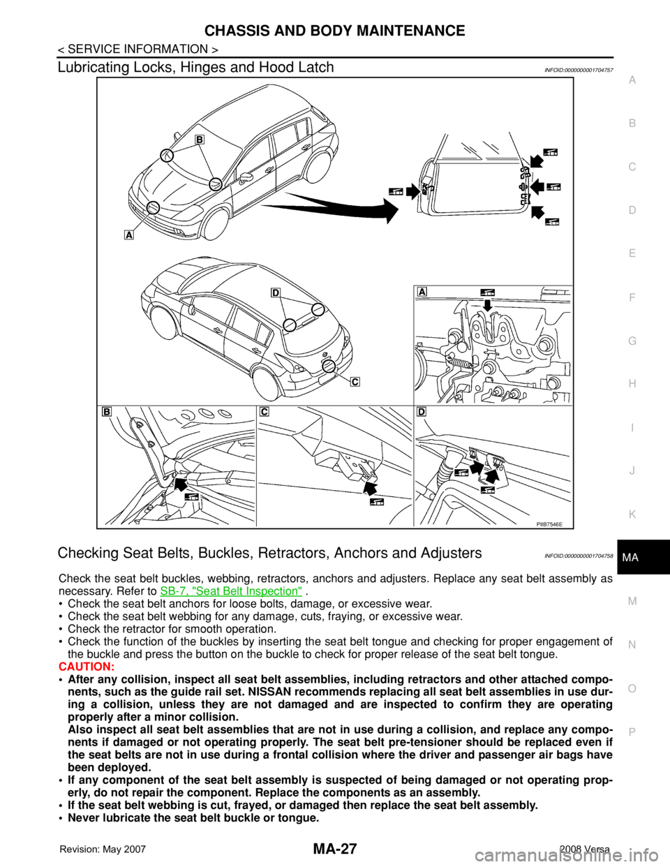
Lubricating Locks, Hinges and Hood LatchINFOID:0000000001704757
Checking Seat Belts, Buckles, Retractors, Anchors and AdjustersINFOID:0000000001704758
Check the seat belt buckles, webbing, retractors, anchors and adjusters. Replace any seat belt assembly as
necessary. Refer to SB-7, "
Seat Belt Inspection" .
• Check the seat belt anchors for loose bolts, damage, or excessive wear.
• Check the seat belt webbing for any damage, cuts, fraying, or excessive wear.
• Check the retractor for smooth operation.
• Check the function of the buckles by inserting the seat belt tongue and checking for proper engagement of
the buckle and press the button on the buckle to check for proper release of the seat belt tongue.
CAUTION:
• After any collision, inspect all seat belt assemblies, including retractors and other attached compo-
nents, such as the guide rail set. NISSAN recommends replacing all seat belt assemblies in use dur-
ing a collision, unless they are not damaged and are inspected to confirm they are operating
properly after a minor collision.
Also inspect all seat belt assemblies that are not in use during a collision, and replace any compo-
nents if damaged or not operating properly. The seat belt pre-tensioner should be replaced even if
the seat belts are not in use during a frontal collision where the driver and passenger air bags have
been deployed.
• If any component of the seat belt assembly is suspected of being damaged or not operating prop-
erly, do not repair the component. Replace the components as an assembly.
• If the seat belt webbing is cut, frayed, or damaged then replace the seat belt assembly.
• Never lubricate the seat belt buckle or tongue.
PIIB7546E
Page 2288 of 2771
MA-28
< SERVICE INFORMATION >
CHASSIS AND BODY MAINTENANCE
• When replacing any seat belt assembly always use a Genuine NISSAN seat belt assembly.
Page 2289 of 2771

MT-1
TRANSMISSION/TRANSAXLE
D
E
F
G
H
I
J
K
L
M
SECTION MT
A
B
MT
N
O
P
CONTENTS
MANUAL TRANSAXLE
SERVICE INFORMATION ............................2
PRECAUTIONS ...................................................2
Precaution for Supplemental Restraint System
(SRS) "AIR BAG" and "SEAT BELT PRE-TEN-
SIONER" ...................................................................
2
Precaution for Procedure without Cowl Top Cover ......2
Precaution .................................................................2
PREPARATION ...................................................3
Special Service Tool .................................................3
Commercial Service Tool ..........................................5
NOISE, VIBRATION AND HARSHNESS
(NVH) TROUBLESHOOTING .............................
7
NVH Troubleshooting Chart ......................................7
DESCRIPTION ....................................................8
Cross-Sectional View ................................................8
M/T OIL ...............................................................10
Changing M/T Oil ....................................................10
Checking M/T Oil .....................................................10
SIDE OIL SEAL ..................................................11
Removal and Installation .........................................11
POSITION SWITCH ............................................12
Checking .................................................................12
CONTROL LINKAGE ........................................13
Component of Control Device and Cable ................13
Removal and Installation .........................................13
AIR BREATHER HOSE ....................................15
Removal and Installation .........................................15
TRANSAXLE ASSEMBLY ................................16
Removal and Installation .........................................16
Disassembly and Assembly .....................................17
INPUT SHAFT AND GEARS ............................35
Disassembly and Assembly .....................................35
MAINSHAFT AND GEARS ...............................39
Disassembly and Assembly .....................................39
REVERSE IDLER SHAFT AND GEARS ..........44
Disassembly and Assembly .....................................44
FINAL DRIVE ....................................................46
Disassembly and Assembly .....................................46
SHIFT CONTROL ..............................................49
Inspection ................................................................49
SERVICE DATA AND SPECIFICATIONS
(SDS) .................................................................
50
General Specification ..............................................50
Page 2290 of 2771

MT-2
< SERVICE INFORMATION >
PRECAUTIONS
SERVICE INFORMATION
PRECAUTIONS
Precaution for Supplemental Restraint System (SRS) "AIR BAG" and "SEAT BELT
PRE-TENSIONER"
INFOID:0000000001703128
The Supplemental Restraint System such as “AIR BAG” and “SEAT BELT PRE-TENSIONER”, used along
with a front seat belt, helps to reduce the risk or severity of injury to the driver and front passenger for certain
types of collision. This system includes seat belt switch inputs and dual stage front air bag modules. The SRS
system uses the seat belt switches to determine the front air bag deployment, and may only deploy one front
air bag, depending on the severity of a collision and whether the front occupants are belted or unbelted.
Information necessary to service the system safely is included in the SRS and SB section of this Service Man-
ual.
WARNING:
• To avoid rendering the SRS inoperative, which could increase the risk of personal injury or death in
the event of a collision which would result in air bag inflation, all maintenance must be performed by
an authorized NISSAN/INFINITI dealer.
• Improper maintenance, including incorrect removal and installation of the SRS, can lead to personal
injury caused by unintentional activation of the system. For removal of Spiral Cable and Air Bag
Module, see the SRS section.
• Do not use electrical test equipment on any circuit related to the SRS unless instructed to in this
Service Manual. SRS wiring harnesses can be identified by yellow and/or orange harnesses or har-
ness connectors.
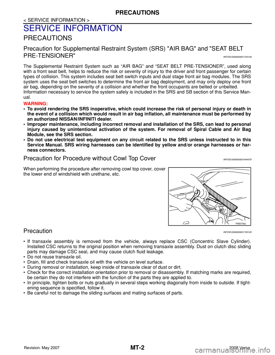
Precaution for Procedure without Cowl Top CoverINFOID:0000000001844076
When performing the procedure after removing cowl top cover, cover
the lower end of windshield with urethane, etc.
PrecautionINFOID:0000000001703129
• If transaxle assembly is removed from the vehicle, always replace CSC (Concentric Slave Cylinder).
Installed CSC returns to the original position when removing transaxle assembly. Dust on clutch disc sliding
parts may damage CSC seal, and may cause clutch fluid leakage.
• Do not reuse transaxle oil.
• Drain, fill and check transaxle oil with the vehicle on level surface.
• During removal or installation, keep inside of transaxle clear of dust or dirt.
• Check for the correct installation orientation prior to removal or disassembly. If matching marks are required,
be certain they do not interfere with the function of the parts they are applied to.
• In principle, tighten bolts or nuts gradually in several steps working diagonally from inside to outside. If tight-
ening sequence is specified, follow it.
• Be careful not to damage the sliding surfaces and mating surfaces of parts.
PIIB3706J
Page 2291 of 2771

PREPARATION
MT-3
< SERVICE INFORMATION >
D
E
F
G
H
I
J
K
L
MA
B
MT
N
O
P
PREPARATION
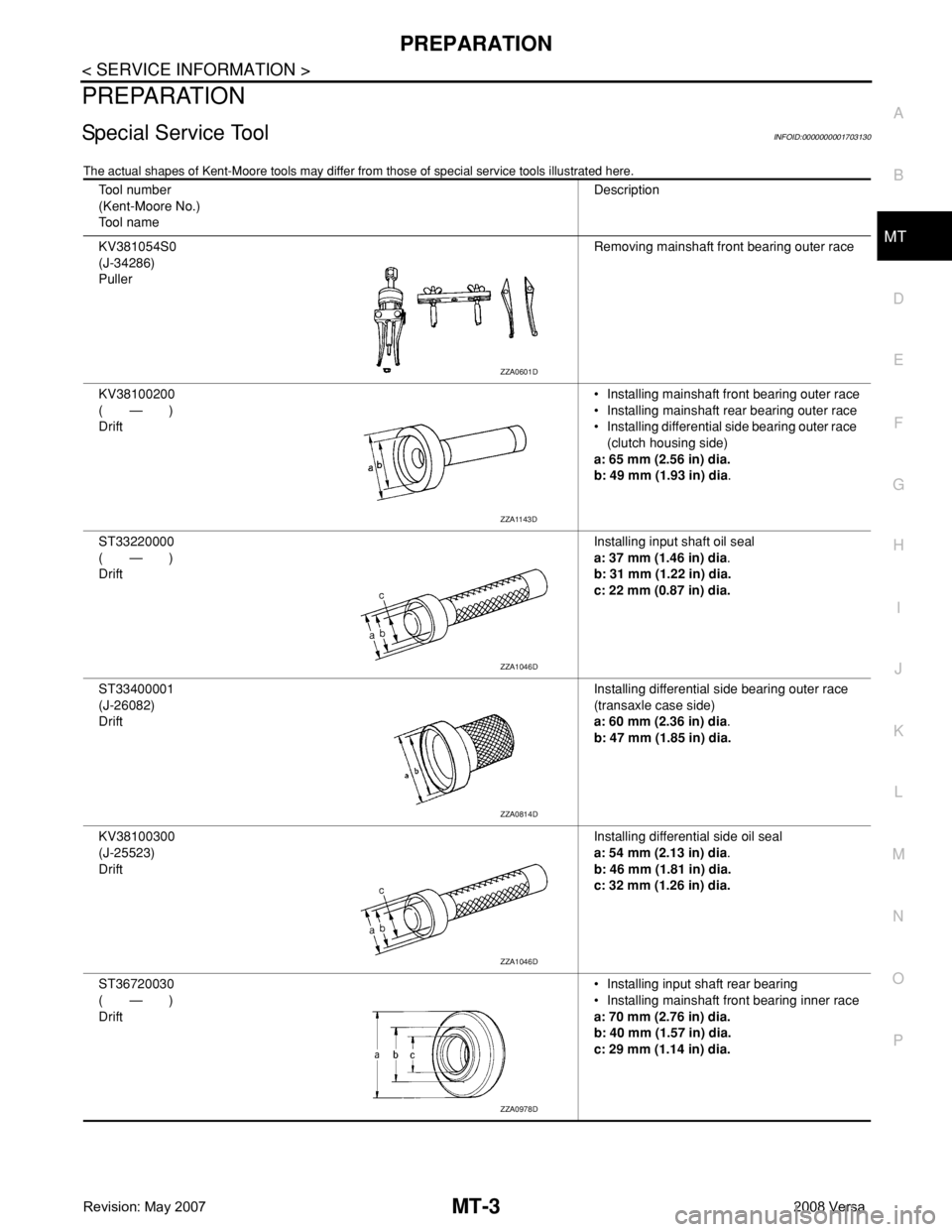
Special Service ToolINFOID:0000000001703130
The actual shapes of Kent-Moore tools may differ from those of special service tools illustrated here.
Tool number
(Kent-Moore No.)
Tool nameDescription
KV381054S0
(J-34286)
PullerRemoving mainshaft front bearing outer race
KV38100200
(—)
Drift• Installing mainshaft front bearing outer race
• Installing mainshaft rear bearing outer race
• Installing differential side bearing outer race
(clutch housing side)
a: 65 mm (2.56 in) dia.
b: 49 mm (1.93 in) dia.
ST33220000
(—)
DriftInstalling input shaft oil seal
a: 37 mm (1.46 in) dia.
b: 31 mm (1.22 in) dia.
c: 22 mm (0.87 in) dia.
ST33400001
(J-26082)
DriftInstalling differential side bearing outer race
(transaxle case side)
a: 60 mm (2.36 in) dia.
b: 47 mm (1.85 in) dia.
KV38100300
(J-25523)
DriftInstalling differential side oil seal
a: 54 mm (2.13 in) dia.
b: 46 mm (1.81 in) dia.
c: 32 mm (1.26 in) dia.
ST36720030
(—)
Drift• Installing input shaft rear bearing
• Installing mainshaft front bearing inner race
a: 70 mm (2.76 in) dia.
b: 40 mm (1.57 in) dia.
c: 29 mm (1.14 in) dia.
ZZA0601D
ZZA1143D
ZZA1046D
ZZA0814D
ZZA1046D
ZZA0978D
Page 2292 of 2771

MT-4
< SERVICE INFORMATION >
PREPARATION
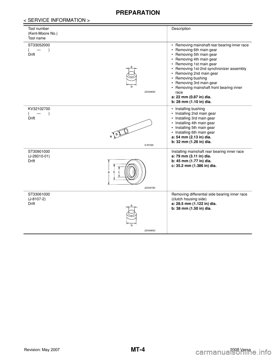
ST33052000
(—)
Drift• Removing mainshaft rear bearing inner race
• Removing 6th main gear
• Removing 5th main gear
• Removing 4th main gear
• Removing 1st main gear
• Removing 1st-2nd synchronizer assembly
• Removing 2nd main gear
• Removing bushing
• Removing 3rd main gear
• Removing mainshaft front bearing inner
race
a: 22 mm (0.87 in) dia.
b: 28 mm (1.10 in) dia.
KV32102700
(—)
Drift• Installing bushing
• Installing 2nd main gear
• Installing 3rd main gear
• Installing 4th main gear
• Installing 5th main gear
• Installing 6th main gear
a: 54 mm (2.13 in) dia.
b: 32 mm (1.26 in) dia.
ST30901000
(J-26010-01)
DriftInstalling mainshaft rear bearing inner race
a: 79 mm (3.11 in) dia.
b: 45 mm (1.77 in) dia.
c: 35.2 mm (1.386 in) dia.
ST33061000
(J-8107-2)
DriftRemoving differential side bearing inner race
(clutch housing side)
a: 28.5 mm (1.122 in) dia.
b: 38 mm (1.50 in) dia. Tool number
(Kent-Moore No.)
Tool nameDescription
ZZA0969D
S-NT065
ZZA0978D
ZZA0969D
Page 2293 of 2771
PREPARATION
MT-5
< SERVICE INFORMATION >
D
E
F
G
H
I
J
K
L
MA
B
MT
N
O
P
Commercial Service ToolINFOID:0000000001703131
Tool nameDescription
SocketRemoving and installing drain plug
a: 8 mm (0.31 in)
b: 5 mm (0.20 in)
SpacerRemoving mainshaft front bearing outer race
a: 25 mm (0.98 in) dia.
b: 25 mm (0.98 in)
Drift• Installing bushing
• Installing shift lever oil seal
• Installing control lever oil seal
a: 17 mm (0.67 in) dia.
DriftInstalling input shaft front bearing
a: 35 mm (1.38 in) dia.
b: 25 mm (0.98 in) dia.
DriftRemoving input shaft rear bearing
a: 24 mm (0.94 in) dia.
Drift• Removing differential side bearing inner
race (transaxle case side)
• Installing input shaft rear bearing
a: 43 mm (1.69 in) dia.
PCIB1776E
PCIB1780E
S-NT063
S-NT065
PCIB1779E
NT109
Page 2294 of 2771
MT-6
< SERVICE INFORMATION >
PREPARATION
DriftInstalling differential side bearing inner race
(clutch housing side)
a: 45 mm (1.77 in) dia.
b: 39 mm (1.54 in) dia.
DriftInstalling differential side bearing inner race
(transaxle case side)
a: 52 mm (2.05 in) dia.
b: 45 mm (1.77 in) dia.
Power tool• Loosening bolts and nuts Tool nameDescription
S-NT474
S-NT474
PBIC0190E