Page 2189 of 2771
LT-52
< SERVICE INFORMATION >
TURN SIGNAL AND HAZARD WARNING LAMPS
Wiring Diagram - TURN -
INFOID:0000000001704416
LKWA0329E
Page 2190 of 2771
TURN SIGNAL AND HAZARD WARNING LAMPS
LT-53
< SERVICE INFORMATION >
C
D
E
F
G
H
I
J
L
MA
B
LT
N
O
P
LKWA0330E
Page 2191 of 2771
LT-54
< SERVICE INFORMATION >
TURN SIGNAL AND HAZARD WARNING LAMPS
WKWA5808E
Page 2192 of 2771
TURN SIGNAL AND HAZARD WARNING LAMPS
LT-55
< SERVICE INFORMATION >
C
D
E
F
G
H
I
J
L
MA
B
LT
N
O
P
Terminal and Reference Value for BCMINFOID:0000000001704417
Refer to BCS-11, "Terminal and Reference Value for BCM" .
How to Proceed with Trouble DiagnosisINFOID:0000000001704418
1. Confirm the symptom or customer complaint.
2. Understand operation description and function description. Refer to LT-48, "
System Description" .
LKWA0332E
Page 2193 of 2771

LT-56
< SERVICE INFORMATION >
TURN SIGNAL AND HAZARD WARNING LAMPS
3. Perform the preliminary check. Refer to LT-56, "Preliminary Check" .
4. Check symptom and repair or replace the cause of the malfunction.
5. Do turn signal and hazard warning lamps operate normally? If YES, GO TO 6. If NO, GO TO 4.
6. INSPECTION END
Preliminary CheckINFOID:0000000001704419
CHECK POWER SUPPLY AND GROUND CIRCUIT FOR BCM
Refer to BCS-15, "BCM Power Supply and Ground Circuit Inspection" .
CONSULT-III Function (BCM)INFOID:0000000001704420
Refer to LT- 11 , "CONSULT-III Function (BCM)" .
Turn Signals Do Not OperateINFOID:0000000001704421
1.CHECK COMBINATION SWITCH INPUT SIGNAL
With CONSULT-III
1. Select “BCM” on CONSULT-III. Select “FLASHER” on “SELECT TEST ITEM” screen.
2. Select “DATA MONITOR” on “SELECT DIAG MODE” screen. Make sure that “TURN SIGNAL R” and
“TURN SIGNAL L” turns ON-OFF linked with operation of lighting switch.
Without CONSULT-III
Refer to LT-63, "
Combination Switch Inspection" .
OK or NG
OK >> Replace the BCM. BCS-18, "Removal and Installation of BCM"
NG >> Check combination switch (lighting switch). Refer to LT-63, "Combination Switch Inspection" .
Front Turn Signal Lamp Does Not OperateINFOID:0000000001704422
1.CHECK BULB
Verify the bulb standard of each turn signal lamp is correct. Refer to LT-113, "
Exterior Lamp" .
OK or NG
OK >> GO TO 2.
NG >> Replace turn signal lamp bulb. Refer to LT-59, "
Bulb Replacement for Front Turn Signal Lamp" .
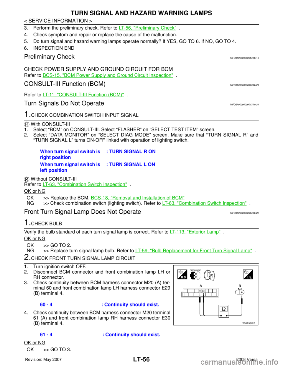
2.CHECK FRONT TURN SIGNAL LAMP CIRCUIT
1. Turn ignition switch OFF.
2. Disconnect BCM connector and front combination lamp LH or
RH connector.
3. Check continuity between BCM harness connector M20 (A) ter-
minal 60 and front combination lamp LH harness connector E29
(B) terminal 4.
4. Check continuity between BCM harness connector M20 terminal
61 (A) and front combination lamp RH harness connector E30
(B) terminal 4.
OK or NG
OK >> GO TO 3.When turn signal switch is
right position: TURN SIGNAL R ON
When turn signal switch is
left position: TURN SIGNAL L ON
60 - 4 : Continuity should exist.
61 - 4 : Continuity should exist.
WKIA5612E
Page 2194 of 2771

TURN SIGNAL AND HAZARD WARNING LAMPS
LT-57
< SERVICE INFORMATION >
C
D
E
F
G
H
I
J
L
MA
B
LT
N
O
P
NG >> Repair harness or connector.
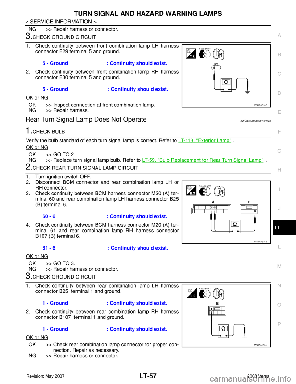
3.CHECK GROUND CIRCUIT
1. Check continuity between front combination lamp LH harness
connector E29 terminal 5 and ground.
2. Check continuity between front combination lamp RH harness
connector E30 terminal 5 and ground.
OK or NG
OK >> Inspect connection at front combination lamp.
NG >> Repair harness.
Rear Turn Signal Lamp Does Not OperateINFOID:0000000001704423
1.CHECK BULB
Verify the bulb standard of each turn signal lamp is correct. Refer to LT-113, "
Exterior Lamp" .
OK or NG
OK >> GO TO 2.
NG >> Replace turn signal lamp bulb. Refer to LT-59, "
Bulb Replacement for Rear Turn Signal Lamp" .
2.CHECK REAR TURN SIGNAL LAMP CIRCUIT
1. Turn ignition switch OFF.
2. Disconnect BCM connector and rear combination lamp LH or
RH connector.
3. Check continuity between BCM harness connector M20 (A) ter-
minal 60 and rear combination lamp LH harness connector B25
(B) terminal 6.
4. Check continuity between BCM harness connector M20 (A) ter-
minal 61 and rear combination lamp RH harness connector
B107 (B) terminal 6.
OK or NG
OK >> GO TO 3.
NG >> Repair harness or connector.
3.CHECK GROUND CIRCUIT
1. Check continuity between rear combination lamp LH harness
connector B25 terminal 1 and ground.
2. Check continuity between rear combination lamp RH harness
connector B107 terminal 1 and ground.
OK or NG
OK >> Check rear combination lamp connector for proper con-
nection. Repair as necessary.
NG >> Repair harness or connector.5 - Ground : Continuity should exist.
5 - Ground : Continuity should exist.
WKIA5613E
60 - 6 : Continuity should exist.
61 - 6 : Continuity should exist.
WKIA5614E
1 - Ground : Continuity should exist.
1 - Ground : Continuity should exist.
WKIA5615E
Page 2195 of 2771

LT-58
< SERVICE INFORMATION >
TURN SIGNAL AND HAZARD WARNING LAMPS
Hazard Warning Lamp Does Not Operate But Turn Signal Lamp Operates
INFOID:0000000001704424
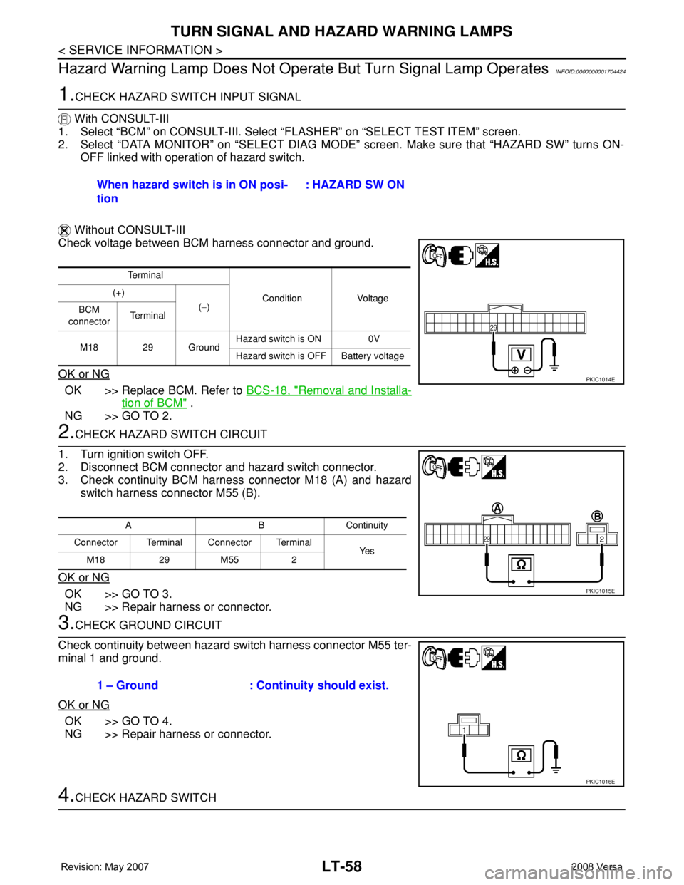
1.CHECK HAZARD SWITCH INPUT SIGNAL
With CONSULT-III
1. Select “BCM” on CONSULT-III. Select “FLASHER” on “SELECT TEST ITEM” screen.
2. Select “DATA MONITOR” on “SELECT DIAG MODE” screen. Make sure that “HAZARD SW” turns ON-
OFF linked with operation of hazard switch.
Without CONSULT-III
Check voltage between BCM harness connector and ground.
OK or NG
OK >> Replace BCM. Refer to BCS-18, "Removal and Installa-
tion of BCM" .
NG >> GO TO 2.
2.CHECK HAZARD SWITCH CIRCUIT
1. Turn ignition switch OFF.
2. Disconnect BCM connector and hazard switch connector.
3. Check continuity BCM harness connector M18 (A) and hazard
switch harness connector M55 (B).
OK or NG
OK >> GO TO 3.
NG >> Repair harness or connector.
3.CHECK GROUND CIRCUIT
Check continuity between hazard switch harness connector M55 ter-
minal 1 and ground.
OK or NG
OK >> GO TO 4.
NG >> Repair harness or connector.
4.CHECK HAZARD SWITCHWhen hazard switch is in ON posi-
tion : HAZARD SW ON
Te r m i n a l
Condition Voltage (+)
(−)
BCM
connectorTe r m i n a l
M18 29 GroundHazard switch is ON 0V
Hazard switch is OFF Battery voltage
PKIC1014E
ABContinuity
Connector Terminal Connector Terminal
Ye s
M18 29 M55 2
PKIC1015E
1 – Ground : Continuity should exist.
PKIC1016E
Page 2196 of 2771

TURN SIGNAL AND HAZARD WARNING LAMPS
LT-59
< SERVICE INFORMATION >
C
D
E
F
G
H
I
J
L
MA
B
LT
N
O
P
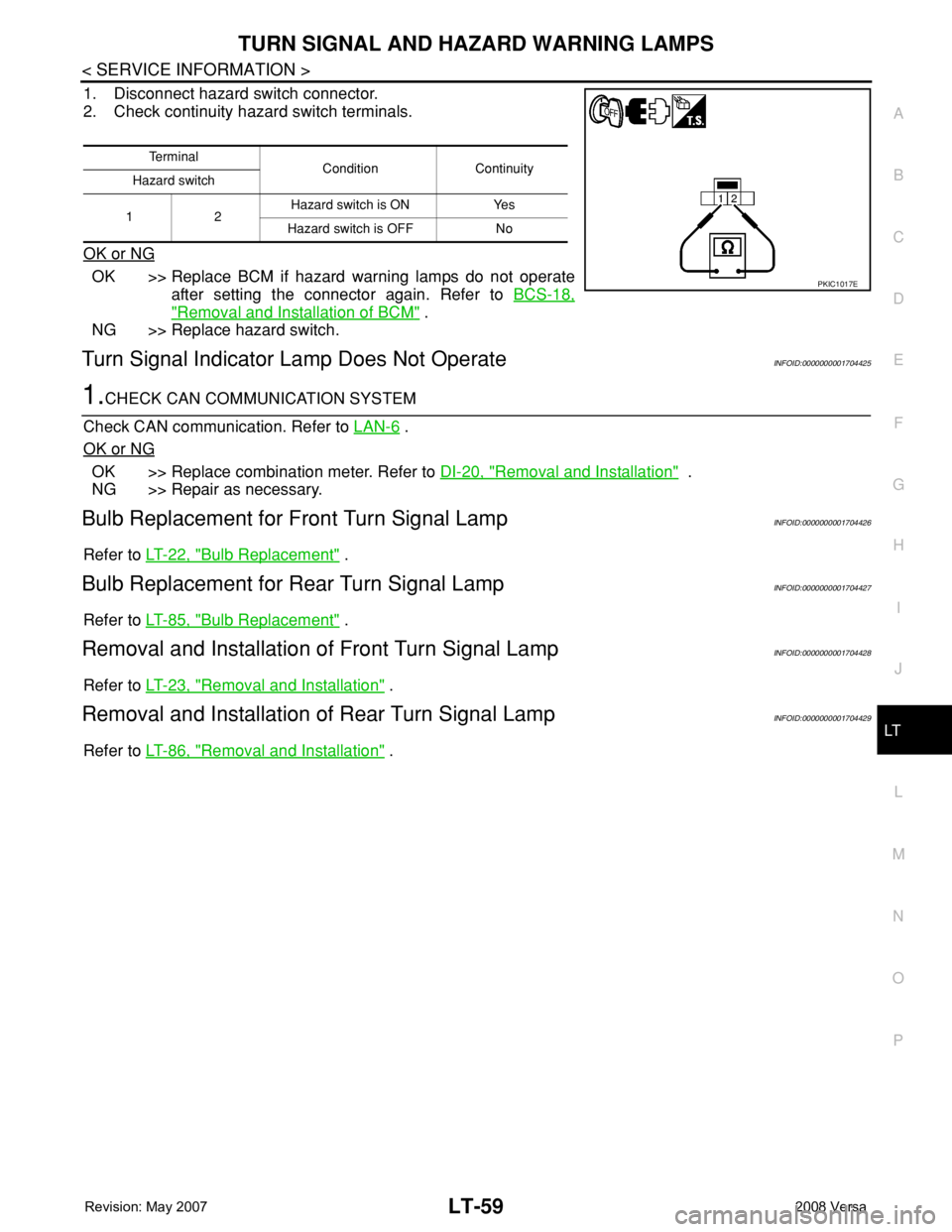
1. Disconnect hazard switch connector.
2. Check continuity hazard switch terminals.
OK or NG
OK >> Replace BCM if hazard warning lamps do not operate
after setting the connector again. Refer to BCS-18,
"Removal and Installation of BCM" .
NG >> Replace hazard switch.
Turn Signal Indicator Lamp Does Not OperateINFOID:0000000001704425
1.CHECK CAN COMMUNICATION SYSTEM
Check CAN communication. Refer to LAN-6
.
OK or NG
OK >> Replace combination meter. Refer to DI-20, "Removal and Installation" .
NG >> Repair as necessary.
Bulb Replacement for Front Turn Signal LampINFOID:0000000001704426
Refer to LT-22, "Bulb Replacement" .
Bulb Replacement for Rear Turn Signal LampINFOID:0000000001704427
Refer to LT-85, "Bulb Replacement" .
Removal and Installation of Front Turn Signal LampINFOID:0000000001704428
Refer to LT-23, "Removal and Installation" .
Removal and Installation of Rear Turn Signal LampINFOID:0000000001704429
Refer to LT-86, "Removal and Installation" .
Te r m i n a l
Condition Continuity
Hazard switch
12Hazard switch is ON Yes
Hazard switch is OFF No
PKIC1017E