Page 2282 of 2771

MA-22
< SERVICE INFORMATION >
CHASSIS AND BODY MAINTENANCE
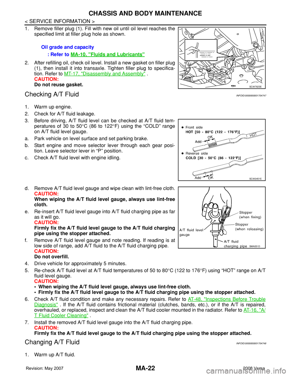
1. Remove filler plug (1). Fill with new oil until oil level reaches the
specified limit at filler plug hole as shown.
2. After refilling oil, check oil level. Install a new gasket on filler plug
(1), then install it into transaxle. Tighten filler plug to specifica-
tion. Refer to MT-17, "
Disassembly and Assembly" .
CAUTION:
Do not reuse gasket.
Checking A/T FluidINFOID:0000000001704747
1. Warm up engine.
2. Check for A/T fluid leakage.
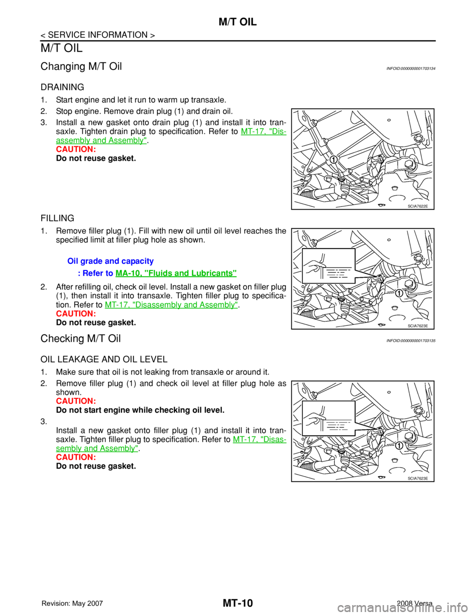
3. Before driving, A/T fluid level can be checked at A/T fluid tem-
peratures of 30 to 50°C (86 to 122°F) using the “COLD” range
on A/T fluid level gauge.
a. Park vehicle on level surface and set parking brake.
b. Start engine and move selector lever through each gear posi-
tion. Leave selector lever in “P” position.
c. Check A/T fluid level with engine idling.
d. Remove A/T fluid level gauge and wipe clean with lint-free cloth.
CAUTION:
When wiping the A/T fluid level gauge, always use lint-free
cloth.
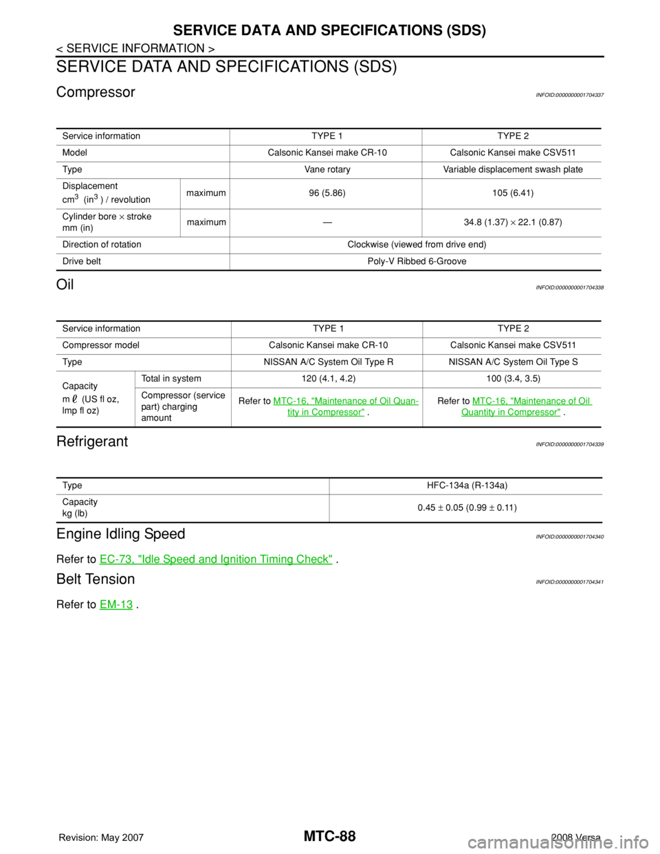
e. Re-insert A/T fluid level gauge into A/T fluid charging pipe as far
as it will go.
CAUTION:
Firmly fix the A/T fluid level gauge to the A/T fluid charging
pipe using the stopper attached.
f. Remove A/T fluid level gauge and note reading. If reading is at
low side of range, add A/T fluid to the A/T fluid charging pipe.
CAUTION:
Do not overfill.
4. Drive vehicle for approximately 5 minutes.
5. Re-check A/T fluid level at A/T fluid temperatures of 50 to 80°C (122 to 176°F) using “HOT” range on A/T
fluid level gauge.
CAUTION:
• When wiping the A/T fluid level gauge, always use lint-free cloth.
• Firmly fix the A/T fluid level gauge to the A/T fluid charging pipe using the stopper attached.
6. Check A/T fluid condition and make any necessary repairs. Refer to AT-48, "
Inspections Before Trouble
Diagnosis" . If the A/T fluid contains frictional material (clutches, bands, etc.), or if the A/T is repaired,
overhauled, or replaced, inspect and clean the A/T fluid cooler mounted in the radiator. Refer to AT-16, "
A/
T Fluid Cooler Cleaning" .
7. Install the removed A/T fluid level gauge into the A/T fluid charging pipe.
CAUTION:
Firmly fix the A/T fluid level gauge to the A/T fluid charging pipe using the stopper attached.
Changing A/T FluidINFOID:0000000001704748
1. Warm up A/T fluid.Oil grade and capacity
: Refer to MA-10, "
Fluids and Lubricants"
SCIA7623E
SCIA3451E
SMA051D
Page 2298 of 2771

MT-10
< SERVICE INFORMATION >
M/T OIL
M/T OIL
Changing M/T OilINFOID:0000000001703134
DRAINING
1. Start engine and let it run to warm up transaxle.
2. Stop engine. Remove drain plug (1) and drain oil.
3. Install a new gasket onto drain plug (1) and install it into tran-
saxle. Tighten drain plug to specification. Refer to MT-17, "
Dis-
assembly and Assembly".
CAUTION:
Do not reuse gasket.
FILLING
1. Remove filler plug (1). Fill with new oil until oil level reaches the
specified limit at filler plug hole as shown.
2. After refilling oil, check oil level. Install a new gasket on filler plug
(1), then install it into transaxle. Tighten filler plug to specifica-
tion. Refer to MT-17, "
Disassembly and Assembly".
CAUTION:
Do not reuse gasket.
Checking M/T OilINFOID:0000000001703135
OIL LEAKAGE AND OIL LEVEL
1. Make sure that oil is not leaking from transaxle or around it.
2. Remove filler plug (1) and check oil level at filler plug hole as
shown.
CAUTION:
Do not start engine while checking oil level.
3.
Install a new gasket onto filler plug (1) and install it into tran-
saxle. Tighten filler plug to specification. Refer to MT-17, "
Disas-
sembly and Assembly".
CAUTION:
Do not reuse gasket.
SCIA7622E
Oil grade and capacity
: Refer to MA-10, "
Fluids and Lubricants"
SCIA7623E
SCIA7623E
Page 2338 of 2771
MT-50
< SERVICE INFORMATION >
SERVICE DATA AND SPECIFICATIONS (SDS)
SERVICE DATA AND SPECIFICATIONS (SDS)
General SpecificationINFOID:0000000001703148
Engine typeMR18DE
Transaxle modelRS6F94R
Number of speeds6
Synchromesh typeWarner
Shift pattern
Gear ratio 1st3.727
2nd2.105
3rd1.452
4th1.171
5th0.971
6th0.811
Reverse 3.687
Final gear 3.933
Number of teeth Input gear 1st 11
2nd 19
3rd 31
4th 35
5th 35
6th 37
Reverse 11
Main gear 1st 41
2nd 40
3rd 45
4th 41
5th 34
6th 30
Reverse 42
Reverse idler gear Input/Output 28/29
Final gear Final gear/Pinion 59/15
Side gear/Pinion
mate gear21/18
Oil capacity
(US pt, Imp pt)Approx. 2.0 (4-1/4, 3-1/2)
Remarks Reverse synchronizer Installed
Triple-cone synchronizer 1st and 2nd
PCIB1769E
Page 2426 of 2771

MTC-88
< SERVICE INFORMATION >
SERVICE DATA AND SPECIFICATIONS (SDS)
SERVICE DATA AND SPECIFICATIONS (SDS)
CompressorINFOID:0000000001704337
OilINFOID:0000000001704338
RefrigerantINFOID:0000000001704339
Engine Idling SpeedINFOID:0000000001704340
Refer to EC-73, "Idle Speed and Ignition Timing Check" .
Belt TensionINFOID:0000000001704341
Refer to EM-13 .
Service information TYPE 1 TYPE 2
Model Calsonic Kansei make CR-10 Calsonic Kansei make CSV511
Type Vane rotary Variable displacement swash plate
Displacement
cm
3 (in3 ) / revolutionmaximum 96 (5.86) 105 (6.41)
Cylinder bore × stroke
mm (in)maximum — 34.8 (1.37) × 22.1 (0.87)
Direction of rotation Clockwise (viewed from drive end)
Drive belt Poly-V Ribbed 6-Groove
Service information TYPE 1 TYPE 2
Compressor model Calsonic Kansei make CR-10 Calsonic Kansei make CSV511
Type NISSAN A/C System Oil Type R NISSAN A/C System Oil Type S
Capacity
m (US fl oz,
lmp fl oz)Total in system 120 (4.1, 4.2) 100 (3.4, 3.5)
Compressor (service
part) charging
amountRefer to MTC-16, "
Maintenance of Oil Quan-
tity in Compressor" .Refer to MTC-16, "
Maintenance of Oil
Quantity in Compressor" .
Ty p eHFC-134a (R-134a)
Capacity
kg (lb)0.45 ± 0.05 (0.99 ± 0.11)