2008 NISSAN LATIO ignition
[x] Cancel search: ignitionPage 515 of 2771
INTELLIGENT KEY SYSTEM
BL-81
< SERVICE INFORMATION >
C
D
E
F
G
H
J
K
L
MA
B
BL
N
O
P
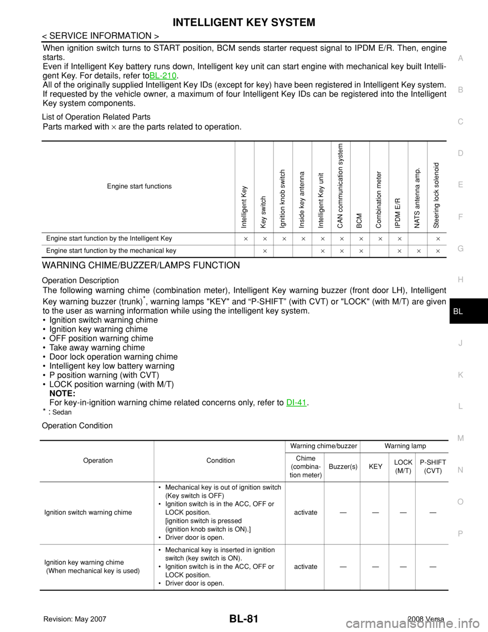
When ignition switch turns to START position, BCM sends starter request signal to IPDM E/R. Then, engine
starts.
Even if Intelligent Key battery runs down, Intelligent key unit can start engine with mechanical key built Intelli-
gent Key. For details, refer toBL-210
.
All of the originally supplied Intelligent Key IDs (except for key) have been registered in Intelligent Key system.
If requested by the vehicle owner, a maximum of four Intelligent Key IDs can be registered into the Intelligent
Key system components.
List of Operation Related Parts
Parts marked with × are the parts related to operation.
WARNING CHIME/BUZZER/LAMPS FUNCTION
Operation Description
The following warning chime (combination meter), Intelligent Key warning buzzer (front door LH), Intelligent
Key warning buzzer (trunk)
*, warning lamps "KEY" and “P-SHIFT” (with CVT) or "LOCK" (with M/T) are given
to the user as warning information while using the intelligent key system.
• Ignition switch warning chime
• Ignition key warning chime
• OFF position warning chime
• Take away warning chime
• Door lock operation warning chime
• Intelligent key low battery warning
• P position warning (with CVT)
• LOCK position warning (with M/T)
NOTE:
For key-in-ignition warning chime related concerns only, refer to DI-41
.
* :
Sedan
Operation Condition
Engine start functions
Intelligent Key
Key switch
Ignition knob switch
Inside key antenna
Intelligent Key unit
CAN communication system
BCM
Combination meter
IPDM E/R
NATS antenna amp.
Steering lock solenoid
Engine start function by the Intelligent Key××××××××× ×
Engine start function by the mechanical key× ××× ×××
Operation ConditionWarning chime/buzzer Warning lamp
Chime
(combina-
tion meter)Buzzer(s) KEYLOCK
(M/T)P-SHIFT
(CVT)
Ignition switch warning chime• Mechanical key is out of ignition switch
(Key switch is OFF)
• Ignition switch is in the ACC, OFF or
LOCK position.
[ignition switch is pressed
(ignition knob switch is ON).]
• Driver door is open.activate — — — —
Ignition key warning chime
(When mechanical key is used)• Mechanical key is inserted in ignition
switch (key switch is ON).
• Ignition switch is in the ACC, OFF or
LOCK position.
• Driver door is open.activate — — — —
Page 516 of 2771

BL-82
< SERVICE INFORMATION >
INTELLIGENT KEY SYSTEM
List of Operation Related Parts
Parts marked with × are the parts related to operation.
P position warning (CVT)When selector lever is in other than P po-
sition, ignition switch is turned from ON to
OFF.activate — — — Flash
OFF position warn-
ing chimeFor internal• Ignition switch is turned from ACC to
OFF.
[ignition switch is pressed (ignition knob
switch is ON).]
• Ignition switch is in the LOCK position
and pressed for 1 second.activate — — Flash —
For externalWhen driver door is opened and then
closed while the OFF position warning
chime above is operating—activate—— —
Ta k e a w a y w a r n i n gRight after
door is closedRight after door is closed and the following
conditions are met.
• Ignition knob is pressed and in rotatable
or rotated state
• Intelligent Key can not be detected in-
side the vehicle—activateFlash
(red)——
Any door is
openedAny door is opened and the following con-
ditions are met.
• Ignition knob is pressed and in rotatable
or rotated state
• Intelligent Key unit will perform key ID
verification with Intelligent Key through
inside key antenna every 5 second, if
the key ID verification is NG.——Flash
(red)——
Ta k e a w a y
from the win-
dowTake away from the window and the fol-
lowing conditions are met.
• Ignition knob is pressed and in rotatable
or rotated state
• Vehicle speed below 5 km/h (3 m.p.h.)
• Intelligent Key unit will perform key ID
verification with Intelligent Key through
inside key antenna every 30 second, if
the key ID verification is NG.
(This warning function will be disabled if
mechanical key is inserted into the key
cylinder.)
NOTE:
Default setting of this function is OFF.activate —Flash
(red)——
Door lock opera-
tion warningLock opera-
tion with re-
quest switchLock operation with request switch and
the following condition is met.
• Intelligent Key is inside the vehicle—activate—— —
Intelligent Key low battery warningWhen Intelligent Key is low battery, Intelli-
gent Key unit is detected after ignition
switch is turned ON.——Flash
(green)—— Operation ConditionWarning chime/buzzer Warning lamp
Chime
(combina-
tion meter)Buzzer(s) KEYLOCK
(M/T)P-SHIFT
(CVT)
Page 517 of 2771
INTELLIGENT KEY SYSTEM
BL-83
< SERVICE INFORMATION >
C
D
E
F
G
H
J
K
L
MA
B
BL
N
O
P
CHANGE SETTINGS FUNCTION
The settings for each function can be changed with the CONSULT-III.
Changing Settings Using CONSULT-III
The settings for the Intelligent Key system functions can be changed using CONSULT-III (WORK SUPPORT).
Refer to BL-101, "
CONSULT-III Application Item".
NOTE:
Once a function setting is changed, it will remain effective even if the battery is disconnected.
INTELLIGENT KEY REGISTRATION
Intelligent Key-ID registration is performed using the CONSULT-III.
CAUTION:
• After a new Intelligent Key-ID is registered, be sure to check the function.
• When registering an additional Intelligent Key-ID, take any Intelligent Keys already registered and
Intelligent Keys for any other vehicles out of the vehicle before starting.
CONSULT-III can be used to check and delete Intelligent Key-IDs.
For further information, see the CONSULT-III Operation Manual NATS.
STEERING LOCK SOLENOID REGISTRATION
Steering Lock Solenoid ID Registration
CAUTION:
• The method for registering a steering lock solenoid ID depends on the status of the steering lock
solenoid and Intelligent Key unit (new or old unit).
• After registration is completed, press ignition switch with an Intelligent Key in the vehicle so that it
can be turned, and confirm that it cannot be turned even when ignition switch is pressed without an
Intelligent Key in the vehicle.
For further information, see the CONSULT-III Operation Manual NATS-IVIS/NVIS.
CAN Communication System DescriptionINFOID:0000000001704000
Refer to LAN-6.
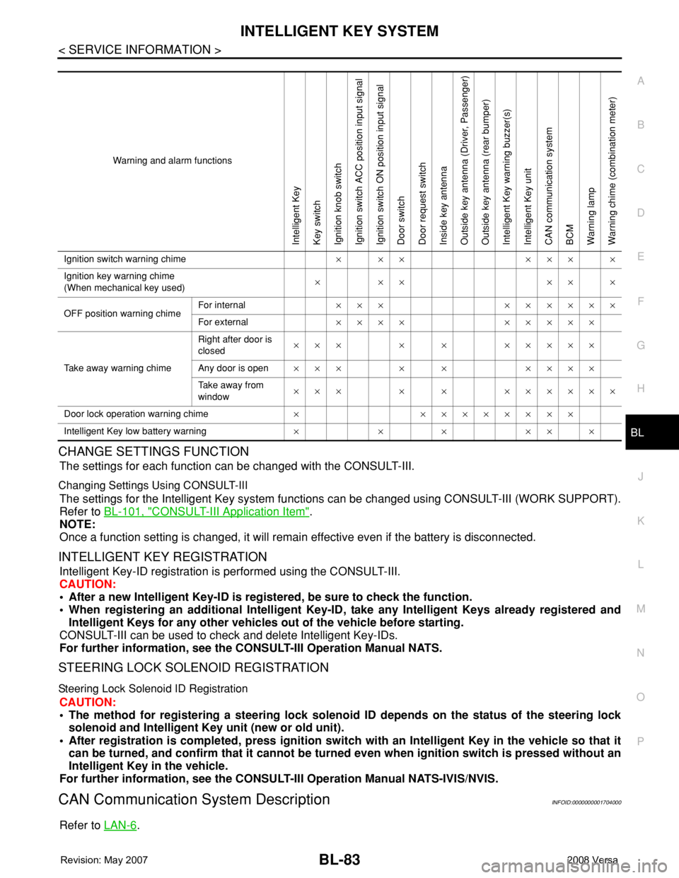
Warning and alarm functions
Intelligent Key
Key switch
Ignition knob switch
Ignition switch ACC position input signal
Ignition switch ON position input signal
Door switch
Door request switch
Inside key antenna
Outside key antenna (Driver, Passenger)
Outside key antenna (rear bumper)
Intelligent Key warning buzzer(s)
Intelligent Key unit
CAN communication system
BCM
Warning lamp
Warning chime (combination meter)
Ignition switch warning chime× ×× ××× ×
Ignition key warning chime
(When mechanical key used)××× ×××
OFF position warning chimeFor internal××× ××××××
For external×××× ×××××
Take away warning chimeRight after door is
closed××× × × ×××××
Any door is open××× × × ××××
Take away from
window××× × × ××××××
Door lock operation warning chime× ××××××××
Intelligent Key low battery warning××××××
Page 530 of 2771
BL-96
< SERVICE INFORMATION >
INTELLIGENT KEY SYSTEM
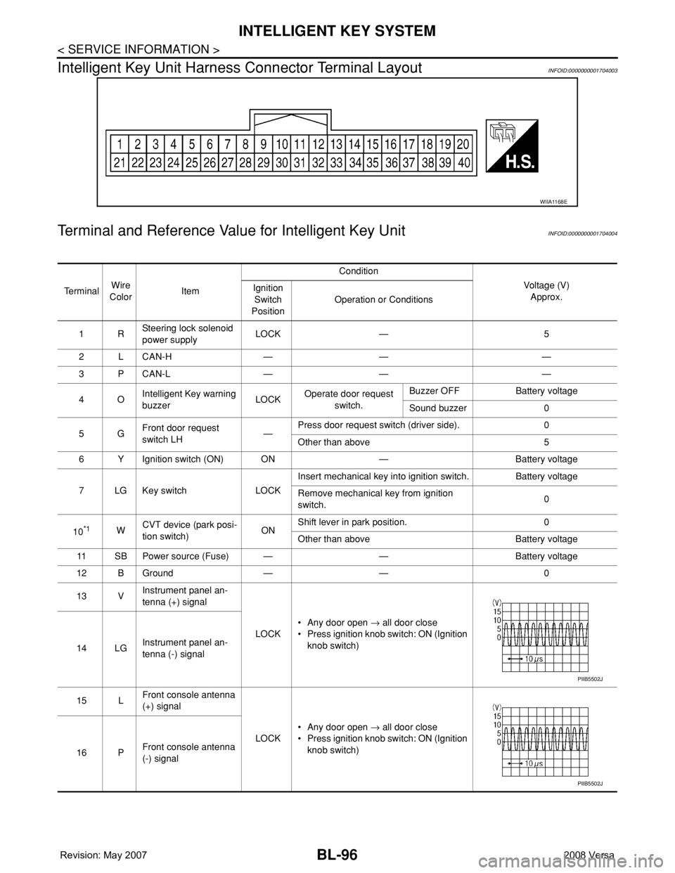
Intelligent Key Unit Harness Connector Terminal Layout
INFOID:0000000001704003
Terminal and Reference Value for Intelligent Key UnitINFOID:0000000001704004
WIIA1168E
Te r m i n a lWire
ColorItemCondition
Voltage (V)
Approx. Ignition
Switch
PositionOperation or Conditions
1RSteering lock solenoid
power supplyLOCK — 5
2 L CAN-H — — —
3 P CAN-L — — —
4OIntelligent Key warning
buzzerLOCKOperate door request
switch.Buzzer OFF Battery voltage
Sound buzzer 0
5GFront door request
switch LH—Press door request switch (driver side). 0
Other than above 5
6 Y Ignition switch (ON) ON — Battery voltage
7 LG Key switch LOCKInsert mechanical key into ignition switch. Battery voltage
Remove mechanical key from ignition
switch.0
10
*1WCVT device (park posi-
tion switch)ONShift lever in park position. 0
Other than above Battery voltage
11 SB Power source (Fuse) — — Battery voltage
12 B Ground — — 0
13 VInstrument panel an-
tenna (+) signal
LOCK• Any door open → all door close
• Press ignition knob switch: ON (Ignition
knob switch)
14 LGInstrument panel an-
tenna (-) signal
15 LFront console antenna
(+) signal
LOCK• Any door open → all door close
• Press ignition knob switch: ON (Ignition
knob switch)
16 PFront console antenna
(-) signal
PIIB5502J
PIIB5502J
Page 531 of 2771
INTELLIGENT KEY SYSTEM
BL-97
< SERVICE INFORMATION >
C
D
E
F
G
H
J
K
L
MA
B
BL
N
O
P
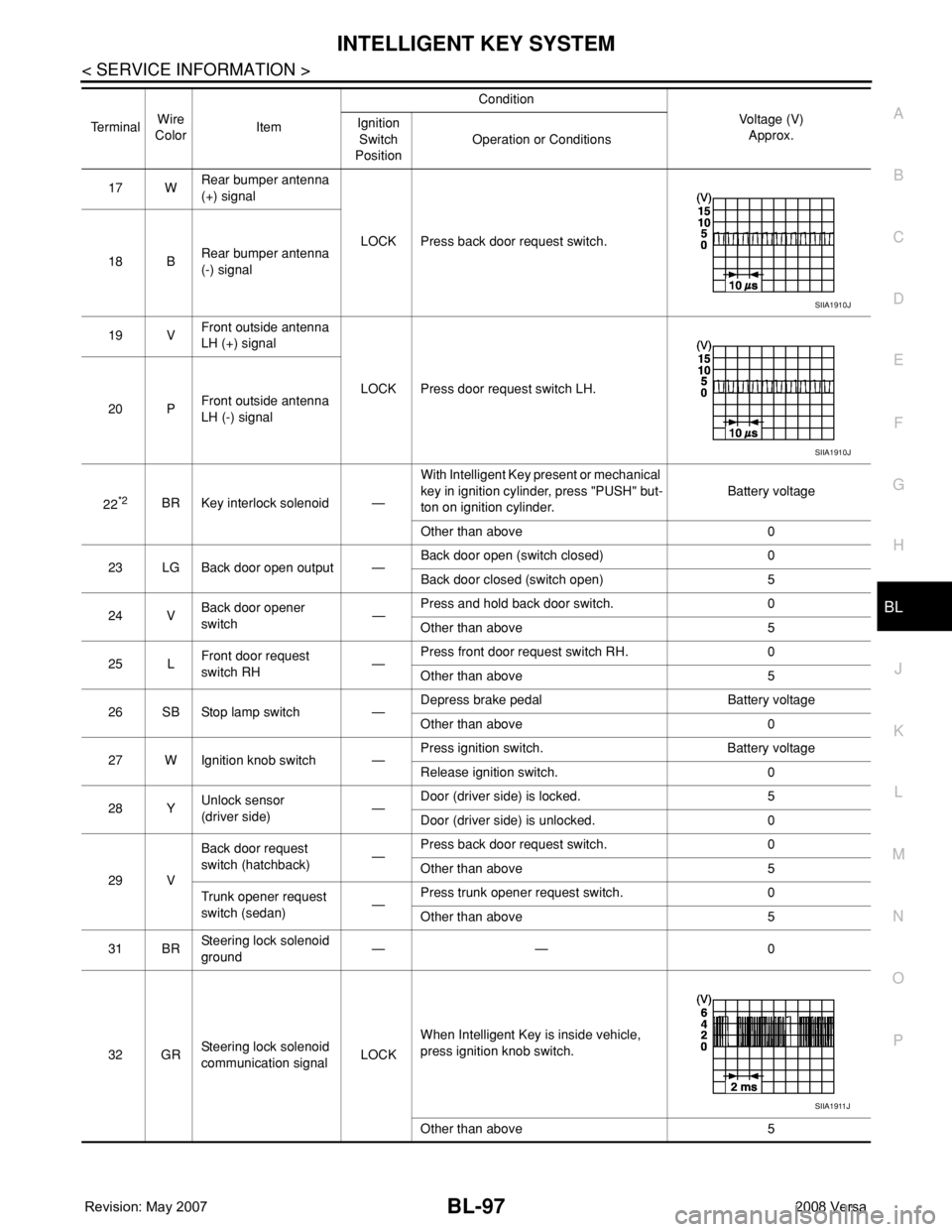
17 WRear bumper antenna
(+) signal
LOCK Press back door request switch.
18 BRear bumper antenna
(-) signal
19 VFront outside antenna
LH (+) signal
LOCK Press door request switch LH.
20 PFront outside antenna
LH (-) signal
22
*2BR Key interlock solenoid —With Intelligent Key present or mechanical
key in ignition cylinder, press "PUSH" but-
ton on ignition cylinder.Battery voltage
Other than above 0
23 LG Back door open output —Back door open (switch closed) 0
Back door closed (switch open) 5
24 VBack door opener
switch—Press and hold back door switch. 0
Other than above 5
25 LFront door request
switch RH—Press front door request switch RH. 0
Other than above 5
26 SB Stop lamp switch —Depress brake pedal Battery voltage
Other than above 0
27 W Ignition knob switch —Press ignition switch. Battery voltage
Release ignition switch. 0
28 YUnlock sensor
(driver side)—Door (driver side) is locked. 5
Door (driver side) is unlocked. 0
29 VBack door request
switch (hatchback)—Press back door request switch. 0
Other than above 5
Trunk opener request
switch (sedan)—Press trunk opener request switch. 0
Other than above 5
31 BRSteering lock solenoid
ground—— 0
32 GRSteering lock solenoid
communication signalLOCKWhen Intelligent Key is inside vehicle,
press ignition knob switch.
Other than above 5 TerminalWire
ColorItemCondition
Voltage (V)
Approx. Ignition
Switch
PositionOperation or Conditions
SIIA1910J
SIIA1910J
SIIA1911J
Page 532 of 2771
BL-98
< SERVICE INFORMATION >
INTELLIGENT KEY SYSTEM
*1: With continuously variable transmission (CVT).
*2: With manual transmission (M/T).
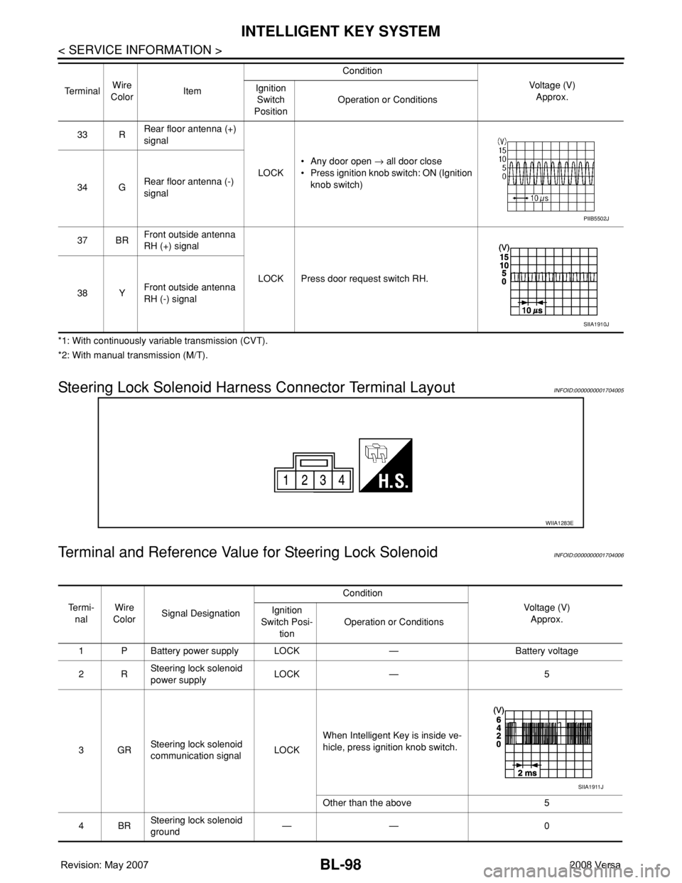
Steering Lock Solenoid Harness Connector Terminal LayoutINFOID:0000000001704005
Terminal and Reference Value for Steering Lock SolenoidINFOID:0000000001704006
33 RRear floor antenna (+)
signal
LOCK• Any door open → all door close
• Press ignition knob switch: ON (Ignition
knob switch)
34 GRear floor antenna (-)
signal
37 BRFront outside antenna
RH (+) signal
LOCK Press door request switch RH.
38 YFront outside antenna
RH (-) signal Te r m i n a lWire
ColorItemCondition
Voltage (V)
Approx. Ignition
Switch
PositionOperation or Conditions
PIIB5502J
SIIA1910J
WIIA1283E
Te r m i -
nalWire
ColorSignal DesignationCondition
Voltage (V)
Approx. Ignition
Switch Posi-
tionOperation or Conditions
1 P Battery power supply LOCK — Battery voltage
2RSteering lock solenoid
power supplyLOCK — 5
3GRSteering lock solenoid
communication signalLOCKWhen Intelligent Key is inside ve-
hicle, press ignition knob switch.
Other than the above 5
4BRSteering lock solenoid
ground—— 0
SIIA1911J
Page 533 of 2771
INTELLIGENT KEY SYSTEM
BL-99
< SERVICE INFORMATION >
C
D
E
F
G
H
J
K
L
MA
B
BL
N
O
P
Terminal and Reference Value for BCMINFOID:0000000001704007
Refer to BCS-11, "Terminal and Reference Value for BCM".
Trouble Diagnosis ProcedureINFOID:0000000001704008
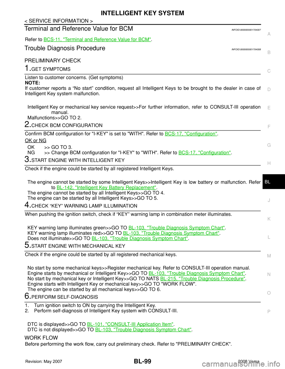
PRELIMINARY CHECK
1.GET SYMPTOMS
Listen to customer concerns. (Get symptoms)
NOTE:
If customer reports a “No start” condition, request all Intelligent Keys to be brought to the dealer in case of
Intelligent Key system malfunction.
Intelligent Key or mechanical key service request>>For further information, refer to CONSULT-III operation
manual.
Malfunctions>>GO TO 2.
2.CHECK BCM CONFIGURATION
Confirm BCM configuration for "I-KEY" is set to "WITH". Refer to BCS-17, "
Configuration".
OK or NG
OK >> GO TO 3.
NG >> Change BCM configuration for "I-KEY" to "WITH". Refer to BCS-17, "
Configuration".
3.START ENGINE WITH INTELLIGENT KEY
Check if the engine could be started by all registered Intelligent Keys.
The engine cannot be started by some Intelligent Keys>>Intelligent Key is low battery or malfunction. Refer
to BL-142, "
Intelligent Key Battery Replacement".
The engine cannot be started by all Intelligent Keys>>GO TO 4.
The engine can be started by all Intelligent Keys>>GO TO 5.
4.CHECK “KEY” WARNING LAMP ILLUMINATION
When pushing the ignition switch, check if “KEY” warning lamp in combination meter illuminates.
KEY warning lamp illuminates green>>GO TO BL-103, "
Trouble Diagnosis Symptom Chart".
KEY warning lamp illuminates red>>GO TO BL-103, "
Trouble Diagnosis Symptom Chart".
Does not illuminate>>GO TO BL-103, "
Trouble Diagnosis Symptom Chart".
5.START ENGINE WITH MECHANICAL KEY
Check if the engine could be started by all registered mechanical keys.
No start by some mechanical keys>>Register mechanical key. Refer to CONSULT-III operation manual.
Engine starts by mechanical or Intelligent Key>>GO TO BL-103, "
Trouble Diagnosis Symptom Chart".
No start by mechanical key or Intelligent Key>>GO TO NATS BL-215, "
Trouble Diagnosis Procedure".
Engine starts with Intelligent Key or mechanical key>>GO TO "WORK FLOW".
The engine can be started by all mechanical keys>>GO TO 6.
6.PERFORM SELF-DIAGNOSIS
1. Turn ignition switch to ON by carrying the Intelligent Key.
2. Perform self-diagnosis of Intelligent Key system with CONSULT-III.
DTC is displayed>>GO TO BL-101, "
CONSULT-III Application Item".
DTC is not displayed>>GO TO BL-103, "
Trouble Diagnosis Symptom Chart".
WORK FLOW
Before performing the work flow, carry out preliminary check. Refer to "PRELIMINARY CHECK".
Page 535 of 2771

INTELLIGENT KEY SYSTEM
BL-101
< SERVICE INFORMATION >
C
D
E
F
G
H
J
K
L
MA
B
BL
N
O
P
CONSULT-III Application ItemINFOID:0000000001704011
SELF-DIAGNOSTIC RESULTS
DATA MONITOR
*: Select “SELECTION FROM MENU”.
ACTIVE TEST
Part to be diagnosed Test item, Diagnosis mode Description
Intelligent KeyWORK SUPPORT Changes settings for each function.
SELF-DIAG RESULTS Intelligent Key unit performs CAN communication diagnosis.
DATA MONITOR Displays Intelligent Key unit input data in real time.
CAN DIAGNOSTIC SUPPORT
MONITORThe results of transmit/receive diagnosis of CAN Communication can
be read.
ACTIVE TESTOperation of electrical loads can be checked by sending driving signal
to them.
ECU PART NUMBER Displays Intelligent Key unit part No.
Self-diag results Description Diagnosis procedure Reference page
CAN COMM Malfunction is detected in CAN communication. Check CAN communication system.BL-109
CAN COMM2 Intelligent Key unit internal malfunction Check CAN communication system.BL-109
STRG COMMMalfunction is detected in communication of Intelli-
gent Key unit and steering lock solenoid.Check steering lock solenoid.BL-131
I-KEY C/U Intelligent Key unit internal malfunction Replace Intelligent Key unit.BL-142
IMMU NATS malfunction Check NATS.BL-210
Monitor item Content
PUSH SW Indicates [ON/OFF] condition of ignition knob switch.
KEY SW Indicates [ON/OFF] condition of key switch.
DR REQ SW Indicates [ON/OFF] condition of door request switch (driver side).
AS REQ SW Indicates [ON/OFF] condition of door request switch (passenger side).
BD/TR REQ SW Indicates [ON/OFF] condition of back door request switch.
IGN SW Indicates [ON/OFF] condition of ignition switch in ON position.
ACC SW Indicates [ON/OFF] condition of ignition switch in ACC position.
STOP LAMP SW Indicates [ON/OFF] condition of stop lamp switch.
P RANGE SW Indicates [ON/OFF] condition of shift lever park position.
BD OPEN SW Indicates [ON/OFF] condition of back door open switch.
DOOR LOCK SIG* Indicates [ON/OFF] condition of door lock signal from Intelligent Key button.
DOOR UNLOCK SIG* Indicates [ON/OFF] condition of door unlock signal from Intelligent Key button
DOOR SW DR*Indicates [OPEN/CLOSE] condition of front door switch driver side from BCM via CAN communica-
tion line.
DOOR SW AS*Indicates [OPEN/CLOSE] condition of front door switch passenger side from BCM via CAN commu-
nication line.
DOOR SW RR* Indicates [OPEN/CLOSE] condition of rear door switch RH from BCM via CAN communication line.
DOOR SW RL* Indicates [OPEN/CLOSE] condition of rear door switch LH from BCM via CAN communication line.
TRUNK SW* This is displayed even when it is not equipped.
VEHICLE SPEED* Indicates [km/h] condition of vehicle speed.