2008 NISSAN LATIO ignition
[x] Cancel search: ignitionPage 470 of 2771

BL-36
< SERVICE INFORMATION >
POWER DOOR LOCK SYSTEM
3. According to the trouble diagnosis chart, repair or replace the cause of the malfunction. Refer to BL-103,
"Trouble Diagnosis Symptom Chart" .
4. Does power door lock system operate normally? OK: GO TO 5, NG: GO TO 3.
5. Inspection End.
CONSULT-III Function (BCM)INFOID:0000000001703962
CONSULT-III can display each diagnostic item using the diagnostic test modes shown following.
WORK SUPPORT
DATA MONITOR
*: With Remote Keyless Entry system
**: With Intelligent Key system
ACTIVE TEST
BCM
diagnostic test itemDiagnostic mode Description
Inspection by partWORK SUPPORTSupports inspections and adjustments. Commands are transmitted to the
BCM for setting the status suitable for required operation, input/output sig-
nals are received from the BCM and received date is displayed.
DATA MONITOR Displays BCM input/output data in real time.
ACTIVE TESTOperation of electrical loads can be checked by sending drive signal to
them.
SELF-DIAG RESULTS Displays BCM self-diagnosis results.
CAN DIAG SUPPORT MNTRThe result of transmit/receive diagnosis of CAN communication can be
read.
ECU PART NUMBER BCM part number can be read.
CONFIGURATION Performs BCM configuration read/write functions.
Work item Description
DOOR LOCK-UNLOCK SET Select unlock mode can be changed in this mode. Selects ON-OFF of select unlock mode.
ANTI-LOCK OUT SET Key reminder door mode can be changed in this mode. Selects ON-OFF of key reminder door mode.
Monitor item Content
IGN ON SW Indicates [ON/OFF] condition of ignition switch in ON position.
KEY ON SW Indicates [ON/OFF] condition of key switch.
CDL LOCK SW Indicates [ON/OFF] condition of lock signal from door lock and unlock switch.
CDL UNLOCK SW Indicates [ON/OFF] condition of unlock signal from door lock and unlock switch.
DOOR SW-DR Indicates [ON/OFF] condition of front door switch LH.
DOOR SW-AS Indicates [ON/OFF] condition of front door switch RH.
DOOR SW-RR Indicates [ON/OFF] condition of rear door switch RH.
DOOR SW-RL Indicates [ON/OFF] condition of rear door switch LH.
BACK DOOR SW Indicates [ON/OFF] condition of back door switch.
KEY CYL LK-SW Indicates [ON/OFF] condition of lock signal from key cylinder.
KEY CYL UN-SW Indicates [ON/OFF] condition of unlock signal from key cylinder.
KEYLESS LOCK* Indicates [ON/OFF] condition of lock signal from keyfob.
KEYLESS UNLOCK* Indicates [ON/OFF] condition of unlock signal from keyfob.
I-KEY LOCK** Indicates [ON/OFF] condition of lock signal from door request switch.
I-KEY UNLOCK** Indicates [ON/OFF] condition of unlock signal from door request switch.
Page 472 of 2771
BL-38
< SERVICE INFORMATION >
POWER DOOR LOCK SYSTEM
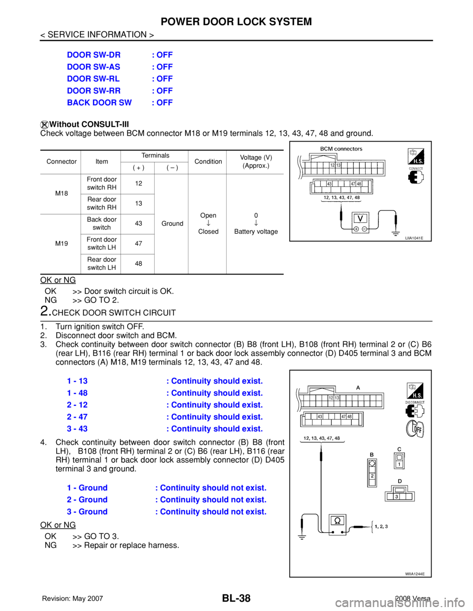
Without CONSULT-III
Check voltage between BCM connector M18 or M19 terminals 12, 13, 43, 47, 48 and ground.
OK or NG
OK >> Door switch circuit is OK.
NG >> GO TO 2.
2.CHECK DOOR SWITCH CIRCUIT
1. Turn ignition switch OFF.
2. Disconnect door switch and BCM.
3. Check continuity between door switch connector (B) B8 (front LH), B108 (front RH) terminal 2 or (C) B6
(rear LH), B116 (rear RH) terminal 1 or back door lock assembly connector (D) D405 terminal 3 and BCM
connectors (A) M18, M19 terminals 12, 13, 43, 47 and 48.
4. Check continuity between door switch connector (B) B8 (front
LH), B108 (front RH) terminal 2 or (C) B6 (rear LH), B116 (rear
RH) terminal 1 or back door lock assembly connector (D) D405
terminal 3 and ground.
OK or NG
OK >> GO TO 3.
NG >> Repair or replace harness.DOOR SW-DR : OFF
DOOR SW-AS : OFF
DOOR SW-RL : OFF
DOOR SW-RR : OFF
BACK DOOR SW : OFF
Connector ItemTe r m i n a l s
ConditionVoltage (V)
(Approx.)
( + ) ( – )
M18Front door
switch RH12
GroundOpen
↓
Closed0
↓
Battery voltage Rear door
switch RH13
M19Back door
switch43
Front door
switch LH47
Rear door
switch LH48
LIIA1041E
1 - 13 : Continuity should exist.
1 - 48 : Continuity should exist.
2 - 12 : Continuity should exist.
2 - 47 : Continuity should exist.
3 - 43 : Continuity should exist.
1 - Ground : Continuity should not exist.
2 - Ground : Continuity should not exist.
3 - Ground : Continuity should not exist.
WIIA1244E
Page 474 of 2771
BL-40
< SERVICE INFORMATION >
POWER DOOR LOCK SYSTEM
NG >> Repair or replace harness.
Door Switch Check (Sedan)INFOID:0000000001703966
1.CHECK DOOR SWITCHES INPUT SIGNAL
With CONSULT-III
Check door switches ("DOOR SW-DR", "DOOR SW-AS", "DOOR SW-RL", "DOOR SW-RR") in DATA MONI-
TOR mode with CONSULT–III. Refer to BL-36, "
CONSULT-III Function (BCM)" .
• When doors are open:
• When doors are closed:
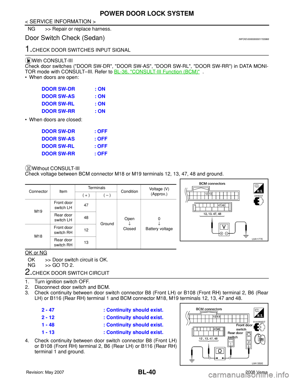
Without CONSULT-III
Check voltage between BCM connector M18 or M19 terminals 12, 13, 47, 48 and ground.
OK or NG
OK >> Door switch circuit is OK.
NG >> GO TO 2.
2.CHECK DOOR SWITCH CIRCUIT
1. Turn ignition switch OFF.
2. Disconnect door switch and BCM.
3. Check continuity between door switch connector B8 (Front LH) or B108 (Front RH) terminal 2, B6 (Rear
LH) or B116 (Rear RH) terminal 1 and BCM connector M18, M19 terminals 12, 13, 47 and 48.
4. Check continuity between door switch connector B8 (Front LH)
or B108 (Front RH) terminal 2, B6 (Rear LH) or B116 (Rear RH)
terminal 1 and ground.DOOR SW-DR : ON
DOOR SW-AS : ON
DOOR SW-RL : ON
DOOR SW-RR : ON
DOOR SW-DR : OFF
DOOR SW-AS : OFF
DOOR SW-RL : OFF
DOOR SW-RR : OFF
Connector ItemTe r m i n a l s
ConditionVoltage (V)
(Approx.)
( + ) ( – )
M19Front door
switch LH47
GroundOpen
↓
Closed0
↓
Battery voltage Rear door
switch LH48
M18Front door
switch RH12
Rear door
switch RH13
LIIA1177E
2 - 47 : Continuity should exist.
2 - 12 : Continuity should exist.
1 - 48 : Continuity should exist.
1 - 13 : Continuity should exist.
LIIA1350E
Page 475 of 2771
POWER DOOR LOCK SYSTEM
BL-41
< SERVICE INFORMATION >
C
D
E
F
G
H
J
K
L
MA
B
BL
N
O
P
OK or NG
OK >> GO TO 3.
NG >> Repair or replace harness.
3.CHECK DOOR SWITCHES
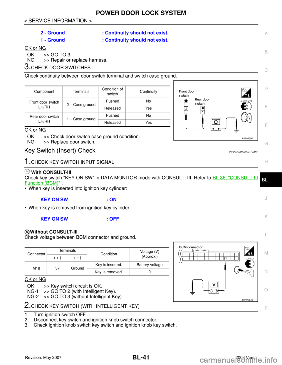
Check continuity between door switch terminal and switch case ground.
OK or NG
OK >> Check door switch case ground condition.
NG >> Replace door switch.
Key Switch (Insert) CheckINFOID:0000000001703967
1.CHECK KEY SWITCH INPUT SIGNAL
With CONSULT-III
Check key switch "KEY ON SW" in DATA MONITOR mode with CONSULT–III. Refer to BL-36, "
CONSULT-III
Function (BCM)" .
• When key is inserted into ignition key cylinder:
• When key is removed from ignition key cylinder:
Without CONSULT-III
Check voltage between BCM connector and ground.
OK or NG
OK >> Key switch circuit is OK.
NG-1 >> GO TO 2 (with Intelligent Key).
NG-2 >> GO TO 3 (without Intelligent Key).
2.CHECK KEY SWITCH (WITH INTELLIGENT KEY)
1. Turn ignition switch OFF.
2. Disconnect key switch and ignition knob switch connector.
3. Check ignition knob switch key switch and ignition knob key switch.2 - Ground : Continuity should not exist.
1 - Ground : Continuity should not exist.
Component TerminalsCondition of
switchContinuity
Front door switch
LH/RH2 – Case groundPushed No
Released Yes
Rear door switch
LH/RH1 – Case groundPushed No
Released Yes
LIIA0550E
KEY ON SW : ON
KEY ON SW : OFF
ConnectorTe r m i n a l s
ConditionVoltage (V)
(Approx.)
( + ) ( – )
M18 37 GroundKey is inserted. Battery voltage
Key is removed. 0
LIIA0567E
Page 476 of 2771
BL-42
< SERVICE INFORMATION >
POWER DOOR LOCK SYSTEM
OK or NG
OK >> Check the following.
• 10A fuse (No. 31, located in fuse and fusible link
block)
• Harness for open or short between key switch and ignition knob switch and fuse
• Harness for open or short between BCM and key switch and ignition knob switch
NG >> Replace key switch and ignition knob switch.
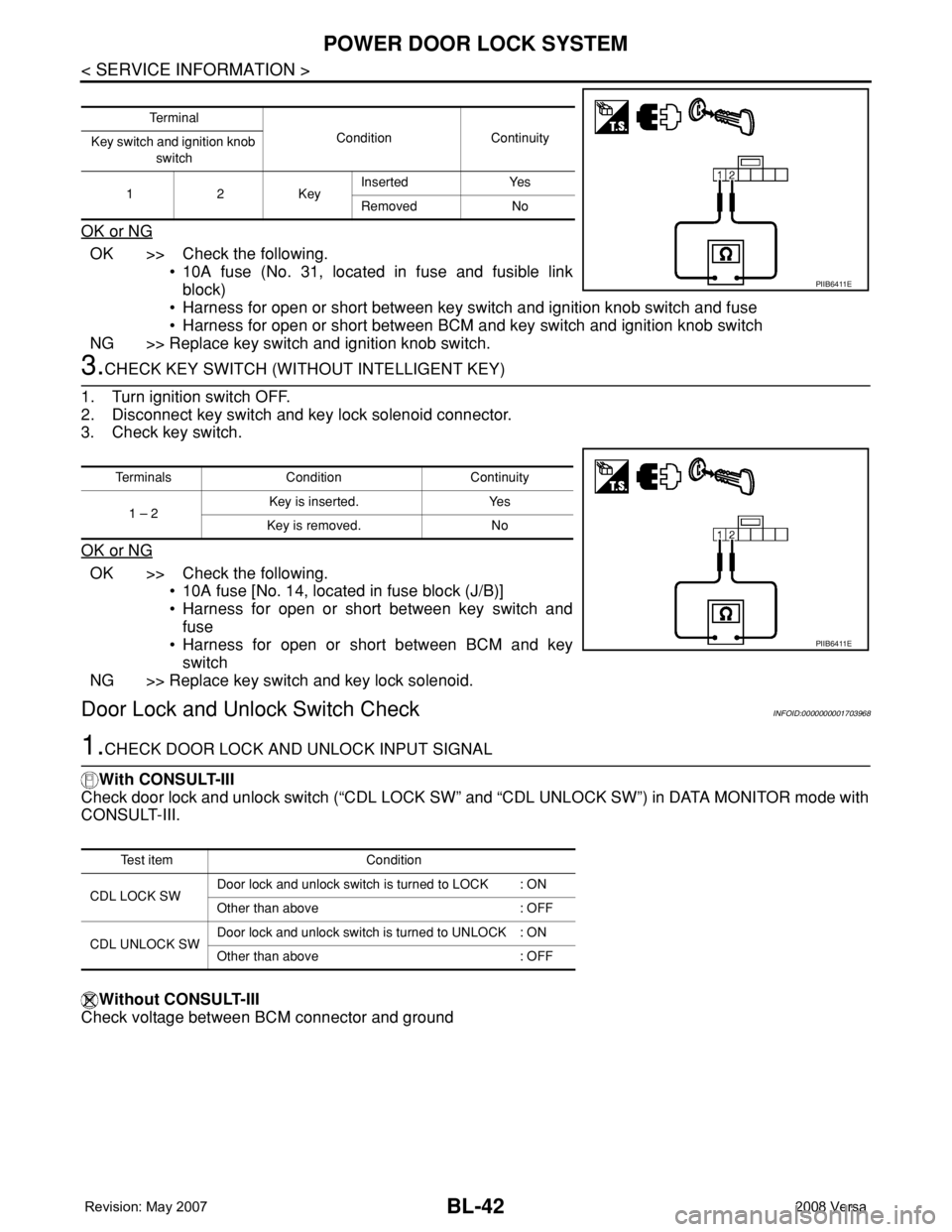
3.CHECK KEY SWITCH (WITHOUT INTELLIGENT KEY)
1. Turn ignition switch OFF.
2. Disconnect key switch and key lock solenoid connector.
3. Check key switch.
OK or NG
OK >> Check the following.
• 10A fuse [No. 14, located in fuse block (J/B)]
• Harness for open or short between key switch and
fuse
• Harness for open or short between BCM and key
switch
NG >> Replace key switch and key lock solenoid.
Door Lock and Unlock Switch CheckINFOID:0000000001703968
1.CHECK DOOR LOCK AND UNLOCK INPUT SIGNAL
With CONSULT-III
Check door lock and unlock switch (“CDL LOCK SW” and “CDL UNLOCK SW”) in DATA MONITOR mode with
CONSULT-III.
Without CONSULT-III
Check voltage between BCM connector and ground
Te r m i n a l
Condition Continuity
Key switch and ignition knob
switch
12KeyInserted Yes
Removed No
PIIB6411E
Terminals Condition Continuity
1 – 2Key is inserted. Yes
Key is removed. No
PIIB6411E
Test item Condition
CDL LOCK SWDoor lock and unlock switch is turned to LOCK : ON
Other than above : OFF
CDL UNLOCK SWDoor lock and unlock switch is turned to UNLOCK : ON
Other than above : OFF
Page 477 of 2771
POWER DOOR LOCK SYSTEM
BL-43
< SERVICE INFORMATION >
C
D
E
F
G
H
J
K
L
MA
B
BL
N
O
P
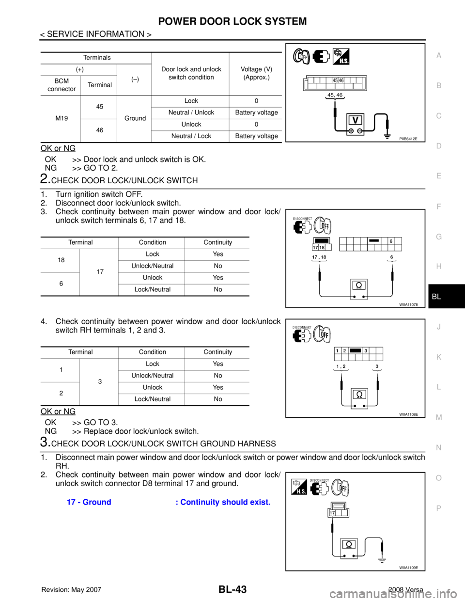
OK or NG
OK >> Door lock and unlock switch is OK.
NG >> GO TO 2.
2.CHECK DOOR LOCK/UNLOCK SWITCH
1. Turn ignition switch OFF.
2. Disconnect door lock/unlock switch.
3. Check continuity between main power window and door lock/
unlock switch terminals 6, 17 and 18.
4. Check continuity between power window and door lock/unlock
switch RH terminals 1, 2 and 3.
OK or NG
OK >> GO TO 3.
NG >> Replace door lock/unlock switch.
3.CHECK DOOR LOCK/UNLOCK SWITCH GROUND HARNESS
1. Disconnect main power window and door lock/unlock switch or power window and door lock/unlock switch
RH.
2. Check continuity between main power window and door lock/
unlock switch connector D8 terminal 17 and ground.
Te r m i n a l s
Door lock and unlock
switch conditionVoltage (V)
(Approx.) (+)
(–)
BCM
connectorTe r m i n a l
M1945
GroundLock 0
Neutral / Unlock Battery voltage
46Unlock 0
Neutral / Lock Battery voltage
PIIB6412E
Terminal Condition Continuity
18
17Lock Yes
Unlock/Neutral No
6Unlock Yes
Lock/Neutral No
WIIA1107E
Terminal Condition Continuity
1
3Lock Yes
Unlock/Neutral No
2Unlock Yes
Lock/Neutral No
WIIA1108E
17 - Ground : Continuity should exist.
WIIA1109E
Page 479 of 2771
POWER DOOR LOCK SYSTEM
BL-45
< SERVICE INFORMATION >
C
D
E
F
G
H
J
K
L
MA
B
BL
N
O
P
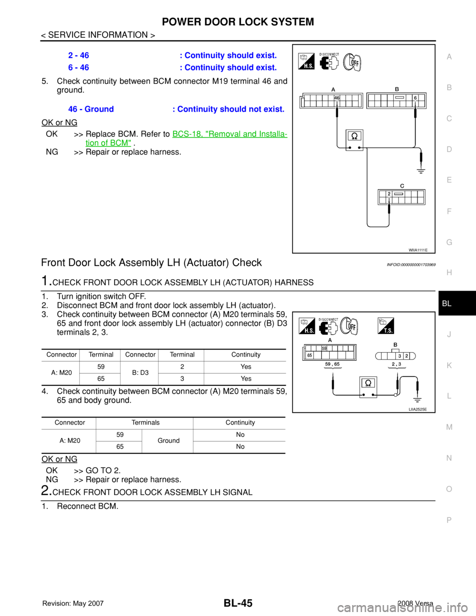
5. Check continuity between BCM connector M19 terminal 46 and
ground.
OK or NG
OK >> Replace BCM. Refer to BCS-18, "Removal and Installa-
tion of BCM" .
NG >> Repair or replace harness.
Front Door Lock Assembly LH (Actuator) CheckINFOID:0000000001703969
1.CHECK FRONT DOOR LOCK ASSEMBLY LH (ACTUATOR) HARNESS
1. Turn ignition switch OFF.
2. Disconnect BCM and front door lock assembly LH (actuator).
3. Check continuity between BCM connector (A) M20 terminals 59,
65 and front door lock assembly LH (actuator) connector (B) D3
terminals 2, 3.
4. Check continuity between BCM connector (A) M20 terminals 59,
65 and body ground.
OK or NG
OK >> GO TO 2.
NG >> Repair or replace harness.
2.CHECK FRONT DOOR LOCK ASSEMBLY LH SIGNAL
1. Reconnect BCM.2 - 46 : Continuity should exist.
6 - 46 : Continuity should exist.
46 - Ground : Continuity should not exist.
W I I A 1111 E
Connector Terminal Connector Terminal Continuity
A: M2059
B: D32Yes
65 3 Yes
Connector Terminals Continuity
A: M2059
GroundNo
65 No
LIIA2525E
Page 480 of 2771
BL-46
< SERVICE INFORMATION >
POWER DOOR LOCK SYSTEM
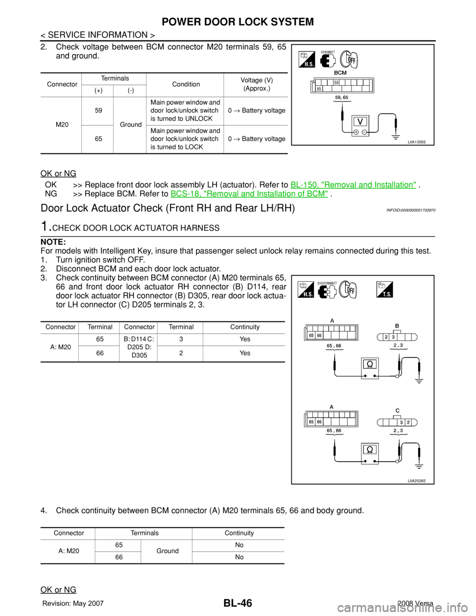
2. Check voltage between BCM connector M20 terminals 59, 65
and ground.
OK or NG
OK >> Replace front door lock assembly LH (actuator). Refer to BL-150, "Removal and Installation" .
NG >> Replace BCM. Refer to BCS-18, "
Removal and Installation of BCM" .
Door Lock Actuator Check (Front RH and Rear LH/RH)INFOID:0000000001703970
1.CHECK DOOR LOCK ACTUATOR HARNESS
NOTE:
For models with Intelligent Key, insure that passenger select unlock relay remains connected during this test.
1. Turn ignition switch OFF.
2. Disconnect BCM and each door lock actuator.
3. Check continuity between BCM connector (A) M20 terminals 65,
66 and front door lock actuator RH connector (B) D114, rear
door lock actuator RH connector (B) D305, rear door lock actua-
tor LH connector (C) D205 terminals 2, 3.
4. Check continuity between BCM connector (A) M20 terminals 65, 66 and body ground.
OK or NG
ConnectorTe r m i n a l s
ConditionVoltage (V)
(Approx.)
(+) (-)
M2059
GroundMain power window and
door lock/unlock switch
is turned to UNLOCK0 → Battery voltage
65Main power window and
door lock/unlock switch
is turned to LOCK0 → Battery voltage
LIIA1355E
Connector Terminal Connector Terminal Continuity
A: M2065 B: D114 C:
D205 D:
D3053Yes
66 2 Yes
LIIA2526E
Connector Terminals Continuity
A: M2065
GroundNo
66 No