Page 1149 of 2771
BASIC SERVICE PROCEDURE
EC-75
< SERVICE INFORMATION >
C
D
E
F
G
H
I
J
K
L
MA
EC
N
P O
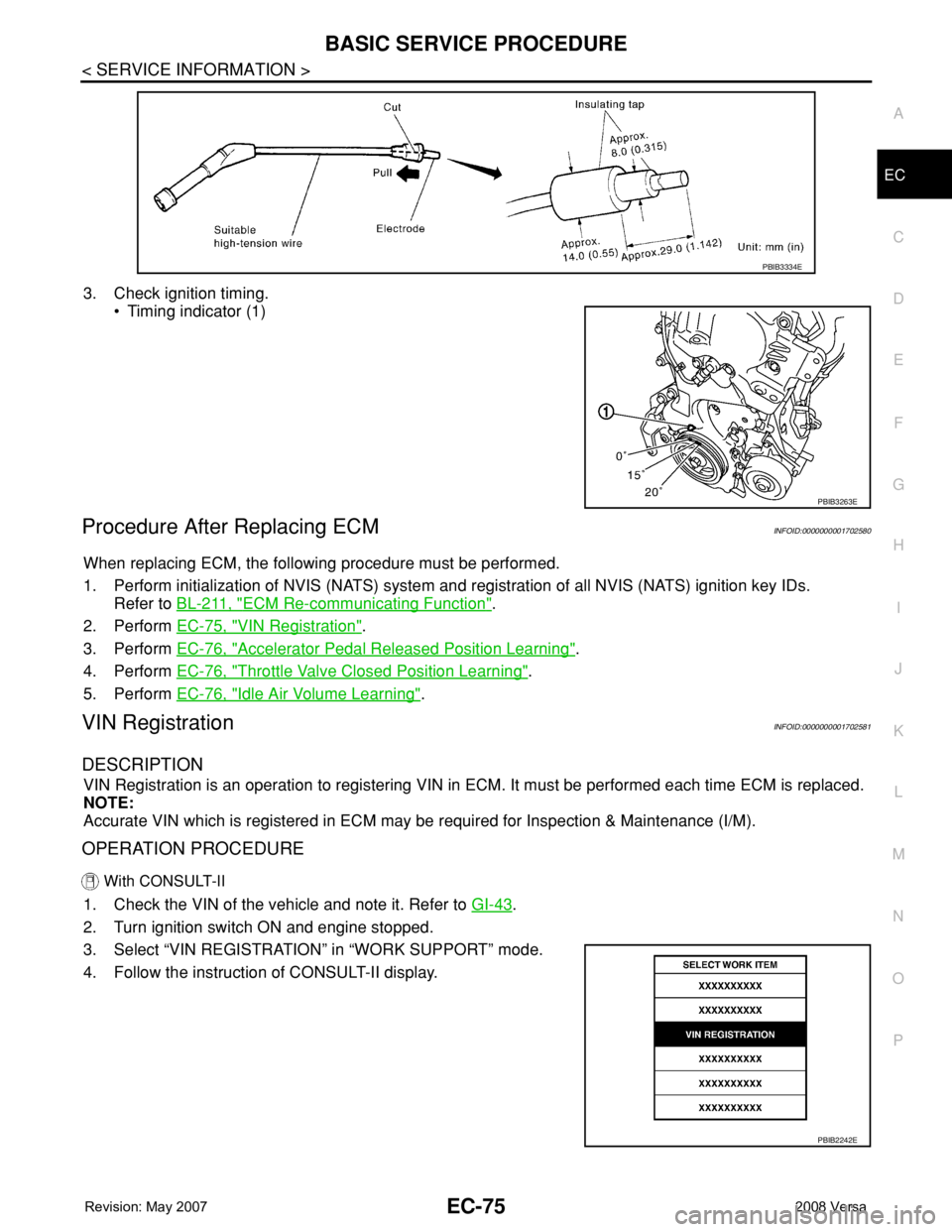
3. Check ignition timing.
• Timing indicator (1)
Procedure After Replacing ECMINFOID:0000000001702580
When replacing ECM, the following procedure must be performed.
1. Perform initialization of NVIS (NATS) system and registration of all NVIS (NATS) ignition key IDs.
Refer to BL-211, "
ECM Re-communicating Function".
2. Perform EC-75, "
VIN Registration".
3. Perform EC-76, "
Accelerator Pedal Released Position Learning".
4. Perform EC-76, "
Throttle Valve Closed Position Learning".
5. Perform EC-76, "
Idle Air Volume Learning".
VIN RegistrationINFOID:0000000001702581
DESCRIPTION
VIN Registration is an operation to registering VIN in ECM. It must be performed each time ECM is replaced.
NOTE:
Accurate VIN which is registered in ECM may be required for Inspection & Maintenance (I/M).
OPERATION PROCEDURE
With CONSULT-II
1. Check the VIN of the vehicle and note it. Refer to GI-43.
2. Turn ignition switch ON and engine stopped.
3. Select “VIN REGISTRATION” in “WORK SUPPORT” mode.
4. Follow the instruction of CONSULT-II display.
PBIB3334E
PBIB3263E
PBIB2242E
Page 1395 of 2771
DTC P0442 EVAP CONTROL SYSTEM
EC-321
< SERVICE INFORMATION >
C
D
E
F
G
H
I
J
K
L
MA
EC
N
P O
With CONSULT-II>>GO TO 6.
Without CONSULT-II>>GO TO 7.
6.CHECK FOR EVAP LEAK
With CONSULT-II
1. Turn ignition switch ON.
2. Select “EVAP SYSTEM CLOSE” of “WORK SUPPORT” mode
with CONSULT-II.
3. Touch “START” and apply pressure into the EVAP line until the
pressure indicator reaches the middle of the bar graph.
CAUTION:
• Never use compressed air or a high pressure pump.
• Do not exceed 4.12 kPa (0.042 kg/cm
2, 0.6 psi) of pressure
in the system.
4. Using EVAP leak detector, locate the EVAP leak. For the leak
detector, refer to the instruction manual for more details.
Refer to EC-31, "
Description".
OK or NG
OK >> GO TO 8.
NG >> Repair or replace.
7.CHECK FOR EVAP LEAK
Without CONSULT-II
1. Turn ignition switch OFF.
2. Apply 12 volts DC to EVAP canister vent control valve. The
valve will close. (Continue to apply 12 volts until the end of test.)
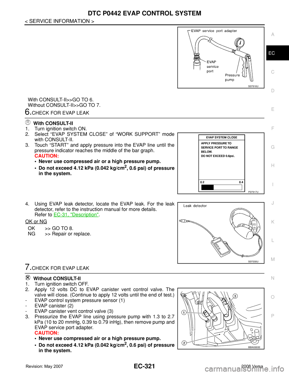
- EVAP control system pressure sensor (1)
- EVAP canister (2)
- EVAP canister vent control valve (3)
3. Pressurize the EVAP line using pressure pump with 1.3 to 2.7
kPa (10 to 20 mmHg, 0.39 to 0.79 inHg), then remove pump and
EVAP service port adapter.
CAUTION:
• Never use compressed air or a high pressure pump.
• Do not exceed 4.12 kPa (0.042 kg/cm
2, 0.6 psi) of pressure
in the system.
SEF916U
PEF917U
SEF200U
BBIA0693E
Page 1447 of 2771
DTC P0455 EVAP CONTROL SYSTEM
EC-373
< SERVICE INFORMATION >
C
D
E
F
G
H
I
J
K
L
MA
EC
N
P O
Refer to EC-343, "Component Inspection".
OK or NG
OK >> GO TO 8.
NG >> Repair or replace EVAP canister vent control valve and O-ring.
8.INSTALL THE PRESSURE PUMP
To locate the EVAP leak, install EVAP service port adapter and pressure pump to EVAP service port securely.
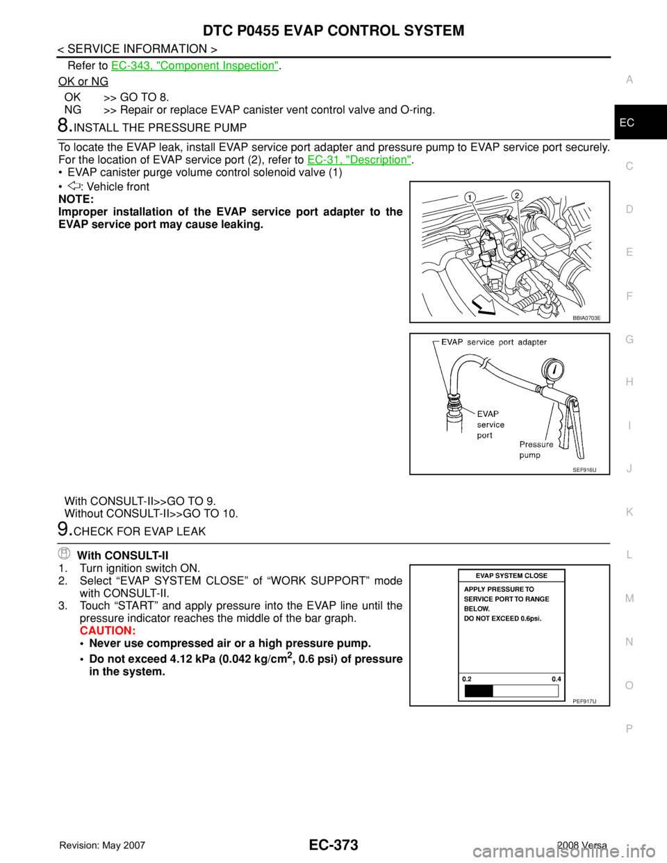
For the location of EVAP service port (2), refer to EC-31, "
Description".
• EVAP canister purge volume control solenoid valve (1)
• : Vehicle front
NOTE:
Improper installation of the EVAP service port adapter to the
EVAP service port may cause leaking.
With CONSULT-II>>GO TO 9.
Without CONSULT-II>>GO TO 10.
9.CHECK FOR EVAP LEAK
With CONSULT-II
1. Turn ignition switch ON.
2. Select “EVAP SYSTEM CLOSE” of “WORK SUPPORT” mode
with CONSULT-II.
3. Touch “START” and apply pressure into the EVAP line until the
pressure indicator reaches the middle of the bar graph.
CAUTION:
• Never use compressed air or a high pressure pump.
• Do not exceed 4.12 kPa (0.042 kg/cm
2, 0.6 psi) of pressure
in the system.
BBIA0703E
SEF916U
PEF917U
Page 1454 of 2771
EC-380
< SERVICE INFORMATION >
DTC P0456 EVAP CONTROL SYSTEM
3.CHECK FUEL FILLER CAP FUNCTION
Check for air releasing sound while opening the fuel filler cap.
OK or NG
OK >> GO TO 5.
NG >> GO TO 4.
4.CHECK FUEL TANK VACUUM RELIEF VALVE
Refer to EC-33, "
Component Inspection".
OK or NG
OK >> GO TO 5.
NG >> Replace fuel filler cap with a genuine one.
5.INSTALL THE PRESSURE PUMP
To locate the EVAP leak, install EVAP service port adapter and pres-
sure pump to EVAP service port securely. For the location of EVAP
service port (2), refer to EC-31, "
Description".
• EVAP canister purge volume control solenoid valve (1)
• : Vehicle front
NOTE:
Improper installation of the EVAP service port adapter to the
EVAP service port may cause leaking.
With CONSULT-II>>GO TO 6.
Without CONSULT-II>>GO TO 7.
6.CHECK FOR EVAP LEAK
With CONSULT-II
1. Turn ignition switch ON.
2. Select “EVAP SYSTEM CLOSE” of “WORK SUPPORT” mode with CONSULT-II.
3. Touch “START” and apply pressure into the EVAP line until the
pressure indicator reaches the middle of the bar graph.
CAUTION:
• Never use compressed air or a high pressure pump.
• Do not exceed 4.12 kPa (0.042 kg/cm
2, 0.6 psi) of pressure
in the system.
BBIA0703E
SEF916U
PEF917U
Page 1513 of 2771
DTC P1572 ASCD BRAKE SWITCH
EC-439
< SERVICE INFORMATION >
C
D
E
F
G
H
I
J
K
L
MA
EC
N
P O
DTC Confirmation ProcedureINFOID:0000000001702961
CAUTION:
Always drive vehicle at a safe speed.
NOTE:
• If DTC Confirmation Procedure has been previously conducted, always turn ignition switch OFF and wait at
least 10 seconds before conducting the next test.
• Procedure for malfunction B is not described here. It takes extremely long time to complete procedure for
malfunction B. By performing procedure for malfunction A, the incident that causes malfunction B can be
detected.
TESTING CONDITION:
Steps 4 and 5 may be conducted with the drive wheels lifted in the shop or by driving the vehicle. If a
road test is expected to be easier, it is unnecessary to lift the vehicle.
WITH CONSULT-II
1. Start engine.
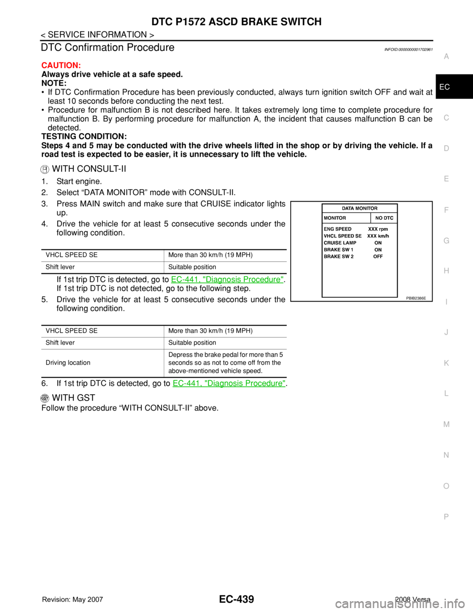
2. Select “DATA MONITOR” mode with CONSULT-II.
3. Press MAIN switch and make sure that CRUISE indicator lights
up.
4. Drive the vehicle for at least 5 consecutive seconds under the
following condition.
If 1st trip DTC is detected, go to EC-441, "
Diagnosis Procedure".
If 1st trip DTC is not detected, go to the following step.
5. Drive the vehicle for at least 5 consecutive seconds under the
following condition.
6. If 1st trip DTC is detected, go to EC-441, "
Diagnosis Procedure".
WITH GST
Follow the procedure “WITH CONSULT-II” above.
VHCL SPEED SE More than 30 km/h (19 MPH)
Shift lever Suitable position
VHCL SPEED SE More than 30 km/h (19 MPH)
Shift lever Suitable position
Driving locationDepress the brake pedal for more than 5
seconds so as not to come off from the
above-mentioned vehicle speed.
PBIB2386E
Page 1590 of 2771

EC-516
< SERVICE INFORMATION >
ASCD INDICATOR
ASCD INDICATOR
Component DescriptionINFOID:0000000001703053
ASCD indicator lamp illuminates to indicate ASCD operation status. Lamp has two indicators, CRUISE and
SET, and is integrated in combination meter.
CRUISE indicator illuminates when MAIN switch on ASCD steering switch is turned ON to indicate that ASCD
system is ready for operation.
SET indicator illuminates when following conditions are met.
• CRUISE indicator is illuminated.
• SET/COAST switch on ASCD steering switch is turned ON while vehicle speed is within the range of ASCD
setting.
SET indicator remains lit during ASCD control.
Refer to EC-28
for the ASCD function.
CONSULT-II Reference Value in Data Monitor ModeINFOID:0000000001703054
Specification data are reference value.
MONITOR ITEM CONDITION SPECIFICATION
CRUISE LAMP • Ignition switch: ONMAIN switch: Pressed at 1st time
→ 2ndON → OFF
SET LAMP• MAIN switch: ON
• Vehicle: Between 40 km/h (25
MPH) and 144 km/h (89 MPH)ASCD: Operating ON
ASCD: Not operating OFF
Page 1591 of 2771
ASCD INDICATOR
EC-517
< SERVICE INFORMATION >
C
D
E
F
G
H
I
J
K
L
MA
EC
N
P O
Wiring DiagramINFOID:0000000001703055
Diagnosis ProcedureINFOID:0000000001703056
1.CHECK OVERALL FUNCTION
Check ASCD indicator under the following conditions.
BBWA3005E
Page 1592 of 2771
EC-518
< SERVICE INFORMATION >
ASCD INDICATOR
OK or NG
OK >>INSPECTION END
NG >> GO TO 2.
2.CHECK DTC
Check that DTC U1000 or U1001 is not displayed.
Ye s o r N o
Yes >> Perform trouble diagnoses for DTC U1000, U1001, refer to EC-143.
No >> GO TO 3.
3.CHECK COMBINATION METER OPERATION
Does combination meter operate normally?
Ye s o r N o
Ye s > > G O T O 4 .
No >> Check combination meter circuit. Refer to DI-4
.
4.CHECK INTERMITTENT INCIDENT
Refer to EC-136
.
>>INSPECTION END
ASCD INDICATOR CONDITION SPECIFICATION
CRUISE LAMP • Ignition switch: ONMAIN switch: Pressed at 1st
time → 2ndON → OFF
SET LAMP•MAIN switch: ON
• Vehicle: Between 40 km/h (25
MPH) and 144 km/h (89
MPH)ASCD: Operating ON
ASCD: Not operating OFF