Page 1033 of 2771

DI-12
< SERVICE INFORMATION >
COMBINATION METERS
If the diagnosis function is activated with “trip A” displayed, the mileage on “trip A” will indicate “0000.0”,
but the actual trip mileage will be retained. (The same applies for “trip B”.)
2. Turn ignition switch OFF.
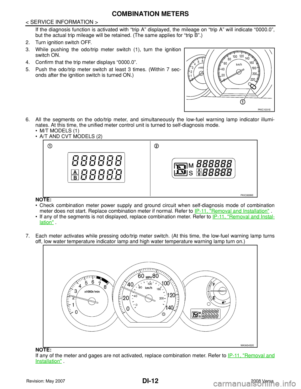
3. While pushing the odo/trip meter switch (1), turn the ignition
switch ON.
4. Confirm that the trip meter displays “0000.0”.
5. Push the odo/trip meter switch at least 3 times. (Within 7 sec-
onds after the ignition switch is turned ON.)
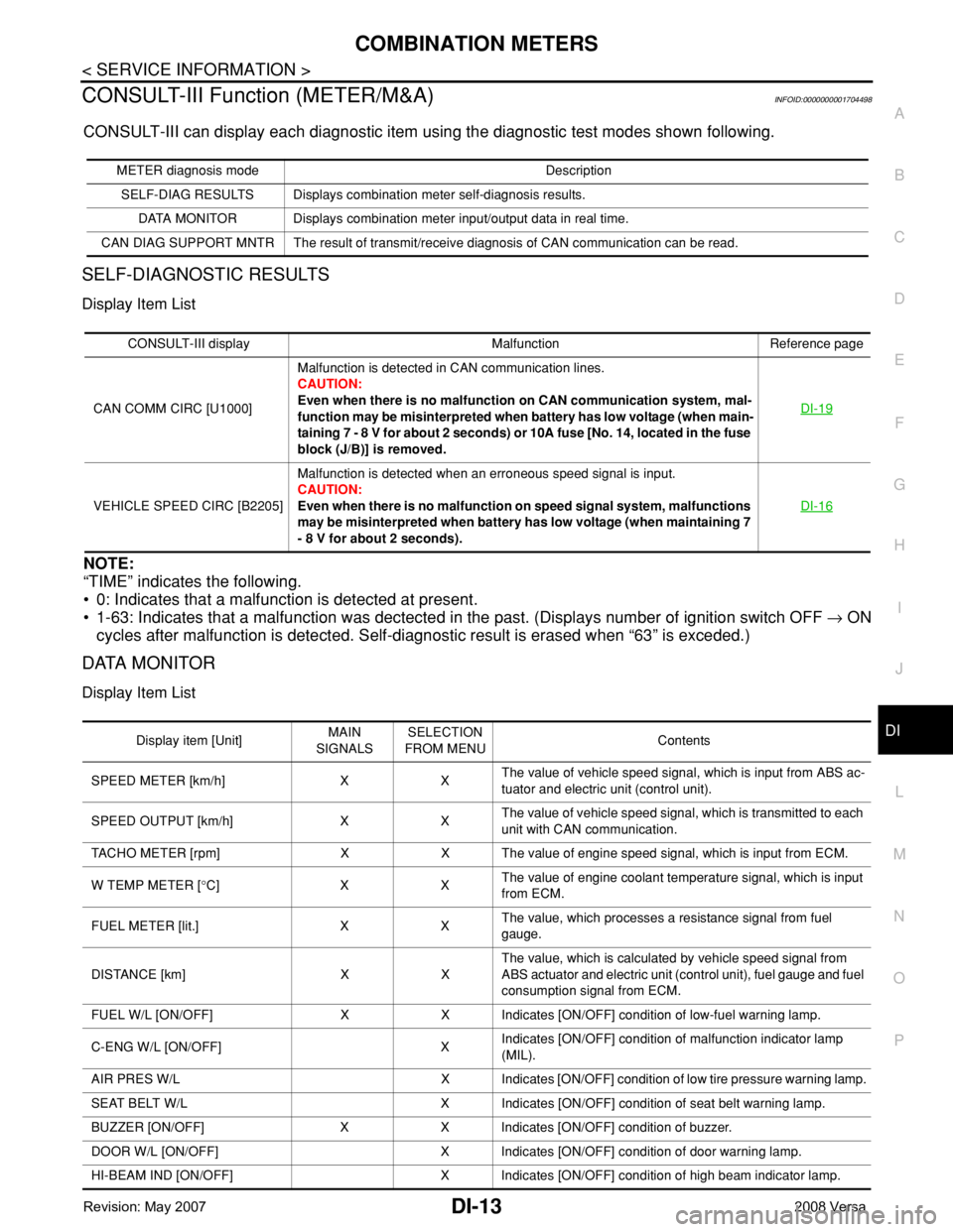
6. All the segments on the odo/trip meter, and simultaneously the low-fuel warning lamp indicator illumi-
nates. At this time, the unified meter control unit is turned to self-diagnosis mode.
• M/T MODELS (1)
• A/T AND CVT MODELS (2)
NOTE:
• Check combination meter power supply and ground circuit when self-diagnosis mode of combination
meter does not start. Replace combination meter if normal. Refer to IP-11, "
Removal and Installation" .
• If any of the segments is not displayed, replace combination meter. Refer to IP-11, "
Removal and Instal-
lation" .
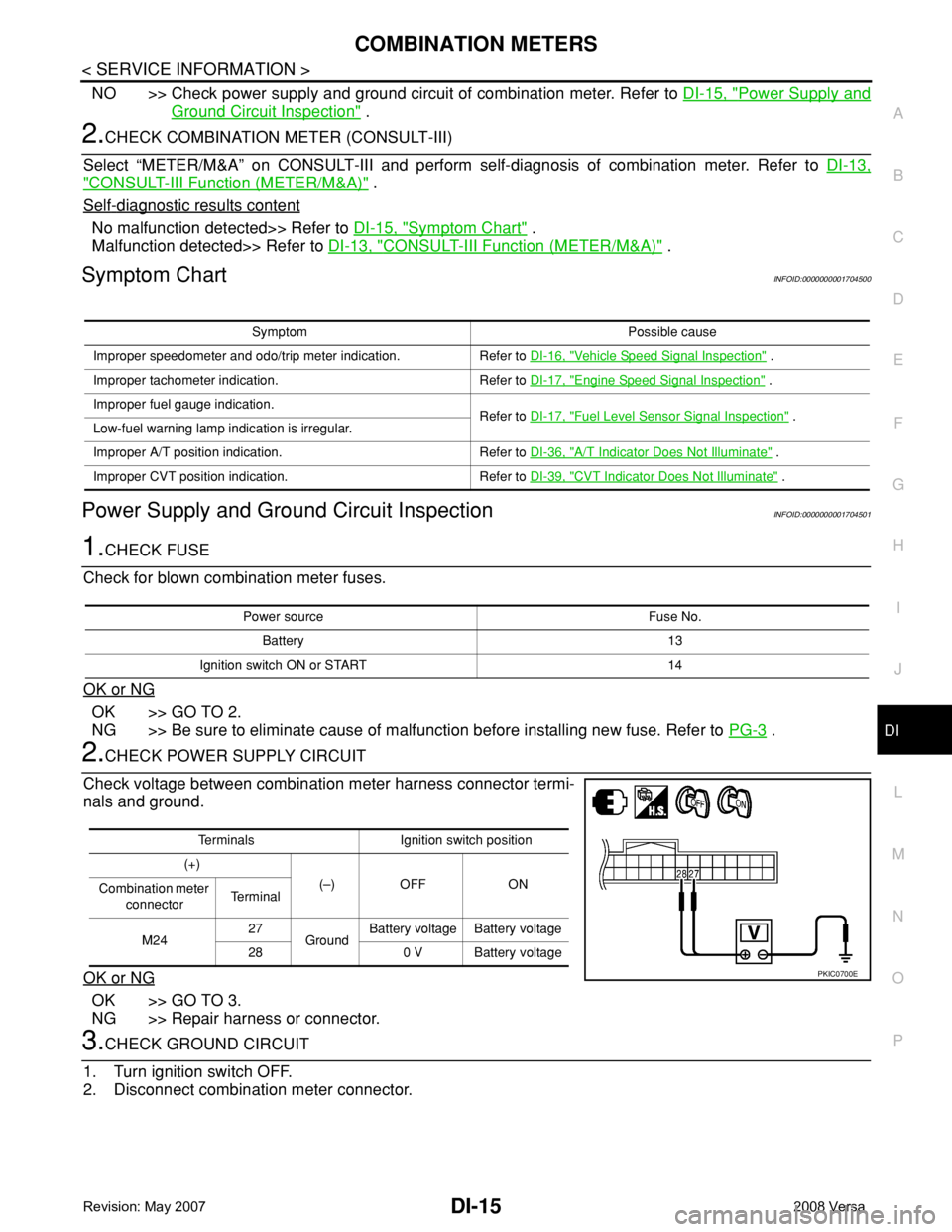
7. Each meter activates while pressing odo/trip meter switch. (At this time, the low-fuel warning lamp turns
off, low water temperature indicator lamp and high water temperature warning lamp turn on.)
NOTE:
If any of the meter and gages are not activated, replace combination meter. Refer to IP-11, "
Removal and
Installation" .
PKIC1031E
PKIC0699E
WKIA5452E
Page 1034 of 2771

COMBINATION METERS
DI-13
< SERVICE INFORMATION >
C
D
E
F
G
H
I
J
L
MA
B
DI
N
O
P
CONSULT-III Function (METER/M&A)INFOID:0000000001704498
CONSULT-III can display each diagnostic item using the diagnostic test modes shown following.
SELF-DIAGNOSTIC RESULTS
Display Item List
NOTE:
“TIME” indicates the following.
• 0: Indicates that a malfunction is detected at present.
• 1-63: Indicates that a malfunction was dectected in the past. (Displays number of ignition switch OFF → ON
cycles after malfunction is detected. Self-diagnostic result is erased when “63” is exceded.)
DATA MONITOR
Display Item List
METER diagnosis mode Description
SELF-DIAG RESULTS Displays combination meter self-diagnosis results.
DATA MONITOR Displays combination meter input/output data in real time.
CAN DIAG SUPPORT MNTR The result of transmit/receive diagnosis of CAN communication can be read.
CONSULT-III display Malfunction Reference page
CAN COMM CIRC [U1000]Malfunction is detected in CAN communication lines.
CAUTION:
Even when there is no malfunction on CAN communication system, mal-
function may be misinterpreted when battery has low voltage (when main-
taining 7 - 8 V for about 2 seconds) or 10A fuse [No. 14, located in the fuse
block (J/B)] is removed.DI-19
VEHICLE SPEED CIRC [B2205]Malfunction is detected when an erroneous speed signal is input.
CAUTION:
Even when there is no malfunction on speed signal system, malfunctions
may be misinterpreted when battery has low voltage (when maintaining 7
- 8 V for about 2 seconds).DI-16
Display item [Unit]MAIN
SIGNALSSELECTION
FROM MENUContents
SPEED METER [km/h] X XThe value of vehicle speed signal, which is input from ABS ac-
tuator and electric unit (control unit).
SPEED OUTPUT [km/h] X XThe value of vehicle speed signal, which is transmitted to each
unit with CAN communication.
TACHO METER [rpm] X X The value of engine speed signal, which is input from ECM.
W TEMP METER [°C] X XThe value of engine coolant temperature signal, which is input
from ECM.
FUEL METER [lit.] X XThe value, which processes a resistance signal from fuel
gauge.
DISTANCE [km] X XThe value, which is calculated by vehicle speed signal from
ABS actuator and electric unit (control unit), fuel gauge and fuel
consumption signal from ECM.
FUEL W/L [ON/OFF] X X Indicates [ON/OFF] condition of low-fuel warning lamp.
C-ENG W/L [ON/OFF] XIndicates [ON/OFF] condition of malfunction indicator lamp
(MIL).
AIR PRES W/L X Indicates [ON/OFF] condition of low tire pressure warning lamp.
SEAT BELT W/L X Indicates [ON/OFF] condition of seat belt warning lamp.
BUZZER [ON/OFF] X X Indicates [ON/OFF] condition of buzzer.
DOOR W/L [ON/OFF] X Indicates [ON/OFF] condition of door warning lamp.
HI-BEAM IND [ON/OFF] X Indicates [ON/OFF] condition of high beam indicator lamp.
Page 1035 of 2771

DI-14
< SERVICE INFORMATION >
COMBINATION METERS
NOTE:
Some items are not available due to vehicle specification.
*: The monitor will indicate “OFF” even though the brake warning lamp is on if either of the following conditions exist.
• The parking brake is engaged
• The brake fluid level is low
Trouble DiagnosisINFOID:0000000001704499
HOW TO PERFORM TROUBLE DIAGNOSIS
1. Confirm the symptom or customer complaint.
2. Perform preliminary check. Refer to "PRELIMINARY CHECK" .
3. According to the symptom chart, repair or replace the cause of the malfunction. Refer to DI-15, "
Symptom
Chart" .
4. Does the meter operate normally? If so, GO TO 5. If not, GO TO 2.
5. Inspection End.
PRELIMINARY CHECK
1.CHECK SELF-DIAGNOSIS OPERATION OF COMBINATION METER
Perform self-diagnosis of combination meter. Refer to DI-11, "
Self-Diagnosis Mode of Combination Meter" .
Does self
-diagnosis mode operate?
YES >> GO TO 2.
TURN IND [ON/OFF] X Indicates [ON/OFF] condition of turn indicator.
OIL W/L [ON/OFF] X Indicates [ON/OFF] condition of oil pressure warning lamp.
ABS W/L [ON/OFF] X Indicates [ON/OFF] condition of ABS warning lamp.
BRAKE W/L [ON/OFF] X Indicates [ON/OFF] condition of brake warning lamp.*
KEY G W/L [ON/OFF] X Indicates [ON/OFF] condition of KEY warning lamp (green).
KEY R W/L [ON/OFF] X Indicates [ON/OFF] condition of KEY warning lamp (red).
KEY KNOB W/L [ON/OFF] X Indicates [ON/OFF] condition of LOCK warning lamp.
PNP P SW [ON/OFF] X X Indicates [ON/OFF] condition of inhibitor P switch.
PNP N SW [ON/OFF] X X Indicates [ON/OFF] condition of inhibitor N switch.
O/D OFF SW [ON/OFF] X Indicates [ON/OFF] condition of O/D OFF switch.
BRAKE SW [ON/OFF] X Indicates [ON/OFF] condition of parking brake switch.
P RANGE IND [ON/OFF] X XIndicates [ON/OFF] condition of A/T or CVT shift P range indi-
cator.
R RANGE IND [ON/OFF] X XIndicates [ON/OFF] condition of A/T or CVT shift R range indi-
cator.
N RANGE IND [ON/OFF] X XIndicates [ON/OFF] condition of A/T or CVT shift N range indi-
cator.
D RANGE IND [ON/OFF] X XIndicates [ON/OFF] condition of A/T or CVT shift D range indi-
cator.
2 RANGE IND [ON/OFF] X X Indicates [ON/OFF] condition of A/T shift 2 range indicator.
L RANGE IND [ON/OFF] X X Indicates [ON/OFF] condition of CVT shift L range indicator.
1 RANGE IND [ON/OFF] X X Indicates [ON/OFF] condition of A/T shift 1 range indicator.
CRUISE IND [ON/OFF] X Indicates [ON/OFF] condition of CRUISE indicator.
SET IND [ON/OFF] X Indicates [ON/OFF] condition of SET indicator.
O/D OFF W/L [ON/OFF] X Indicates [ON/OFF] condition of O/D OFF indicator lamp.
e-4WD W/L [ON/OFF] X This item is not used for this model. “OFF” is always displayed.
EPS W/L [ON/OFF] X Indicates [ON/OFF] condition of EPS warning lamp. Display item [Unit]MAIN
SIGNALSSELECTION
FROM MENUContents
Page 1036 of 2771

COMBINATION METERS
DI-15
< SERVICE INFORMATION >
C
D
E
F
G
H
I
J
L
MA
B
DI
N
O
P
NO >> Check power supply and ground circuit of combination meter. Refer to DI-15, "Power Supply and
Ground Circuit Inspection" .
2.CHECK COMBINATION METER (CONSULT-III)
Select “METER/M&A” on CONSULT-III and perform self-diagnosis of combination meter. Refer to DI-13,
"CONSULT-III Function (METER/M&A)" .
Self
-diagnostic results content
No malfunction detected>> Refer to DI-15, "Symptom Chart" .
Malfunction detected>> Refer to DI-13, "
CONSULT-III Function (METER/M&A)" .
Symptom ChartINFOID:0000000001704500
Power Supply and Ground Circuit InspectionINFOID:0000000001704501
1.CHECK FUSE
Check for blown combination meter fuses.
OK or NG
OK >> GO TO 2.
NG >> Be sure to eliminate cause of malfunction before installing new fuse. Refer to PG-3
.
2.CHECK POWER SUPPLY CIRCUIT
Check voltage between combination meter harness connector termi-
nals and ground.
OK or NG
OK >> GO TO 3.
NG >> Repair harness or connector.
3.CHECK GROUND CIRCUIT
1. Turn ignition switch OFF.
2. Disconnect combination meter connector.
Symptom Possible cause
Improper speedometer and odo/trip meter indication. Refer to DI-16, "
Vehicle Speed Signal Inspection" .
Improper tachometer indication. Refer to DI-17, "
Engine Speed Signal Inspection" .
Improper fuel gauge indication.
Refer to DI-17, "
Fuel Level Sensor Signal Inspection" .
Low-fuel warning lamp indication is irregular.
Improper A/T position indication. Refer to DI-36, "
A/T Indicator Does Not Illuminate" .
Improper CVT position indication. Refer to DI-39, "
CVT Indicator Does Not Illuminate" .
Power source Fuse No.
Battery 13
Ignition switch ON or START 14
Terminals Ignition switch position
(+)
(–) OFF ON
Combination meter
connectorTe r m i n a l
M2427
GroundBattery voltage Battery voltage
28 0 V Battery voltage
PKIC0700E
Page 1055 of 2771
DI-34
< SERVICE INFORMATION >
A/T INDICATOR
A/T INDICATOR
System DescriptionINFOID:0000000001704515
The TCM receives A/T indicator signals from the park/neutral position (PNP) switch (R-range, D-range, 2-
range and 1-range) and the combination meter (P-range and N-range). The TCM then sends A/T position indi-
cator signals to the combination meter via CAN communication lines. The combination meter indicates the
received shift position.
PKIC0975E
Page 1056 of 2771
A/T INDICATOR
DI-35
< SERVICE INFORMATION >
C
D
E
F
G
H
I
J
L
MA
B
DI
N
O
P
Wiring Diagram - AT/IND -INFOID:0000000001704516
LKWA0360E
Page 1057 of 2771
DI-36
< SERVICE INFORMATION >
A/T INDICATOR
A/T Indicator Does Not Illuminate
INFOID:0000000001704517
1.CHECK SEGMENT OF A/T INDICATOR
LKWA0361E
Page 1058 of 2771

A/T INDICATOR
DI-37
< SERVICE INFORMATION >
C
D
E
F
G
H
I
J
L
MA
B
DI
N
O
P
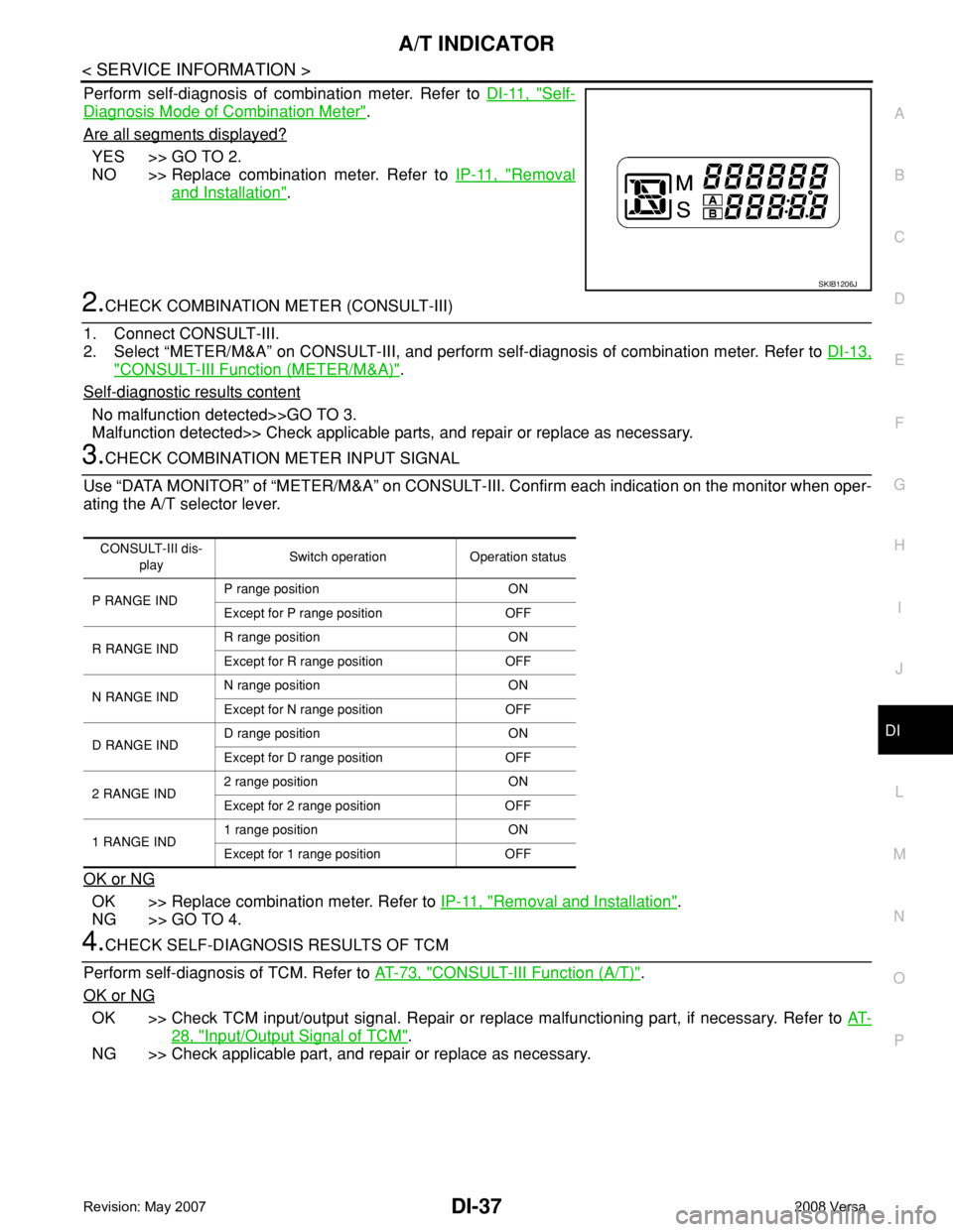
Perform self-diagnosis of combination meter. Refer to DI-11, "Self-
Diagnosis Mode of Combination Meter".
Are all segments displayed?
YES >> GO TO 2.
NO >> Replace combination meter. Refer to IP-11, "
Removal
and Installation".
2.CHECK COMBINATION METER (CONSULT-III)
1. Connect CONSULT-III.
2. Select “METER/M&A” on CONSULT-III, and perform self-diagnosis of combination meter. Refer to DI-13,
"CONSULT-III Function (METER/M&A)".
Self
-diagnostic results content
No malfunction detected>>GO TO 3.
Malfunction detected>> Check applicable parts, and repair or replace as necessary.
3.CHECK COMBINATION METER INPUT SIGNAL
Use “DATA MONITOR” of “METER/M&A” on CONSULT-III. Confirm each indication on the monitor when oper-
ating the A/T selector lever.
OK or NG
OK >> Replace combination meter. Refer to IP-11, "Removal and Installation".
NG >> GO TO 4.
4.CHECK SELF-DIAGNOSIS RESULTS OF TCM
Perform self-diagnosis of TCM. Refer to AT-73, "
CONSULT-III Function (A/T)".
OK or NG
OK >> Check TCM input/output signal. Repair or replace malfunctioning part, if necessary. Refer to AT-
28, "Input/Output Signal of TCM".
NG >> Check applicable part, and repair or replace as necessary.
SKIB1206J
CONSULT-III dis-
playSwitch operation Operation status
P RANGE INDP range position ON
Except for P range position OFF
R RANGE INDR range position ON
Except for R range position OFF
N RANGE INDN range position ON
Except for N range position OFF
D RANGE INDD range position ON
Except for D range position OFF
2 RANGE IND2 range position ON
Except for 2 range position OFF
1 RANGE IND1 range position ON
Except for 1 range position OFF