2008 NISSAN LATIO door lock
[x] Cancel search: door lockPage 633 of 2771
VEHICLE SECURITY (THEFT WARNING) SYSTEM
BL-199
< SERVICE INFORMATION >
C
D
E
F
G
H
J
K
L
MA
B
BL
N
O
P
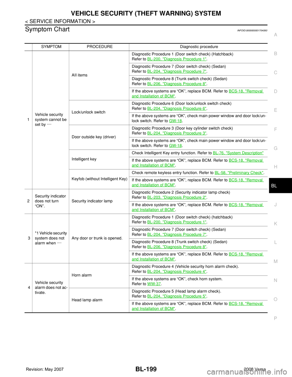
Symptom ChartINFOID:0000000001704093
SYMPTOM PROCEDURE Diagnostic procedure
1Vehicle security
system cannot be
set by ····AII itemsDiagnostic Procedure 1 (Door switch check) (Hatchback)
Refer to BL-200, "
Diagnosis Procedure 1".
Diagnostic Procedure 7 (Door switch check) (Sedan)
Refer to BL-204, "
Diagnosis Procedure 7".
Diagnostic Procedure 8 (Trunk switch check) (Sedan)
Refer to BL-206, "
Diagnosis Procedure 8".
If the above systems are “OK”, replace BCM. Refer to BCS-18, "
Removal
and Installation of BCM".
Lock/unlock switchDiagnostic Procedure 6 (Door lock/unlock switch check)
Refer to BL-204, "
Diagnosis Procedure 6".
If the above systems are “OK”, check main power window and door lock/un-
lock switch. Refer to GW-18
.
Door outside key (driver)Diagnostic Procedure 3 (Door key cylinder switch check)
Refer to BL-204, "
Diagnosis Procedure 3".
If the above systems are “OK”, check main power window and door lock/un-
lock switch. Refer to GW-18
.
Intelligent keyCheck Intelligent Key entry function. Refer to BL-76, "
System Description"
If the above systems are “OK”, replace BCM. Refer to BCS-18, "Removal
and Installation of BCM".
Keyfob (without Intelligent Key)Check remote keyless entry function. Refer to BL-58, "
Preliminary Check".
If the above systems are “OK”, replace BCM. Refer to BCS-18, "
Removal
and Installation of BCM".
2Security indicator
does not turn
“ON”.Security indicator lampDiagnostic Procedure 2 (Security indicator lamp check)
Refer to BL-203, "
Diagnosis Procedure 2".
If the above systems are “OK”, replace BCM. Refer to BCS-18, "
Removal
and Installation of BCM".
3*1 Vehicle security
system does not
alarm when ····Any door or trunk is opened.Diagnostic Procedure 1 (Door switch check) (hatchback)
Refer to BL-200, "
Diagnosis Procedure 1".
Diagnostic Procedure 7 (Door switch check) (Sedan)
Refer to BL-204, "
Diagnosis Procedure 7".
Diagnostic Procedure 8 (Trunk switch check) (Sedan)
Refer to BL-206, "
Diagnosis Procedure 8".
If the above systems are “OK”, replace BCM. Refer to BCS-18, "
Removal
and Installation of BCM".
4Vehicle security
alarm does not ac-
tivate.Horn alarmDiagnostic Procedure 4 (Vehicle security horn alarm check).
Refer to BL-204, "
Diagnosis Procedure 4".
If the above systems are “OK”, check horn system.
Refer to WW-37
.
Head lamp alarmDiagnostic Procedure 5 (Head lamp alarm check).
Refer to BL-204, "
Diagnosis Procedure 5".
If the above systems are “OK”, replace BCM. Refer to BCS-18, "
Removal
and Installation of BCM".
Page 634 of 2771
BL-200
< SERVICE INFORMATION >
VEHICLE SECURITY (THEFT WARNING) SYSTEM
*1 : Make sure the system is in the armed phase.
Diagnosis Procedure 1INFOID:0000000001704094
1-1 DOOR SWITCH CHECK (HATCHBACK)
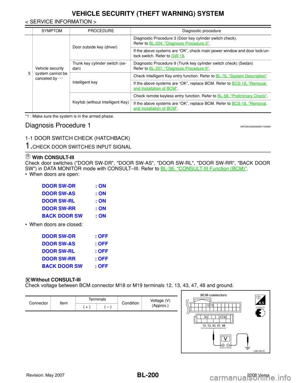
1.CHECK DOOR SWITCHES INPUT SIGNAL
With CONSULT-III
Check door switches ("DOOR SW-DR", "DOOR SW-AS", "DOOR SW-RL", "DOOR SW-RR", "BACK DOOR
SW") in DATA MONITOR mode with CONSULT–III. Refer to BL-36, "
CONSULT-III Function (BCM)".
• When doors are open:
• When doors are closed:
Without CONSULT-III
Check voltage between BCM connector M18 or M19 terminals 12, 13, 43, 47, 48 and ground.
5Vehicle security
system cannot be
canceled by ····Door outside key (driver)Diagnostic Procedure 3 (Door key cylinder switch check).
Refer to BL-204, "
Diagnosis Procedure 3".
If the above systems are “OK”, check main power window and door lock/un-
lock switch. Refer to GW-18
.
Trunk key cylinder switch (se-
dan)Diagnostic Procedure 9 (Trunk key cylinder switch check) (Sedan)
Refer to BL-207, "
Diagnosis Procedure 9".
Intelligent keyCheck Intelligent Key entry function. Refer to BL-76, "
System Description"
If the above systems are “OK”, replace BCM. Refer to BCS-18, "Removal
and Installation of BCM".
Keyfob (without Intelligent Key)Check remote keyless entry function. Refer to BL-58, "
Preliminary Check".
If the above systems are “OK”, replace BCM. Refer to BCS-18, "
Removal
and Installation of BCM". SYMPTOM PROCEDURE Diagnostic procedure
DOOR SW-DR : ON
DOOR SW-AS : ON
DOOR SW-RL : ON
DOOR SW-RR : ON
BACK DOOR SW : ON
DOOR SW-DR : OFF
DOOR SW-AS : OFF
DOOR SW-RL : OFF
DOOR SW-RR : OFF
BACK DOOR SW : OFF
Connector ItemTe r m i n a l s
ConditionVoltage (V)
(Approx.)
( + ) ( – )
LIIA1041E
Page 635 of 2771
VEHICLE SECURITY (THEFT WARNING) SYSTEM
BL-201
< SERVICE INFORMATION >
C
D
E
F
G
H
J
K
L
MA
B
BL
N
O
P
OK or NG
OK1 >> Door switch circuit is OK (without Intelligent Key).
OK2 >> GO TO 6 (with Intelligent Key).
NG >> GO TO 2.
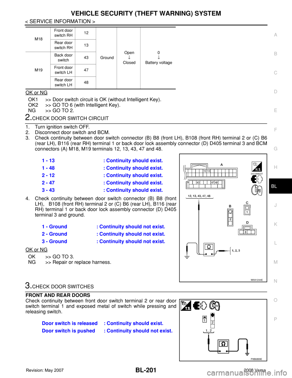
2.CHECK DOOR SWITCH CIRCUIT
1. Turn ignition switch OFF.
2. Disconnect door switch and BCM.
3. Check continuity between door switch connector (B) B8 (front LH), B108 (front RH) terminal 2 or (C) B6
(rear LH), B116 (rear RH) terminal 1 or back door lock assembly connector (D) D405 terminal 3 and BCM
connectors (A) M18, M19 terminals 12, 13, 43, 47 and 48.
4. Check continuity between door switch connector (B) B8 (front
LH), B108 (front RH) terminal 2 or (C) B6 (rear LH), B116 (rear
RH) terminal 1 or back door lock assembly connector (D) D405
terminal 3 and ground.
OK or NG
OK >> GO TO 3.
NG >> Repair or replace harness.
3.CHECK DOOR SWITCHES
FRONT AND REAR DOORS
Check continuity between front door switch terminal 2 or rear door
switch terminal 1 and exposed metal of switch while pressing and
releasing switch.
M18Front door
switch RH12
GroundOpen
↓
Closed0
↓
Battery voltage Rear door
switch RH13
M19Back door
switch43
Front door
switch LH47
Rear door
switch LH48
1 - 13 : Continuity should exist.
1 - 48 : Continuity should exist.
2 - 12 : Continuity should exist.
2 - 47 : Continuity should exist.
3 - 43 : Continuity should exist.
1 - Ground : Continuity should not exist.
2 - Ground : Continuity should not exist.
3 - Ground : Continuity should not exist.
WIIA1244E
Door switch is released : Continuity should exist.
Door switch is pushed : Continuity should not exist.
PIIB6899E
Page 636 of 2771
BL-202
< SERVICE INFORMATION >
VEHICLE SECURITY (THEFT WARNING) SYSTEM
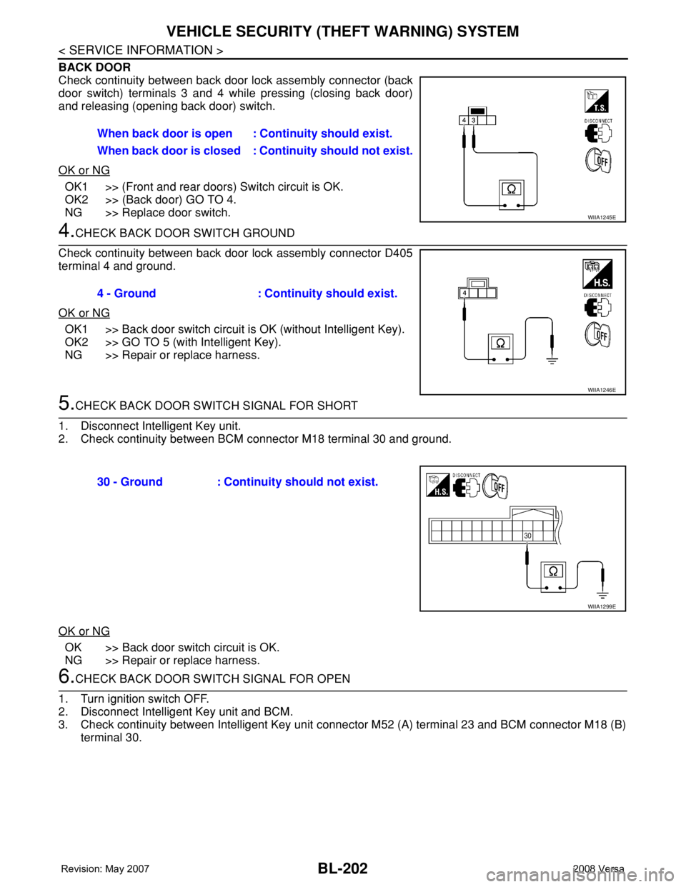
BACK DOOR
Check continuity between back door lock assembly connector (back
door switch) terminals 3 and 4 while pressing (closing back door)
and releasing (opening back door) switch.
OK or NG
OK1 >> (Front and rear doors) Switch circuit is OK.
OK2 >> (Back door) GO TO 4.
NG >> Replace door switch.
4.CHECK BACK DOOR SWITCH GROUND
Check continuity between back door lock assembly connector D405
terminal 4 and ground.
OK or NG
OK1 >> Back door switch circuit is OK (without Intelligent Key).
OK2 >> GO TO 5 (with Intelligent Key).
NG >> Repair or replace harness.
5.CHECK BACK DOOR SWITCH SIGNAL FOR SHORT
1. Disconnect Intelligent Key unit.
2. Check continuity between BCM connector M18 terminal 30 and ground.
OK or NG
OK >> Back door switch circuit is OK.
NG >> Repair or replace harness.
6.CHECK BACK DOOR SWITCH SIGNAL FOR OPEN
1. Turn ignition switch OFF.
2. Disconnect Intelligent Key unit and BCM.
3. Check continuity between Intelligent Key unit connector M52 (A) terminal 23 and BCM connector M18 (B)
terminal 30.When back door is open : Continuity should exist.
When back door is closed : Continuity should not exist.
WIIA1245E
4 - Ground : Continuity should exist.
WIIA1246E
30 - Ground : Continuity should not exist.
WIIA1299E
Page 638 of 2771
BL-204
< SERVICE INFORMATION >
VEHICLE SECURITY (THEFT WARNING) SYSTEM
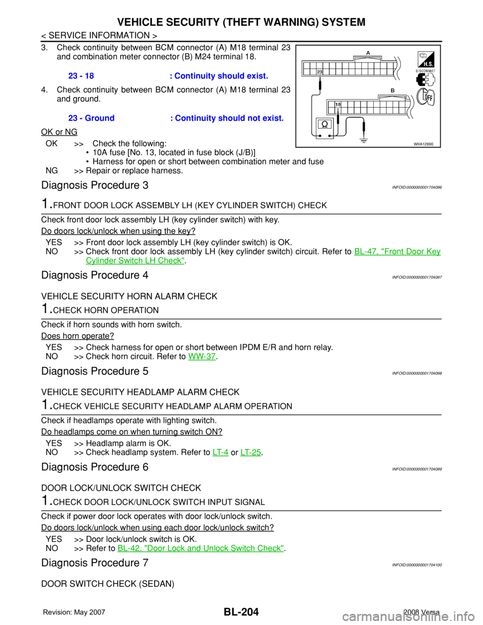
3. Check continuity between BCM connector (A) M18 terminal 23
and combination meter connector (B) M24 terminal 18.
4. Check continuity between BCM connector (A) M18 terminal 23
and ground.
OK or NG
OK >> Check the following:
• 10A fuse [No. 13, located in fuse block (J/B)]
• Harness for open or short between combination meter and fuse
NG >> Repair or replace harness.
Diagnosis Procedure 3INFOID:0000000001704096
1.FRONT DOOR LOCK ASSEMBLY LH (KEY CYLINDER SWITCH) CHECK
Check front door lock assembly LH (key cylinder switch) with key.
Do doors lock/unlock when using the key?
YES >> Front door lock assembly LH (key cylinder switch) is OK.
NO >> Check front door lock assembly LH (key cylinder switch) circuit. Refer to BL-47, "
Front Door Key
Cylinder Switch LH Check".
Diagnosis Procedure 4INFOID:0000000001704097
VEHICLE SECURITY HORN ALARM CHECK
1.CHECK HORN OPERATION
Check if horn sounds with horn switch.
Does horn operate?
YES >> Check harness for open or short between IPDM E/R and horn relay.
NO >> Check horn circuit. Refer to WW-37
.
Diagnosis Procedure 5INFOID:0000000001704098
VEHICLE SECURITY HEADLAMP ALARM CHECK
1.CHECK VEHICLE SECURITY HEADLAMP ALARM OPERATION
Check if headlamps operate with lighting switch.
Do headlamps come on when turning switch ON?
YES >> Headlamp alarm is OK.
NO >> Check headlamp system. Refer to LT- 4
or LT- 2 5.
Diagnosis Procedure 6INFOID:0000000001704099
DOOR LOCK/UNLOCK SWITCH CHECK
1.CHECK DOOR LOCK/UNLOCK SWITCH INPUT SIGNAL
Check if power door lock operates with door lock/unlock switch.
Do doors lock/unlock when using each door lock/unlock switch?
YES >> Door lock/unlock switch is OK.
NO >> Refer to BL-42, "
Door Lock and Unlock Switch Check".
Diagnosis Procedure 7INFOID:0000000001704100
DOOR SWITCH CHECK (SEDAN)
23 - 18 : Continuity should exist.
23 - Ground : Continuity should not exist.
WIIA1269E
Page 1034 of 2771
COMBINATION METERS
DI-13
< SERVICE INFORMATION >
C
D
E
F
G
H
I
J
L
MA
B
DI
N
O
P
CONSULT-III Function (METER/M&A)INFOID:0000000001704498
CONSULT-III can display each diagnostic item using the diagnostic test modes shown following.
SELF-DIAGNOSTIC RESULTS
Display Item List
NOTE:
“TIME” indicates the following.
• 0: Indicates that a malfunction is detected at present.
• 1-63: Indicates that a malfunction was dectected in the past. (Displays number of ignition switch OFF → ON
cycles after malfunction is detected. Self-diagnostic result is erased when “63” is exceded.)
DATA MONITOR
Display Item List
METER diagnosis mode Description
SELF-DIAG RESULTS Displays combination meter self-diagnosis results.
DATA MONITOR Displays combination meter input/output data in real time.
CAN DIAG SUPPORT MNTR The result of transmit/receive diagnosis of CAN communication can be read.
CONSULT-III display Malfunction Reference page
CAN COMM CIRC [U1000]Malfunction is detected in CAN communication lines.
CAUTION:
Even when there is no malfunction on CAN communication system, mal-
function may be misinterpreted when battery has low voltage (when main-
taining 7 - 8 V for about 2 seconds) or 10A fuse [No. 14, located in the fuse
block (J/B)] is removed.DI-19
VEHICLE SPEED CIRC [B2205]Malfunction is detected when an erroneous speed signal is input.
CAUTION:
Even when there is no malfunction on speed signal system, malfunctions
may be misinterpreted when battery has low voltage (when maintaining 7
- 8 V for about 2 seconds).DI-16
Display item [Unit]MAIN
SIGNALSSELECTION
FROM MENUContents
SPEED METER [km/h] X XThe value of vehicle speed signal, which is input from ABS ac-
tuator and electric unit (control unit).
SPEED OUTPUT [km/h] X XThe value of vehicle speed signal, which is transmitted to each
unit with CAN communication.
TACHO METER [rpm] X X The value of engine speed signal, which is input from ECM.
W TEMP METER [°C] X XThe value of engine coolant temperature signal, which is input
from ECM.
FUEL METER [lit.] X XThe value, which processes a resistance signal from fuel
gauge.
DISTANCE [km] X XThe value, which is calculated by vehicle speed signal from
ABS actuator and electric unit (control unit), fuel gauge and fuel
consumption signal from ECM.
FUEL W/L [ON/OFF] X X Indicates [ON/OFF] condition of low-fuel warning lamp.
C-ENG W/L [ON/OFF] XIndicates [ON/OFF] condition of malfunction indicator lamp
(MIL).
AIR PRES W/L X Indicates [ON/OFF] condition of low tire pressure warning lamp.
SEAT BELT W/L X Indicates [ON/OFF] condition of seat belt warning lamp.
BUZZER [ON/OFF] X X Indicates [ON/OFF] condition of buzzer.
DOOR W/L [ON/OFF] X Indicates [ON/OFF] condition of door warning lamp.
HI-BEAM IND [ON/OFF] X Indicates [ON/OFF] condition of high beam indicator lamp.
Page 1062 of 2771
WARNING CHIME
DI-41
< SERVICE INFORMATION >
C
D
E
F
G
H
I
J
L
MA
B
DI
N
O
P
WARNING CHIME
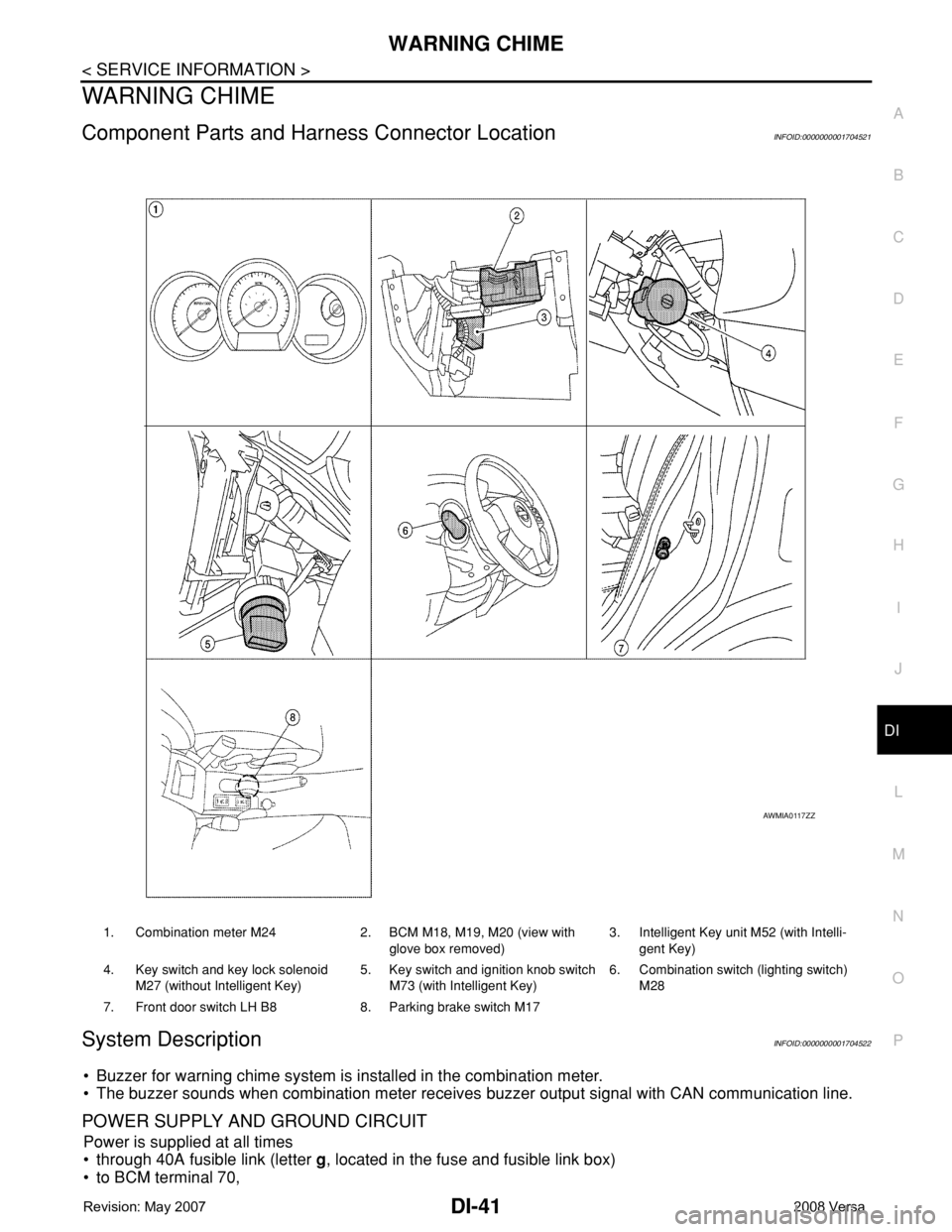
Component Parts and Harness Connector LocationINFOID:0000000001704521
System DescriptionINFOID:0000000001704522
• Buzzer for warning chime system is installed in the combination meter.
• The buzzer sounds when combination meter receives buzzer output signal with CAN communication line.
POWER SUPPLY AND GROUND CIRCUIT
Power is supplied at all times
• through 40A fusible link (letter g, located in the fuse and fusible link box)
• to BCM terminal 70,
1. Combination meter M24 2. BCM M18, M19, M20 (view with
glove box removed)3. Intelligent Key unit M52 (with Intelli-
gent Key)
4. Key switch and key lock solenoid
M27 (without Intelligent Key)5. Key switch and ignition knob switch
M73 (with Intelligent Key)6. Combination switch (lighting switch)
M28
7. Front door switch LH B8 8. Parking brake switch M17
AWMIA0117ZZ
Page 1063 of 2771
![NISSAN LATIO 2008 Service Repair Manual DI-42
< SERVICE INFORMATION >
WARNING CHIME
• through 10A fuse [No. 8, located in the fuse block (J/B)]
• to BCM terminal 57,
• through 10A fuse [No. 13, located in the fuse block (J/B)]
• to NISSAN LATIO 2008 Service Repair Manual DI-42
< SERVICE INFORMATION >
WARNING CHIME
• through 10A fuse [No. 8, located in the fuse block (J/B)]
• to BCM terminal 57,
• through 10A fuse [No. 13, located in the fuse block (J/B)]
• to](/manual-img/5/57360/w960_57360-1062.png)
DI-42
< SERVICE INFORMATION >
WARNING CHIME
• through 10A fuse [No. 8, located in the fuse block (J/B)]
• to BCM terminal 57,
• through 10A fuse [No. 13, located in the fuse block (J/B)]
• to combination meter terminal 27.
With ignition switch in the ON or START position, power is supplied
• through 10A fuse [No. 6, located in the fuse block (J/B)]
• to BCM terminal 38,
• through 10A fuse [No. 3, located in the fuse block (J/B)]
• to combination meter terminal 28.
Ground is supplied
• to BCM terminal 67 and
• to combination meter terminals 21, 22 and 23
• through grounds M57 and M61.
IGNITION KEY WARNING CHIME (WITHOUT INTELLIGENT KEY)
With the key inserted into the key switch, and the ignition switch in the OFF or ACC position, when driver's
door is opened, the warning chime will sound.
• BCM detects key inserted into the ignition switch, and sends key warning signal to combination meter with
CAN communication line.
• When combination meter receives key warning signal, it sounds warning chime.
IGNITION KEY WARNING CHIME (WITH INTELLIGENT KEY)
When Mechanical Key Is Used
With the key inserted into the key switch, and the ignition switch in the LOCK or ACC position, when driver's
door is opened, the warning chime will sound.
• BCM detects key inserted into the ignition switch, and sends key warning signal to combination meter with
CAN communication line.
• When combination meter receives key warning signal, it sounds warning chime.
When Intelligent Key Is Carried With The Driver
Refer to BL-76, "System Description".
LIGHT WARNING CHIME
The warning chime sounds, when driver's door is opened (door switch ON) with lighting switch ON and the
ignition switch is in any position other than ON or START.
NOTE:
BCM detected lighting switch in the 1st or 2nd position, refer to LT-62, "
Combination Switch Reading Func-
tion".
• BCM detects headlamps are illuminated, and sends light warning signal to combination meter with CAN
communication lines.
WKIA5463E
WKIA5464E