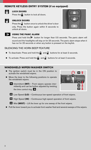
Page 9 of 20
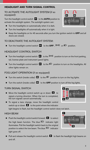
 for
5 seconds. Pressing the button again during this 5-second period will stop scan tuning
and the ra")
SCAN/RPT BUTTON
Press the SCAN/RPT button to stop at each broadcasting station (FM, AM or XM �) for
5 seconds. Pressing the button again during this 5-second period will stop scan tuning
and the radio will remain tuned to that station. If the SCAN/RPTbutton is not pressed
within 5 seconds, scan tuning moves to the next station.
CAT/FOLDER BUTTON
� To manually tune the radio, press the CAT/FOLDERbutton.
� When the CAT/FOLDER button is pressed while a CD is playing, it will fast forward
or rewind. When the button is released, the CD will play at normal speed.
� MP3 PLAYBACK (if so equipped)
In addition to playing audio CDs, the audio system can play MP3 files recorded on
CD-ROM, CD-R, and CD-RW discs. Each disc can have a maximum of 8 folder levels
and 255 folders. A total of 512 MP3 files can be played back. During MP3 playback,
some recorded ID3 tag information can be displayed by pressing the DISP CLOCK
button. Use the CAT/FOLDERbutton to navigate the MP3 folders.
EJECT BUTTON
� EJECT A SINGLE DISC - Press the
button for less than 1.5 seconds. Select the
eject slot by pressing the CD insert select button ( 1-6 ) . The CD will then eject.
� EJECT ALL DISCS - Press and hold the
button for more than 1.5 seconds. The
CDs will be ejected one after another.
TUNING AND AUDIO CONTROL KNOB
To manually tune the radio, turn the TUNEknob. To adjust the Bass, Midrange, Treble,
Fade, Balance, and Speed Sensitive Volume (SSV) (if so equipped) , press the AUDIO
knob until the desired mode appears in the display. Then turn the TUNEknob to adjust
to the desired level.
STATION AND CD SELECT BUTTONS
� To store a station in a preset you must first select A, B, or C memory bank by pressing
the PRESET A·B·Cbutton andtune tothe desired FM,AMorXM �station. Then
press andhold thedesired stationselectbutton foratleast 2seconds. Whenthe
preset indicator illuminates, a beep will sound, indicating memorization is complete.
To retrieve a previously set station, select the memory bank where the preset was set,
then press the corresponding station select button.
� While playing a CD, to select a different CD loaded into the CD changer; press one
of the CD select buttons ( 1-6 ).
7
Page 10 of 20
 , then insert the CD.
� LOAD UP TO 6")
LOAD BUTTON
� LOAD A SINGLE DISC - Press the
button for less than 1.5 seconds. Select the
loading slot by pressing one of the CD insert select button ( 1-6 ) , then insert the CD.
� LOAD UP TO 6 DISCS - Press and hold the
button for more than 1.5 seconds.
The slot numbers (1-6) will illuminate on the display when CDs are loaded into the
changer.
*XM � Satellite Radioisonly available onvehicles equipped withoptional XM�satellite
subscription service.
CLOCK SET/ADJUSTMENT
� Press and hold the DISP CLOCKbutton until it beeps. The hours will start flashing.
� Press the CAT/FOLDER orSEEK/TRACK button to adjust the hours.
� Press the DISP CLOCK button to switch to the minute adjustment.
� Press the CAT/FOLDER orSEEK/TRACK button to adjust the minutes.
� Press the DISP CLOCK button to store the time and exit clock set mode.
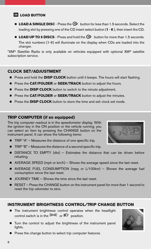
TRIP COMPUTER (if so equipped)
The trip computer readout is in the speedometer display. With
theignition keyinthe ON position orthe vehicle running, you
can select anitem bypressing theCHANGE buttononthe
instrument panel. It can show the following items:
� TRIP “A” – Measures the distance of one specific trip.
� TRIP “B” – Measures the distance of a second specific trip.
� DISTANCE TOEMPTY (dte)–Estimates thedistance thatcanbedriven before
refueling.
� AVERAGE SPEED (mph or km/h) – Shows the average speed since the last reset.
� AVERAGE FUELCONSUMPTION (mpgorL/100km) –Shows theaverage fuel
consumption since the last reset.
� JOURNEY TIME – Shows the time since the last reset.
� RESET – Press the CHANGE button on the instrument panel for more than 1 second to
reset the trip odometer to zero.
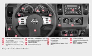
INSTRUMENT BRIGHTNESS CONTROL/TRIP CHANGE BUTTON
� The instrument brightness controloperates whentheheadlight
control switch is in the
orposition.
� Turn thecontrol toadjust thebrightness ofthe instrument panel
lights.
� Press the change button to select trip computer features.
8
Page 11 of 20
 SHIFT SWITCH (if so equipped)
�This system provides three positions so the driver can select
the desired drive mode according to driving conditions.
� 2WD – Dry, paved road")
FOUR-WHEEL DRIVE (4WD) SHIFT SWITCH (if so equipped)
�This system provides three positions so the driver can select
the desired drive mode according to driving conditions.
� 2WD – Dry, paved roads.
� 4H –Rocky, sandyorsnow-covered roads.(Before placing
4WD shiftswitch in4H position from2WD, ensure vehicle
speed is less than 62.5 MPH [100 km/h]) .
� 4LO – When maximum power and traction are required (steep
grades, rocky, sandy or muddy roads) .
NOTE: The vehicle must be stopped and in N (Neutral) with the brake pedal depressed when
shifting into and out of 4LO.
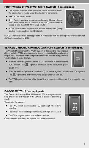
VEHICLE DYNAMIC CONTROL (VDC) OFF SWITCH (if so equipped)
The Vehicle Dynamic Control (VDC) system is designed to help improve
driving stability. VDC detects wheel spin and controls braking and engine
output. VDC may need to be temporarily shut off if you are trying to free a
vehicle stuck in snow or mud.
� Push the Vehicle Dynamic Control (VDC) off switch to deactivate the
VDC system. The
lightwillilluminate inthe instrument panel
gauge area.
� Push the Vehicle Dynamic Control (VDC) off switch again to activate the VDC system.
The
light in the instrument panel gauge area will turn off.
� The VDC system is active while the vehicle is running until the switch is pressed to turn
it off.
E-LOCK SWITCH (if so equipped)
The Electronic LockingRearDifferential (E-Lock)systemcan
help provide addedtraction ifthe vehicle isstuck orbecoming
stuck.
To activate the system:
� The 4WD switch must be in the 4LO position (4-wheel drive
vehicles) ,
� The vehicle must be stopped or moving at 4 mph or less, and
� The E-Lock system switch must be turned on.
Once the vehicle is free, the system should be turned off.
9
Page 12 of 20

Thehilldescent controlsystem isdesigned toreduce driver
workload when going down steep hills. The hill descent control
system helps to control vehicle spe")
HILL DESCENT CONTROL SWITCH (if so equipped)
Thehilldescent controlsystem isdesigned toreduce driver
workload when going down steep hills. The hill descent control
system helps to control vehicle speed so the driver can concen-
trate on steering the vehicle.
To activate the hill descent control system:
� The automatic transmission selectorlevermust beinfor-
ward or reverse gear,
� The 4WD switch must be in the 4L position and the vehicle
speed must be under 15 MPH (25 km/h) , or
� The 4WD switch must be in the 4H position and the vehicle speed must be under 21
MPH (35 km/h) , and
� The hill descent control system switch must be on.
� The hill descent control indicator light will come on when the system is activated. Also,
the stop/tail lights illuminate while the hill descent control system applies the brakes to
control vehicle speed. To turn off the hill descent control system, push the switch to the
off position. The hill descent control system is temporarily disabled when the brake or
accelerator pedal is depressed.
HILL START ASSIST (if so equipped)
The hill start assist system automatically keeps the brakes applied to help prevent the vehicle
from rolling backwards in the time it takes the driver to release the brake pedal and apply the
accelerator when the vehicle is stopped on a hill.
Hill start assist will operate automatically under the following conditions:
� The selector lever is shifted to a forward or reverse gear.
� The vehicle is stopped completely on a hill by applying the brake.
The maximum holding time is 2 seconds.
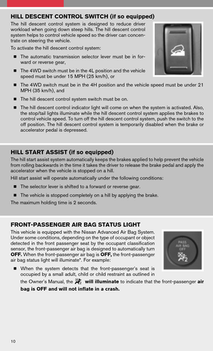
FRONT-PASSENGER AIR BAG STATUS LIGHT
This vehicle is equipped with the Nissan Advanced Air Bag System.
Under some conditions, depending on the type of occupant or object
detected inthe front passenger seatbythe occupant classification
sensor, the front-passenger air bag is designed to automatically turn
OFF. When the front-passenger air bag is OFF,the front-passenger
air bag status light will illuminate*. For example:
� When thesystem detects thatthefront-passenger’s seatis
occupied by a small adult, child or child restraint as outlined in
the Owner’s Manual, the
will illuminate to indicate that the front-passenger air
bag is OFF and will not inflate in a crash.
10
Page 13 of 20

�When the front-passenger’s seat is occupied and the passenger meets the conditions
outlined inthe Owner’s Manual,the
willnotilluminate toindicate thatthe
front-passenger air bag is operational.
*When thesystem detects thatthefront-passenger’s seatisunoccupied, the
passenger air bag status light will not illuminate even though the front-passenger
air bag is OFF.
TIRE PRESSURE MONITORING SYSTEM (TPMS)
This system monitors tirepressure. Ifthe low tirepressure warning
light illuminates, check the tire pressure in all four tires.
Adjust the low tire pressure to the recommended COLD tire pressure
shown on the Tire and Loading Information label located in the driver’s
door opening. After tire pressures are adjusted, the vehicle will need
to be driven at speeds above 16 MPH (25 km/h) to activate the TPMS
and turn off the low tire pressure warning light.
SEAT BELT WARNING LIGHT AND CHIME
� The light and chime remind you to fasten your seat belts. The light
illuminates whenevertheignition keyisturned tothe ON or
START position andremains illuminated untilthedriver’s seat
belt is fastened. At the same time, the chime sounds for approxi-
mately 6seconds unlessthedriver’s seatbeltissecurely fas-
tened.
� The seat beltwarning lightmayalso illuminate ifthe front pas-
senger’s seatbeltisnot fastened whenthefront passenger’s
seat is occupied (if so equipped) . For 7 seconds after the ignition switch is in the ON
position, the system does not activate the warning light for the front passenger.
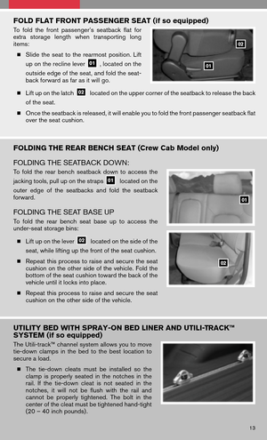
CHILD SAFETY REAR DOOR LOCK (Crew Cab model only)
Child safety locks help prevent the rear doors from being opened acci-
dentally, especially when small children are in the vehicle. The child safety
lock levers are located on the edge of the rear doors. When the lever is in
the LOCK position, the door can only be opened from the outside.
11
Page 14 of 20

The ignition switch must be in the ON position to operate the
moonroof controls.
TILTING THE MOONROOF
� To tiltthe moonroof up,first close themoonroof by
pushing t")
MOONROOF CONTROLS (if so equipped)
The ignition switch must be in the ON position to operate the
moonroof controls.
TILTING THE MOONROOF
� To tiltthe moonroof up,first close themoonroof by
pushing theswitch toward UP/CLOSE
.Release
the switch, then push the UP/CLOSEswitch again to tilt
the moonroof up.
� To tiltthe moonroof down,pushtheswitch toward
DOWN/OPEN
.
SLIDING THE MOONROOF
� To fully open the moonroof, push the switch toward DOWN/OPEN. To open the
moonroof part way, push the switch in any direction while the moonroof is sliding to stop
it in the desired position.
� To fully close themoonroof, pushtheswitch toward UP/CLOSE
.To close the
moonroof part way, push the switch in any direction while the moonroof is sliding to stop
it in the desired position.
FRONT SEAT ADJUSTMENTS
With manual seats (if so equipped):
� Pull uponthe lever under thefront ofthe
seat and slide backward or forward; release.
� Lift the lever
on the side of the seat to
adjust yourseatback forwardorbackward;
release when you have found a comfortable
angle and the seat belt fits properly.
� Turn either dial
to adjust the angle and
height of the seat cushion to the desired position.
With power seats (if so equipped):
� Move the control
forward or backward to adjust the seat
cushion forward or backward.
� Pull uponthe control
toraise theseat cushion; push
down to lower the cushion.
� Push the switch
forward to move the seatback forward;
push it back to move the seatback backward.
Lumbar Support (if so equipped)
Your driver’s seathasalumbar support; adjustitby moving the
lever
up or down.
12
Page 15 of 20

Tofold thefront passenger’s seatbackflatfor
extra storage lengthwhentransporting long
items:
� Slide theseat tothe rearmost position.Lift
up on th")
FOLD FLAT FRONT PASSENGER SEAT (if so equipped)
Tofold thefront passenger’s seatbackflatfor
extra storage lengthwhentransporting long
items:
� Slide theseat tothe rearmost position.Lift
up on the recline lever
, located on the
outside edge of the seat, and fold the seat-
back forward as far as it will go.
� Lift up on the latch
located on the upper corner of the seatback to release the back
of the seat.
� Once the seatback is released, it will enable you to fold the front passenger seatback flat
over the seat cushion.
FOLDING THE REAR BENCH SEAT (Crew Cab Model only)
FOLDING THE SEATBACK DOWN:
To fold therear bench seatback downtoaccess the
jacking tools, pull up on the straps
located on the
outer edgeofthe seatbacks andfoldtheseatback
forward.
FOLDING THE SEAT BASE UP
To fold therear bench seatbase uptoaccess the
under-seat storage bins:
� Lift up on the lever
located on the side of the
seat, while lifting up the front of the seat cushion.
� Repeat thisprocess toraise andsecure theseat
cushion on the other side of the vehicle. Fold the
bottom of the seat cushion toward the back of the
vehicle until it locks into place.
� Repeat thisprocess toraise andsecure theseat
cushion on the other side of the vehicle.
UTILITY BED WITH SPRAY-ON BED LINER AND UTILI-TRACK™
SYSTEM (if so equipped)
The Utili-track™ channel system allows you to move
tie-down clampsinthe bed tothe best location to
secure a load.
� The tie-down cleatsmustbeinstalled sothe
clamp isproperly seatedinthe notches inthe
rail. Ifthe tie-down cleatisnot seated inthe
notches, itwill not beflush withtherailand
cannot beproperly tightened. Thebolt inthe
center of the cleat must be tightened hand-tight
(20 – 40 inch pounds) .
13
Page 16 of 20

�Check thetightness ofthe tie-down cleatperiodically duringatrip tomake surethe
center bolt has not become loose.
� The channel end stoppers can be used to help prevent cargo from sliding or shifting off
the end of the truck bed. They must be installed so they are properly seated in the detents
in the channel.
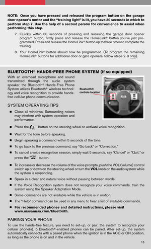
HOMELINK � UNIVERSAL TRANSCEIVER (if so equipped)
SYSTEM OPERATING TIPS
� Garage doors, electrical gates, entry doors, etc. will be activated during programming.
To avoid injury, make sure that people and objects are clear of all doors or gates during
programming. Yourvehicle’s engineshouldbeturned offwhile programming the
HomeLink �Transceiver.
� To program your HomeLink �Transceiver to operate a garage door, gate, or entry door
opener, home or office lighting, you need to be at the same location as the device.
NOTE: Garage dooropeners (manufactured after1996) have“rolling codepro-
tection”. Toprogram agarage dooropener equipped with“rolling codeprotec-
tion”, you will need to use a ladder to get up to the garage door opener motor to
be able to access the “smart or learn” program button.
PROGRAMMING YOUR HOMELINK � UNIVERSAL TRANSCEIVER (Mirror,
Sun Visor or Overhead Console)
1. To begin, press and hold the two
outer HomeLink �buttons (to
clear the memory) until the indi-
cator light blinks slowly (after 20
seconds) . Releasebothbut-
tons.
2. Position theend ofthe hand-
held transmitter 1-3inches
(26-76 mm)away fromthe
HomeLink �surface
3. Using bothhands, simultaneously pressandhold both theHomeLink �button you
want toprogram andthehand-held transmitter button. DONOT release the
buttons until step 4 has been completed.
4. Hold down both buttons until the indicator light on the HomeLink �flashes, changing
from a“slow blink” to a“rapidly flashing blink”.Thiscould takeupto90 seconds.
When the indicator light flashes rapidly, both buttons may be released. The rapidly
flashing light indicates successful programming. To activate the garage door or other
programmed device, press and hold the programmed HomeLink �button - releasing
when the device begins to activate.
5. If the indicator light on the HomeLink �blinks rapidly for two seconds and then turns
solid, HomeLink �has picked up a “rolling code” garage door opener signal. You will
need toproceed withthenext steps totrain theHomeLink �to complete the
programming which may require a ladder and another person for convenience.
6. Press and release the “smart” or “learn” program button located on the garage door
opener’s motor to activate the “training mode”. This button is usually located near the
antenna wire that hangs down from the motor. If the wire originates from under a light
lens, you will need to remove the lens to access the program button.
14