Page 97 of 241

GENERAL DESCRIPTION
MULTIPORT FUEL SYSTEM (MFI)13A-3
System Block Diagram
AK604116
Mass airflow sensor
Intake air temperature sensor
Intake camshaft position
sensor
Exhaust camshaft position
sensor
Crankshaft position sensor Throttle position sensor (main)
Throttle position sensor (sub)
Accelerator pedal position
sensor (sub) Accelerator pedal position
sensor (main) Engine coolant temperature
sensor Manifold absolute pressure
sensor
Heated oxygen sensor (front)
Heated oxygen sensor (rear)
Power steering pressure
switch Engine oil pressure switch Generator L terminal
Ignition switch-ST
Power supply Ignition switch-IG
CAN communication
(input signal)
· A/C switch
· Vehicle speed
· Fuel level sensor
· Transmission range switch
Fuel tank differential pressure
sensor Heated oxygen sensor
(3rd)*
Knock sensor
Generator FR terminal
Fuel tank temperature sensor
Vehicle speed sensor Engine control unit Barometric pressure sensor
[1] Fuel injection control
[2] Ignition timing control
[3] Throttle valve opening angle
control and idle speed control
[4]
MIVEC (Mitsubishi Innovative
Valve timing Electronic Control
system)
[5] Power supply control
(Power supply to sensor,
actuator)
[6] Fuel pump relay control
[7] Starter relay control
[8] Heated oxygen sensor heater
control
[9] A/C compressor relay control
[10] Generator control
[11] Evaporative emission purge
control
[12] EGR control
[13] Diagnosis output
[14] RAM data transmission
CAN communication
(output signal) Intake engine oil control
valve
A/C compressor relay No. 2 injector
No. 3 injector
No. 4 injector
Heated oxygen sensor (front)
heater
Heated oxygen sensor (rear)
heater Throttle actuator control
motor
Throttle actuator control
motor relay No. 1 injector
No. 1 ignition coil
No. 2 ignition coi
No. 3 ignition coi
No. 4 ignition coi
Fuel pump relay
Generator G terminal Heated oxygen sensor (3rd)
heater*
Multiport fuel injection (MFI)
relay Exhaust engine oil control
valve
Evaporative emission ventilation
solenoid Evaporative emission purge
solenoid
EGR valve (stepper motor)*
Starter relay
AB
Sensor, switch Engine control module (ECM) Actuator
NOTE
*1: California
Page 98 of 241

GENERAL DESCRIPTION
MULTIPORT FUEL SYSTEM (MFI)13A-4
Control System Diagram
AK604117
Fuel level
sensorFuel tank Air
inlet
2 Exhaust engine
oil control valve
1 Intake engine
oil control valve4 Manifold absolute pressure sensor
2 Intake air
temperature sensor
1 Mass airflow sensor
6 Intake
camshaft
position
sensor
7 Exhaust
camshaft
position
sensor
3 Throttle position
sensor (main/sub)
5 Evaporative emission
purge solenoid
3 Throttle actuator
control motor
12 Fuel tank differential
pressure sensor
13 Fuel tank
temperature
sensor10 Heated oxygen sensor (front)
11 Heated oxygen
sensor (rear)
8 Crankshaft position sensor5 Engine coolant
temperature sensor
9 Knock sensor
4 Injector
Fuel pump Fuel pressure
regulator Evaporative
emission
canister
6 Evaporative
emission
ventilation
solenoid
1 Mass airflow sensor
2 Intake air temperature sensor
3 Throttle position sensor (main/sub)
4 Manifold absolute pressure sensor
5 Engine coolant temperature sensor
6 Intake camshaft position sensor
7 Exhaust camshaft position sensor
8 Crankshaft position sensor
9 Knock sensor
10 Heated oxygen sensor (front)
11 Heated oxygen sensor (rear)
12 Fuel tank differential pressure sensor
13 Fuel tank temperature sensor
Ignition switch-IG
Ignition switch-ST
Power supply
CAN communication (input signal)1 Intake engine oil control valve
2 Exhaust engine oil control valve
3 Throttle actuator control motor
4 Injector
5 Evaporative emission purge solenoid
6 Evaporative emission ventilation
solenoid
Ignition coil, ignition power transistor
Multiport fuel injection (MFI) relay
Fuel pump relay
Starter relay
Throttle actuator control motor relay
Generator G terminal
Heated oxygen sensor heater
A/C compressor relay
Diagnostic output
CAN communication (output signal) SenseAct
Engine oil pressure switch
Power steering pressure switch
Generator FR terminal
Generator L terminal
Vehicle speed sensor Accelerator pedal position sensor (main/sub)
Decide
ECM
(with barometric
pressure sensor)
AB
Page 99 of 241

GENERAL DESCRIPTION
MULTIPORT FUEL SYSTEM (MFI)13A-5
AK604118
Fuel tank
Fuel level
sensor Air
inlet
2 Exhaust engine
oil control valve
1 Intake engine
oil control valve4 Manifold absolute pressure sensor
2 Intake air
temperature sensor
1 Mass airflow sensor
6 Intake
camshaft
position
sensor
7 Exhaust
camshaft
position
sensor
3 Throttle position
sensor (main/sub)
5 Evaporative emission
purge solenoid
3 Throttle actuator
control motor
12 Fuel tank differential
pressure sensor
13 Fuel tank
temperature
sensor11 Heated oxygen sensor (rear)
10 Heated
oxygen
sensor
(front)
12 Heated oxygen sensor (3rd)
8 Crankshaft position sensor5 Engine
coolant
temperature
sensor
9 Knock sensor
4 Injector
Fuel pump Fuel pressure
regulator Evaporative
emission
canister
6 Evaporative
emission
ventilation
solenoid
7 EGR valve
(stepper motor)
1 Mass airflow sensor
2 Intake air temperature sensor
3 Throttle position sensor (main/sub)
4 Manifold absolute pressure sensor
5 Engine coolant temperature sensor
6 Intake camshaft position sensor
7 Exhaust camshaft position sensor
8 Crankshaft position sensor
9 Knock sensor
10 Heated oxygen sensor (front)
11 Heated oxygen sensor (rear)
12 Heated oxygen sensor (3rd)
13 Fuel tank differential pressure sensor
14 Fuel tank temperature sensor
Ignition switch-IG
Ignition switch-ST
Power supply
CAN communication (input signal)1 Intake engine oil control valve
2 Exhaust engine oil control valve
3 Throttle actuator control motor
4 Injector
5 Evaporative emission purge solenoid
6 Evaporative emission ventilation
solenoid
7 EGR valve (stepper motor)
Ignition coil, ignition power transistor
Multiport fuel injection (MFI) relay
Fuel pump relay
Starter relay
Throttle actuator control motor relay
Generator G terminal
Heated oxygen sensor heater
A/C compressor relay
Diagnostic output
CAN communication (output signal) SenseAct
Engine oil pressure switch
Power steering pressure switch
Generator FR terminal
Generator L terminal
Vehicle speed sensor Accelerator pedal position sensor (main/sub)
Decide
ECM
(with barometric
pressure sensor)
AB
Page 100 of 241

CONTROL UNIT
MULTIPORT FUEL SYSTEM (MFI)13A-6
CONTROL UNITM2132021500153
ENGINE CONTROL MODULE (ECM)
ECM is installed in the engine room. ECM judges
(calculates) the optimum control to deal with the con
-
stant minute changes in driving conditions based on
information input from the sensors and drives the
actuator. ECM is composed of 32-bit microprocessor
and Random Access Memory (RAM), Read Only
Memory (ROM) and Input /Output interface. ECM uses flash-memory ROM that allows re-writing of
data so that change and correction of control data is
possible using special tools. It also uses Electrically
Erasable Programmable Read Only Memory
(EEPROM) so that studied compensation data is not
deleted even if battery terminals are disconnected.
ECM CONNECTOR INPUT/OUTPUT PIN ARRANGEMENT
NOTE: *: California
AK604119
ECM
Microprocessor
RAM Input
interfaceOutput
interface Input
sensorOutput
actuator
AB
ROM
AK602565AC
1 2 3 4 5 6 7 8 9 10 11 1213 14 15 16
17 18 19 20 21 91
90
89
87
86
84 85
83 82
88 92 93 94
95 96 97 98 99
109
108
107 106
105
104
103
102
112 113 114 115 116 117 118
100 101
111
110
41
40
39
38
37
36
35
34
33 32
31
30
29
28
27
26
25
24
23
2260
59
58
57
56
55
54
53
52
51
50
49 48
47
46
45
44
43
4263
61 62 6471 72 73 74 75 76 77 78 79 80 81
1Intake engine oil control valve2No.1 injector
3No.2 injector4Ignition coil No.1 (ignition power transistor)
5Ignition coil No.2 (ignition power transistor)6Starter active signal
7Exhaust camshaft position sensor8Crankshaft position sensor
9Sensor supplied voltage10Throttle position sensor (main)
11Throttle position sensor (sub)12Power supply voltage applied to throttle
position sensor
13Throttle position sensor ground14Intake camshaft position sensor
Page 101 of 241

SENSOR
MULTIPORT FUEL SYSTEM (MFI)13A-8
SENSORM2132001000565.
MASS AIRFLOW SENSOR
Mass airflow sensor is installed in the air intake hose. Mass air-
flow sensor is composed of an extremely small heatsensing
resistor. The mass airflow sensor controls the amount of elec
-
tric current flowing into the heat sensing resistor to keep the
heat sensing resistor at a constant temperature to the intake air
temperature. The faster the air flow speed, the higher the mass
flow rate.Because the amount of heat transfer from the heat
sensing resistor to the air increases, the mass airflow sensor
increases the amount of electric current to the heat sensing
resistor. Thus, the amount of electric current increases in
accordance with the air mass flow rate. The mass airflow sen
-
sor measures the air mass flow rate by detecting the amount of
electric current. The mass airflow sensor amplifies the detected
electric current amount and outputs it into the ECM. ECM uses
this output current and engine speed to calculate and decide
basic fuel injection time. Sensor properties are as shown in the
figure.
.
INTAKE AIR TEMPERATURE SENSOR
Intake air temperature sensor is built in to the mass airflow sen-
sor. Intake air temperature sensor detects intake air tempera-
ture through thermistor's resistance change and outputs the
voltage according to intake air temperature to ECM. ECM uses
this output voltage to compensate fuel injection control and
ignition timing control. Sensor properties are as shown in the
figure.
AK602252AC
Sensing areaSilicon substrate
Heat sensing
resistor
Intake air
Diaphragm
AK602221AG
From MFI relay
Mass airflow sensorECMOutput current mA
Mass flow g/s
AK602253AC
Sensory part
(thermistor)
Page 102 of 241
SENSOR
MULTIPORT FUEL SYSTEM (MFI)13A-9
.
MANIFOLD ABSOLUTE PRESSURE SENSOR
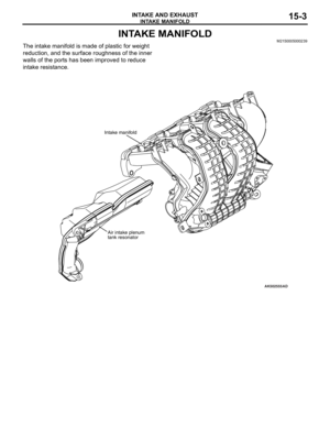
The manifold absolute pressure sensor is installed in the intake
manifold. Manifold absolute pressure sensor uses a piezo
resistive semiconductor to output the voltage according to man
-
ifold absolute pressure to ECM. ECM uses this output voltage
to compensate fuel injection volume according to manifold
absolute pressure. Sensor properties are as shown in the fig
-
ure.
.
AK602207
Intake air
temperature C ( F)
AG
Resistance kΩOutput voltage V
Intake air temperature
sensor (thermistor)5V
Intake air
temperature C ( F) ECM
AK602254 ACPressure Manifold absolute
pressure sensor
AK602206AH
5V
0
101 5V
GroundOutput voltage V
Pressure kPa (in.Hg) Manifold absolute
pressure sensorPower supply
Output signal
ECM
Page 103 of 241

SENSOR
MULTIPORT FUEL SYSTEM (MFI)13A-10
ENGINE COOLANT TEMPERATURE SENSOR
The engine coolant temperature sensor is installed in the ther-
mostat housing. Engine coolant temperature sensor uses ther-
mistor's resistance change to detect coolant temperature and
output the voltage according to coolant temperature to ECM.
ECM uses this output voltage to appropriately control fuel injec
-
tion volume, idle speed and ignition timing. Sensor properties
are as shown in the figure.
.
THROTTLE POSITION SENSOR
The throttle position sensor is installed in the throttle body.
Throttle position sensor outputs voltage to ECM based on the
throttle shaft rotation angle. ECM uses this signal to detect the
throttle valve opening angle to perform throttle actuator control
motor feedback control. This throttle position sensor uses Hall
IC and is a non-contact type.
.
AK602255AC
Sensory part
(thermistor)
AK602208
Engine coolant
temperature C ( F)
AG
Output voltage V
5V Engine coolant
temperature sensor
(thermistor)
Engine coolant
temperature C ( F) ECM
Resistance kΩ
AK604120AB
Throttle body
Throttle
position
sensor
Page 104 of 241

SENSOR
MULTIPORT FUEL SYSTEM (MFI)13A-11
STRUCTURE AND SYSTEM
Throttle position sensor is composed of a permanent magnet
fixed on the throttle shaft, Hall IC that outputs voltage according
to magnetic flux density and a stator that efficiently introduces
magnetic flux from the permanent magnet to Hall IC.
Magnetic flux density at Hall IC is proportional to the output
voltage.
Throttle position sensor has 2 output systems − throttle position
sensor (main) and throttle position sensor (sub), and the output
voltage is output to ECM. When throttle valve turns, output volt
-
age of throttle position sensor (main) and throttle position sen-
sor (sub) changes. This allows ECM to detect actual throttle
opening angle. ECM uses this output voltage for throttle actua
-
tor control motor feedback control. Also, ECM compares output
voltage of the throttle position sensor (main) and throttle posi
-
tion sensor (sub) to check for abnormality in the throttle position
sensor. The relationship between throttle opening angle and
output voltage of the throttle position sensor (main) and throttle
position sensor (sub) is as shown in the figure below.
AK602566AC
Hall ICStator
Yo k e
Fixed to the motor cover Magnet Throttle shaft
To ECM
AK604555Magnet flux Fully opened Fully closedHall IC
Half opened
Hall ICAB