2008 MERCEDES-BENZ E-CLASS SALOON lock
[x] Cancel search: lockPage 316 of 401

Changing the bulbs
313
Front bulbs Bulb Type
1 Additional turn
signal lamp
LEDs
35 2 Turn signal lamp PY 21 W
3 Dipped-beam
headlamp
H7 55 W
36
or
D1S 35 W* 37 4 Main-beam
headlamp H7 55 W
Side lamp/park-
ing lamp W 5 W
or
LED*
35 5 Front foglamp
H11 55 W
35 Rear bulbs
Bulb Type
6 Third brake
lamp
LED
35 7 Rear foglamp
HiP
35 Side lamp/park-
ing lamp
HiP
35 Reversing lamp
HiP
35 Brake lamp
HiP
35
or
LED* 35 Turn signal lamp
HiP
35 8 Licence plate
lamp C 5 W Before changing bulbs
You can replace the following bulbs:
R
Dipped-beam headlamps (vehicles with
halogen headlamps)
R Main-beam headlamp
R Replacing the bulb in the side lamp/park-
ing lamp (vehicles with halogen headlamps)
R Turn signal lamp (front)
R Licence plate lamp
Observe the following points:
R Use only the bulb types specified here.
R To prevent a short-circuit, switch off the
lights before changing a bulb.
R Only hold bulbs with a clean, lint-free cloth.
R Do not work with wet or greasy fingers.
R If the new bulb still does not light up, con-
sult a qualified specialist workshop, e.g. a
Mercedes-Benz Service Centre.
i Have the headlamp setting checked reg-
ularly at a qualified specialist workshop,
e.g. a Mercedes-Benz Service Centre.
35 These bulbs must be replaced at a qualified specialist workshop, e.g. a Mercedes-Benz Service Centre.
36 Vehicles with halogen headlamps.
37 Vehicles with xenon headlamps*: always have these bulbs changed at a qualified specialist workshop, e.g. a Mercedes-Benz Service Centre. Practical advice
* optional
211_AKB; 2; 5, en-GB
mkalafa,
Version: 2.9.4
2008-02-29T16:57:07+01:00 - Seite 313 ZDateiname: 6515_3416_02_buchblock.pdf; preflight
Page 317 of 401

Changing the bulbs
314 Changing the front bulbs
Halogen or bi-xenon* headlamps
1
Bulb holder for turn signal
2 Bulb holder for main-beam headlamp
3 Bulb holder for side/parking lamp
4 Housing cover for dipped-beam headlamp
(halogen/bi-xenon headlamps)
Replacing dipped-beam headlamps
(vehicles with halogen headlamps) X
Switch off the lights.
X Open the bonnet.
X Turn housing cover 4anti-clockwise and
remove it.
X Turn the bulb holder anti-clockwise until it
is released. X
Pull out the bulb holder.
X Change the bulb.
X Insert the bulb holder into the headlamp
and turn it clockwise until it engages.
X Place housing cover 4back on and turn it
clockwise until it engages.
Replacing the bulbs in the main-beam
headlamp X
Switch off the lights.
X Open the bonnet.
X Turn bulb holder 2anti-clockwise and
remove it together with the bulb.
X Pull the bulb out of bulb holder 2.
X Insert the new bulb into bulb holder 2.
X Insert bulb holder 2into the headlamp
and turn it clockwise until it engages.
Replacing the bulb in the side lamp/
parking lamp (vehicles with halogen
headlamps) X
Switch off the lights.
X Open the bonnet. X
Turn bulb holder 3anti-clockwise and pull
it out.
X Pull the bulb out of bulb holder 3.
X Insert the new bulb into bulb holder 3.
X Insert bulb holder 3into the headlamp
and turn it clockwise until it engages.
Replacing the bulbs in the turn signal
lamps X
Switch off the lights.
X Open the bonnet.
X Turn bulb holder 1anti-clockwise and
remove it along with the bulb.
X Turn the bulb anti-clockwise, applying
slight pressure, and remove it from bulb
holder 1.
X Insert the new bulb into bulb holder 1and
turn it clockwise.
X Insert bulb holder 1into the headlamp
and turn it clockwise until it engages. Practical advice
* optional
211_AKB; 2; 5, en-GB
mkalafa,
Version: 2.9.4 2008-02-29T16:57:07+01:00 - Seite 314Dateiname: 6515_3416_02_buchblock.pdf; preflight
Page 318 of 401

Replacing the wiper blades
315Changing the rear bulbs
Changing the bulbs in the licence plate
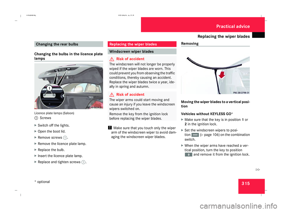
lamps Licence plate lamps (Saloon)
1
Screws
X Switch off the lights.
X Open the boot lid.
X Remove screws 1.
X Remove the licence plate lamp.
X Replace the bulb.
X Insert the licence plate lamp.
X Replace and tighten screws 1. Replacing the wiper blades
Windscreen wiper blades
G
Risk of accident
The windscreen will not longer be properly
wiped if the wiper blades are worn. This
could prevent you from observing the traffic
conditions, thereby causing an accident.
Replace the wiper blades twice a year, ide-
ally in spring and autumn. G
Risk of accident
The wiper arms could start moving and
cause an injury if you leave the windscreen
wipers switched on.
Remove the key from the ignition lock
before replacing the wiper blades.
! Make sure that you touch only the wiper
arm of the windscreen wiper to avoid dam-
aging the windscreen wiper blades. Removing Moving the wiper blades to a vertical posi-
tion
Vehicles without KEYLESS GO*
X
Make sure that the key is in position 1or
2 in the ignition lock.
X Set the windscreen wipers to posi-
tion u (Ypage 106) on the combination
switch.
X When the wiper arms have reached a ver-
tical position, turn the key to position
M and remove it from the ignition lock. Practical advice
* optional
211_AKB; 2; 5, en-GB
mkalafa ,V ersion: 2.9.4
2008-02-29T16:57:07+01:00 - Seite 315 ZDateiname: 6515_3416_02_buchblock.pdf; preflight
Page 319 of 401

Replacing the wiper blades
316
X
Fold the wiper arm away from the wind-
screen until it engages.
X Set the wiper blade at right angles to the
wiper arm.
Vehicles with KEYLESS GO*
X Switch off the engine.
X Take your foot off the brake pedal.
X Set the windscreen wipers to posi-
tion u (Ypage 106) on the combination
switch.
X Press the KEYLESS GO button repeatedly
until the windscreen wipers start.
X When the wiper arms have reached a ver-
tical position, press the KEYLESS GO but-
ton.
X Fold the wiper arm away from the wind-
screen until it engages.
X Set the wiper blade at right angles to the
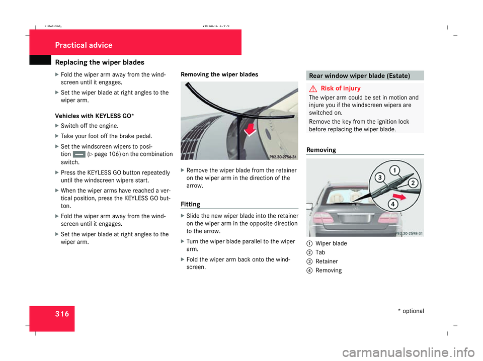
wiper arm. Removing the wiper blades X
Remove the wiper blade from the retainer
on the wiper arm in the direction of the
arrow.
Fitting X
Slide the new wiper blade into the retainer
on the wiper arm in the opposite direction
to the arrow.
X Turn the wiper blade parallel to the wiper
arm.
X Fold the wiper arm back onto the wind-
screen. Rear window wiper blade (Estate)
G
Risk of injury
The wiper arm could be set in motion and
injure you if the windscreen wipers are
switched on.
Remove the key from the ignition lock
before replacing the wiper blade.
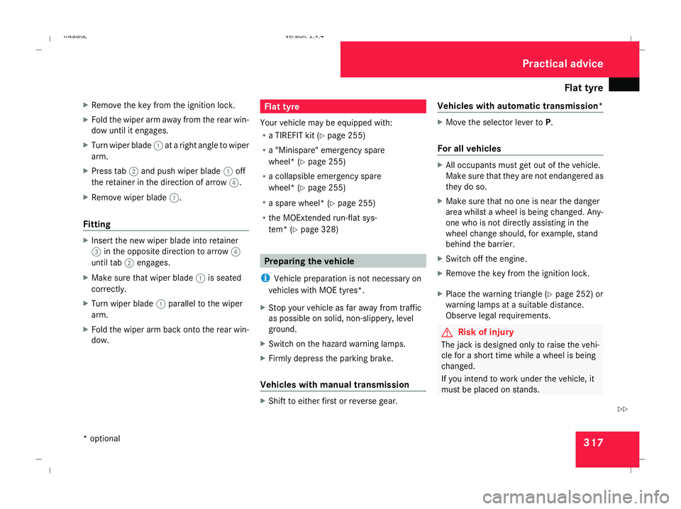
Removing 1
Wiper blade
2 Tab
3 Retainer
4 Removing Practical advice
* optional
211_AKB; 2; 5, en-GB
mkalafa
, Version: 2.9.4 2008-02-29T16:57:07+01:00 - Seite 316Dateiname: 6515_3416_02_buchblock.pdf; preflight
Page 320 of 401

Flat tyre
317
X
Remove the key from the ignition lock.
X Fold the wiper arm away from the rear win-
dow until it engages.
X Turn wiper blade 1at a right angle to wiper
arm.
X Press tab 2and push wiper blade 1off
the retainer in the direction of arrow 4.
X Remove wiper blade 1.
Fitting X
Insert the new wiper blade into retainer
3 in the opposite direction to arrow 4
until tab 2engages.
X Make sure that wiper blade 1is seated
correctly.
X Turn wiper blade 1parallel to the wiper
arm.
X Fold the wiper arm back onto the rear win-
dow. Flat tyre
Your vehicle may be equipped with:
R a TIREFIT kit (Y page 255)
R a "Minispare" emergency spare
wheel* (Y page 255)
R a collapsible emergency spare
wheel* (Y page 255)
R a spare wheel* (Y page 255)
R the MOExtended run-flat sys-
tem* (Y page 328) Preparing the vehicle
i Vehicle preparation is not necessary on
vehicles with MOE tyres*.
X Stop your vehicle as far away from traffic
as possible on solid, non-slippery, level
ground.
X Switch on the hazard warning lamps.
X Firmly depress the parking brake.
Vehicles with manual transmission X
Shift to either first or reverse gear. Vehicles with automatic transmission* X
Move the selector lever to P.
For all vehicles X
All occupants must get out of the vehicle.
Make sure that they are not endangered as
they do so.
X Make sure that no one is near the danger
area whilst a wheel is being changed. Any-
one who is not directly assisting in the
wheel change should, for example, stand
behind the barrier.
X Switch off the engine.
X Remove the key from the ignition lock.
X Place the warning triangle ( Ypage 252) or
warning lamps at a suitable distance.
Observe legal requirements. G
Risk of injury
The jack is designed only to raise the vehi-
cle for a short time while a wheel is being
changed.
If you intend to work under the vehicle, it
must be placed on stands. Practical advice
* optional
211_AKB; 2; 5, en-GB
mkalafa,
Version: 2.9.4
2008-02-29T16:57:07+01:00 - Seite 317 ZDateiname: 6515_3416_02_buchblock.pdf; preflight
Page 321 of 401

Flat tyre
318 Make sure that the jack is placed on a firm,
non-slip, level surface. Do not use wooden
blocks or similar as jacking supports. Oth-
erwise, the jack will not be able to achieve
its load-bearing capacity due to the restric-
ted height.
Do not start the engine at any time while
the wheel is being changed.
Do not lie under the vehicle when it is being
supported by the jack. If you do not raise
the vehicle as described, it could slip off the
jack (e.g. if the engine is started or a door
or the boot lid/tailgate is opened or closed)
and you could sustain serious injuries. Using the TIREFIT kit
You can use the TIREFIT kit to seal small
punctures, particularly those in the tyre tread.
You can use TIREFIT in outdoor temperatures
down to -20 °C. G
Risk of accident
In the following situations, your safety is at
particular risk and TIREFIT is unable to pro-
vide breakdown assistance: R
if there are cuts or punctures in the tyre
greater than 4 mm
R if the wheel rim is damaged
R if you have driven at very low tyre pres-
sures or on a flat tyre
Do not drive any further. Consult a qualified
specialist workshop which has the neces-
sary specialist knowledge and tools to carry
out the work required.
Mercedes-Benz recommends that you use
a Mercedes-Benz Service Centre for this
purpose. In particular, work relevant to
safety or on safety-related systems must be
carried out at a qualified specialist work-
shop.
X Do not remove any foreign objects which
have penetrated the tyre, e.g. screws or
nails.
X Remove TIREFIT, the accompanying "max.
80 km/h "sticker and the electric air pump
from the stowage well underneath the
boot/luggage compartment floor
(Y page 254). 1
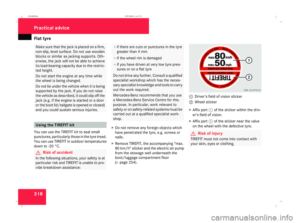
Driver's field of vision sticker
2 Wheel sticker
X Affix part 1of the sticker within the driv-
er's field of vision.
X Affix part 2of the sticker near the valve
on the wheel with the defective tyre. G
Risk of injury
TIREFIT must not come into contact with
your skin, eyes or clothing. Practical advice
211_AKB; 2; 5, en-GB
mkalafa
, Version: 2.9.4 2008-02-29T16:57:07+01:00 - Seite 318Dateiname: 6515_3416_02_buchblock.pdf; preflight
Page 322 of 401

Flat tyre
319R
If TIREFIT comes into contact with your
eyes or skin, immediately rinse thor-
oughly with clean water.
R Change out of clothing which has come
into contact with TIREFIT immediately.
R If an allergic reaction occurs, consult a
doctor immediately.
Keep TIREFIT away from children.
R If TIREFIT is swallowed, immediately
rinse your mouth out thoroughly with
water and drink plenty of water.
R Do not induce vomiting. Consult a doctor
immediately.
R Do not inhale TIREFIT fumes.
i If TIREFIT leaks out, allow it to dry. It can
then be removed like a layer of film.
If you get TIREFIT on your clothing, have it
cleaned as soon as possible with perchloro-
ethylene. G
Risk of injury
Comply with the manufacturer's safety
instructions shown on the sticker on the
electric air pump. i
Your vehicle may be equipped with one of
two different air pumps. Version 1 can be
identified by the flap, behind which the
hose with the pressure gauge and cable are
located; version 2 has a pressure gauge
integrated in the electric air pump.
Version 1 Version 1
1
TIREFIT sealant filler bottle
2 Flap
3 Recess
4 On/off switch
5 Electric connector with cable
6 Air pump hose
7 Flange X
Open flap 2on the electric air pump.
X Pull connector 5and air pump hose 6
from the housing.
X Screw air pump hose 6onto flange 7of
TIREFIT sealant filler bottle 1.
X Place TIREFIT sealant filler bottle 1head
downwards into recess 3of the electric
air pump. 8
Filler hose
9 Valve
X Remove the cap from valve 9on the faulty
tyre. Practical advice
211_AKB; 2; 5, en-GB
mkalafa,
Version: 2.9.4 2008-02-29T16:57:07+01:00 - Seite 319 ZDateiname: 6515_3416_02_buchblock.pdf; preflight
Page 323 of 401

Flat tyre
320a
Pressure release screw
b Pressure gauge
X Make sure pressure release screw aon
pressure gauge bis fully closed.
X Screw filler hose 8onto valve 9.
X Insert plug 5into the socket of the ciga-
rette lighter* (Y page 209) or into a 12V
power socket in your vehicle
(Y page 210).
X Turn the key to position 1(Y page 76) in
the ignition lock. X
Press on/off switch 4on the electric air
pump to I.
The electric air pump is switched on. The
tyre is inflated.
i First, TIREFIT is pumped into the tyre. The
pressure can briefly rise to around 5 bar.
Do not switch off the electric pump dur-
ing this phase.
X Let the electric pump run for five minutes.
The tyre should then have a pressure of at
least 1.8 bar.
! Do not operate the electric air pump for
longer than six minutes without a break.
Otherwise, it may overheat.
The air pump can be operated again once
it has cooled down.
If a pressure of 1.8 bar is not reached after
five minutes:
X Switch off and disconnect the electric air
pump and drive the vehicle forwards or
backwards approximately 10 m.
This distributes the TIREFIT more evenly.
X Remove TIREFIT filler bottle 1from the
electric pump.
X Pump up the tyre again. G
Risk of accident
If a pressure of 1.8 bar is not achieved after
five minutes, the tyre is too badly damaged.
Do not drive any further. Consult a qualified
specialist workshop which has the neces-
sary specialist knowledge and tools to carry
out the work required. Mercedes-Benz rec-
ommends that you use a Mercedes-Benz
Service Centre for this purpose. In particu-
lar, work relevant to safety or on safety-
related systems must be carried out at a
qualified specialist workshop.
If a tyre pressure of 1.8 bar is reached:
X Press on/off switch 4on the electric air
pump to 0.
The electric air pump is switched off.
X Disconnect the electric air pump and stow
it away.
X Fold up the warning triangle and stow it
away.
X Pull away immediately.
This distributes the TIREFIT more evenly
around the tyre.
X Stop after driving for approximately ten
minutes and check the tyre pressure with
the electric air pump. Practical advice
* optional
211_AKB; 2; 5, en-GB
mkalafa,
Version: 2.9.4 2008-02-29T16:57:07+01:00 - Seite 320Dateiname: 6515_3416_02_buchblock.pdf; preflight