2008 MERCEDES-BENZ E-CLASS SALOON tow
[x] Cancel search: towPage 329 of 401

Flat tyre
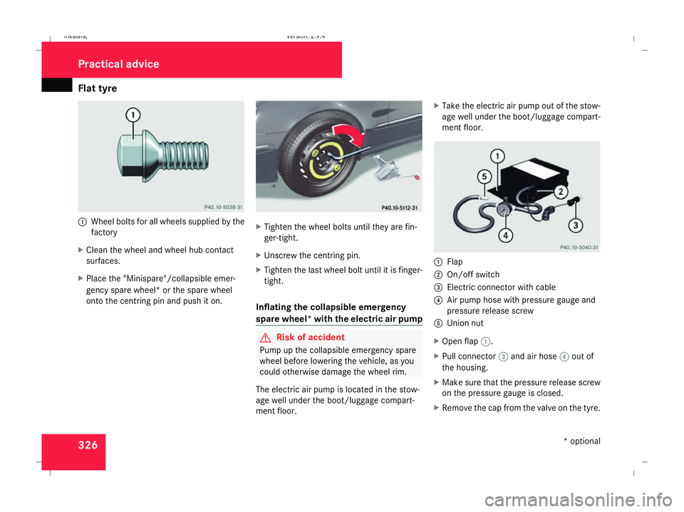
3261
Wheel bolts for all wheels supplied by the
factory
X Clean the wheel and wheel hub contact
surfaces.
X Place the "Minispare"/collapsible emer-
gency spare wheel* or the spare wheel
onto the centring pin and push it on. X
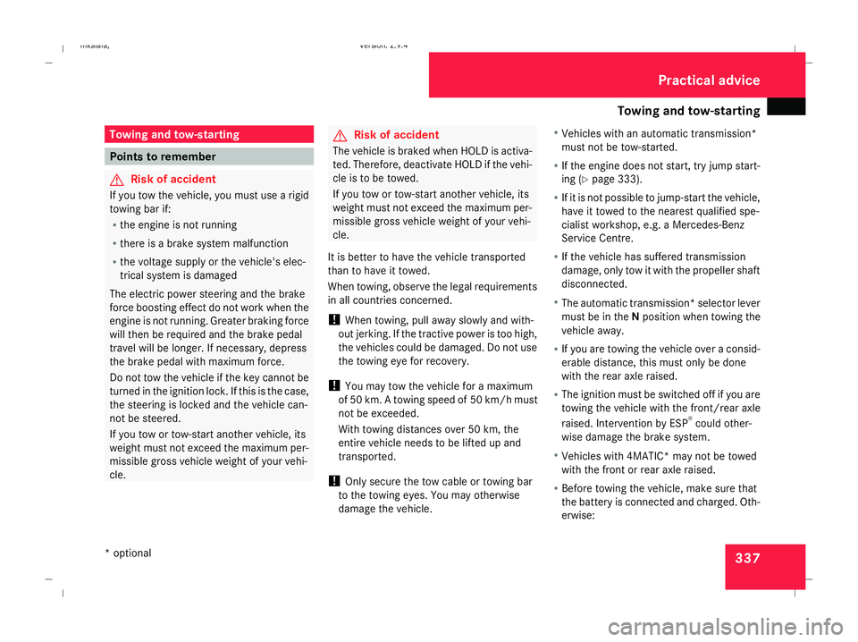
Tighten the wheel bolts until they are fin-
ger-tight.
X Unscrew the centring pin.
X Tighten the last wheel bolt until it is finger-
tight.
Inflating the collapsible emergency
spare wheel* with the electric air pump G
Risk of accident
Pump up the collapsible emergency spare
wheel before lowering the vehicle, as you
could otherwise damage the wheel rim.
The electric air pump is located in the stow-
age well under the boot/luggage compart-
ment floor. X
Take the electric air pump out of the stow-
age well under the boot/luggage compart-
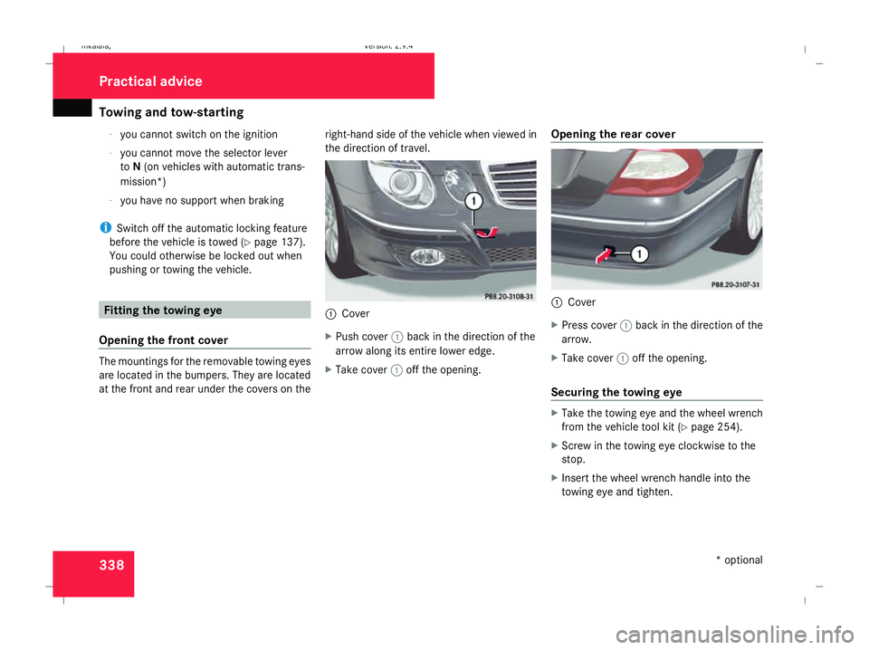
ment floor. 1
Flap
2 On/off switch
3 Electric connector with cable
4 Air pump hose with pressure gauge and
pressure release screw
5 Union nut
X Open flap 1.
X Pull connector 3and air hose 4out of
the housing.
X Make sure that the pressure release screw
on the pressure gauge is closed.
X Remove the cap from the valve on the tyre. Practical advice
* optional
211_AKB; 2; 5, en-GB
mkalafa,
Version: 2.9.4 2008-02-29T16:57:07+01:00 - Seite 326Dateiname: 6515_3416_02_buchblock.pdf; preflight
Page 330 of 401

Flat tyre
327
X
Screw union nut 5on air hose 4onto the
valve.
X Insert plug 3into the cigarette lighter
socket* ( Ypage 209) or into a 12V socket
in your vehicle (Y page 210).
X Make sure that the key is in position 2in
the ignition lock.
X Press on/off switch 2on the electric air
pump to I.
The electric air pump is switched on. The
tyre is inflated.
X When a tyre pressure of 3.5 bar has been
reached, press 0on the electric air pump
switch.
The electric air pump is switched off.
! Do not operate the electric air pump for
longer than six minutes without a break.
Otherwise, it may overheat.
The air pump can be operated again once
it has cooled down.
If the tyre pressure is higher than 3.5 bar: X
Open the pressure release screw on the
pressure gauge until the tyre pressure is
correct.
X Disconnect the electric air pump and stow
it away.
Lowering the vehicle X
Lower the vehicle. To do this, turn the crank
of the jack anti-clockwise until the vehicle
is standing firmly on the ground again.
X Place the jack to one side. 1
–5 Wheel bolts
X Tighten the wheel bolts evenly in a cross-
wise pattern in the sequence indica-
ted ( 1to5). The tightening torque must
be 130 Nm . G
Risk of accident
Have the tightening torque checked imme-
diately after a wheel is changed. The wheels
could work loose if they are not tightened
to a torque of 130 Nm.
X Turn the jack back to its initial position and
store it and the rest of the vehicle tool kit
in the boot/luggage compartment.
Vehicles with the "Minispare"/collapsible
emergency spare wheel*:
X Pack the faulty wheel in the protective film
provided with the "Minispare"/collapsible
emergency spare wheel* and transport the
wheel in the boot/luggage compartment.
or
X Depending on the size of the wheel, you
may also be able to secure the faulty wheel
in the spare wheel well. In this case, you
will have to remove the stowage well casing
from the spare wheel well and stow it
securely in the boot/luggage compart-
ment.
i Do not activate the tyre pressure moni-
tor* until the deflated tyre has been
removed from the vehicle. Practical advice
* optional
211_AKB; 2; 5, en-GB
mkalafa,
Version: 2.9.4 2008-02-29T16:57:07+01:00 - Seite 327 ZDateiname: 6515_3416_02_buchblock.pdf; preflight
Page 340 of 401

Towing and tow-starting
337Towing and tow-starting
Points to remember
G
Risk of accident
If you tow the vehicle, you must use a rigid
towing bar if:
R the engine is not running
R there is a brake system malfunction
R the voltage supply or the vehicle's elec-
trical system is damaged
The electric power steering and the brake
force boosting effect do not work when the
engine is not running. Greater braking force
will then be required and the brake pedal
travel will be longer. If necessary, depress
the brake pedal with maximum force.
Do not tow the vehicle if the key cannot be
turned in the ignition lock. If this is the case,
the steering is locked and the vehicle can-
not be steered.
If you tow or tow-start another vehicle, its
weight must not exceed the maximum per-
missible gross vehicle weight of your vehi-
cle. G
Risk of accident
The vehicle is braked when HOLD is activa-
ted. Therefore, deactivate HOLD if the vehi-
cle is to be towed.
If you tow or tow-start another vehicle, its
weight must not exceed the maximum per-
missible gross vehicle weight of your vehi-
cle.
It is better to have the vehicle transported
than to have it towed.
When towing, observe the legal requirements
in all countries concerned.
! When towing, pull away slowly and with-
out jerking. If the tractive power is too high,
the vehicles could be damaged. Do not use
the towing eye for recovery.
! You may tow the vehicle for a maximum
of 50 km. A towing speed of 50 km/h must
not be exceeded.
With towing distances over 50 km, the
entire vehicle needs to be lifted up and
transported.
! Only secure the tow cable or towing bar
to the towing eyes. You may otherwise
damage the vehicle. R
Vehicles with an automatic transmission*
must not be tow-started.
R If the engine does not start, try jump start-
ing (Y page 333).
R If it is not possible to jump-start the vehicle,
have it towed to the nearest qualified spe-
cialist workshop, e.g. a Mercedes-Benz
Service Centre.
R If the vehicle has suffered transmission
damage, only tow it with the propeller shaft
disconnected.
R The automatic transmission* selector lever
must be in the Nposition when towing the
vehicle away.
R If you are towing the vehicle over a consid-
erable distance, this must only be done
with the rear axle raised.
R The ignition must be switched off if you are
towing the vehicle with the front/rear axle
raised. Intervention by ESP ®
could other-
wise damage the brake system.
R Vehicles with 4MATIC* may not be towed
with the front or rear axle raised.
R Before towing the vehicle, make sure that
the battery is connected and charged. Oth-
erwise: Practical advice
* optional
211_AKB; 2; 5, en-GB
mkalafa
,V ersion: 2.9.4
2008-02-29T16:57:07+01:00 - Seite 337 ZDateiname: 6515_3416_02_buchblock.pdf; preflight
Page 341 of 401

Towing and tow-starting
338-
you cannot switch on the ignition
- you cannot move the selector lever
to N(on vehicles with automatic trans-
mission*)
- you have no support when braking
i Switch off the automatic locking feature
before the vehicle is towed (Y page 137).
You could otherwise be locked out when
pushing or towing the vehicle. Fitting the towing eye
Opening the front cover The mountings for the removable towing eyes
are located in the bumpers. They are located
at the front and rear under the covers on the right-hand side of the vehicle when viewed in
the direction of travel. 1
Cover
X Push cover 1back in the direction of the
arrow along its entire lower edge.
X Take cover 1off the opening. Opening the rear cover 1
Cover
X Press cover 1back in the direction of the
arrow.
X Take cover 1off the opening.
Securing the towing eye X
Take the towing eye and the wheel wrench
from the vehicle tool kit ( Ypage 254).
X Screw in the towing eye clockwise to the
stop.
X Insert the wheel wrench handle into the
towing eye and tighten. Practical advice
* optional
211_AKB; 2; 5, en-GB
mkalafa
,V ersion: 2.9.4
2008-02-29T16:57:07+01:00 - Seite 338 Dateiname: 6515_3416_02_buchblock.pdf; preflight
Page 342 of 401

Towing and tow-starting
339Towing the vehicle
! You may tow the vehicle for a maximum
of 50 km. A towing speed of 50 km/h must
not be exceeded.
With towing distances over 50 km, the
entire vehicle needs to be lifted up and
transported.
! Vehicles with 4MATIC* may not be towed
with the front or rear axle raised.
! The engine must be switched off (key in
ignition lock in position 0or position 1) if
the vehicle is being towed with the rear axle
raised or if the parking brake is being tested
on a dynamometer. Intervention by ESP ®
could otherwise damage the brake system.
Vehicles with manual transmission X
Turn the key to position 2in the ignition
lock.
X Shift to neutral. Vehicles with automatic transmission* X
Turn the key to position 2in the ignition
lock.
X Move the selector lever to N. Tow-starting (emergency engine
starting)
Please note:
R Vehicles with an automatic transmission*
must not be tow-started.
R The battery must be connected.
R The engine and catalytic converter must be
cold.
R Avoid repeated and lengthy starting
attempts.
Vehicles with manual transmission X
Turn the key to position 2in the ignition
lock.
X Fully depress the clutch pedal.
X Shift to neutral. X
Tow the vehicle or let it roll.
X Shift to a suitable gear and bring the clutch
pedal up slowly. Do not depress the accel-
erator pedal.
The engine is started. Removing the towing eye
X Take the wheel wrench from the vehicle
tool kit ( Ypage 254).
X Insert the wheel wrench handle into the
towing eye and turn it anti-clockwise.
X Unscrew the towing eye.
X Replace the cover and press it until it
engages.
X Return the towing eye and the wheel
wrench to the vehicle tool kit. Practical advice
* optional
211_AKB; 2; 5, en-GB
mkalafa
,V ersion: 2.9.4
2008-02-29T16:57:07+01:00 - Seite 339 ZDateiname: 6515_3416_02_buchblock.pdf; preflight
Page 343 of 401

Fuses
340 Transporting the vehicle
The towing eyes can be used to pull the vehi-
cle onto a trailer or transporter for transport-
ing purposes.
! Only lash the vehicle down by the wheels
or wheel rims, not by parts of the vehicle
such as axle or steering components. The
vehicle could otherwise be damaged.
Vehicles with manual transmission X
Shift to neutral.
Vehicles with automatic transmission* X
Turn the key to position 2in the ignition
lock.
X Move the selector lever to N. Fuses
Notes on changing fuses
The fuses in your vehicle serve to close down
faulty circuits. If a fuse blows, all the compo-
nents on the circuit and their functions will
fail.
Blown fuses must be replaced with fuses of
the same rating, which you can recognise by
the colour and value. The fuse ratings are lis-
ted in the fuse allocation chart. A Mercedes-
Benz Service Centre will be happy to advise
you. G
Risk of fire
Only use fuses that have been approved for
Mercedes-Benz vehicles and which have
the correct fuse rating for the systems con-
cerned. Do not attempt to repair or bridge
faulty fuses. Otherwise, a circuit overload
could cause a fire. Have the cause traced
and rectified at a qualified specialist work-
shop, e.g. a Mercedes-Benz Service Centre.
If the newly inserted fuse also blows, have the
cause traced and rectified at a qualified spe-
cialist workshop, e.g. a Mercedes-Benz
Service Centre. !
Only use fuses that have been approved
for Mercedes-Benz vehicles and which
have the correct fuse rating for the system
concerned. Otherwise, components or sys-
tems could be damaged.
The fuses are located in various fuse boxes:
R Main fuse box on the driver's side of the
dashboard
R Fuse box in the boot/luggage compart-
ment on the left-hand side of the vehicle
Fuse allocation chart The fuse allocation chart is in the main fuse
box in the dashboard.
Before changing a fuse
X Park the vehicle.
X Switch off all electrical consumers.
X Remove the key from the ignition lock. Practical advice
* optional
211_AKB; 2; 5, en-GB
mkalafa,
Version: 2.9.4 2008-02-29T16:57:07+01:00 - Seite 340Dateiname: 6515_3416_02_buchblock.pdf; preflight
Page 349 of 401

Vehicle identification plates
346phones/wireless devices in the vehicle.
This also ensures that interference
between these devices and the vehicle's
electronics is kept to a minimum. If instal-
led, the exterior aerial conducts the elec-
tromagnetic fields transmitted by a mobile
phone to the exterior of the vehicle. Frequency range Maximum trans-
mission output
(watts)
Short wave
(< 50 MHz) 100
4 m waveband 20
2 m waveband 50
70 cm waveband 35
25 cm waveband 10
!
If electrical or electronic equipment
which does not comply with the above
installation conditions is operated inside
the vehicle, the vehicle's operating permit
may be invalidated (EU Directive
95/54/EC) - Automotive EMC directive) Vehicle identification plates
Vehicle identification plate with vehi-
cle identification number (VIN) and
paint code number
The vehicle identification plate is located at
the bottom of the door frame on the front-
passenger side. 1
Vehicle identification plate
X Open the driver's door.
You will see vehicle identification plate
1. Vehicle identification plate (example)
1
Vehicle identification plate
2 Vehicle manufacturer
3 EU type approval number
4 Vehicle identification number (VIN)
5 Maximum permissible gross vehicle
weight
6 Maximum permissible towing weight
7 Maximum permissible front axle load
8 Maximum permissible rear axle load
9 Paint code number Technical data
211_AKB; 2; 5, en-GB
mkalafa,
Version: 2.9.4
2008-02-29T16:57:07+01:00 - Seite 346 Dateiname: 6515_3416_02_buchblock.pdf; preflight
Page 373 of 401

Vehicle weights
370 E 200
KOMPRESSOR E 230 E 280 E 280 4MATIC
Maximum per-
missible front
axle load Saloon 1,005 kg 1,045 kg 1,045 kg 1,150 kg
Estate 975 kg 1,005 kg 1,005 kg 1,110 kg
Maximum per-
missible rear
axle load Saloon 1,145 kg 1,175 kg 1,185 kg 1,200 kg
Estate 1,320 kg 1,345 kg 1,355 kg 1,370 kg
Towing a trailer Saloon 1,195 kg 1,225 kg 1,235 kg 1,250 kg
Estate 1,395 kg 1,420 kg 1,430 kg 1,430 kg
Maximum roof
load 100 kg 100 kg 100 kg 100 kg
Maximum boot
load
57 100 kg 100 kg 100 kg 100 kg
E 350 E 350 4MATIC E 500 E 500 4MATIC
Unladen weight
(in accordance
with EC direc-
tive) Saloon 1,690 kg 1,785 kg 1,785 kg 1,880 kg
Estate 1,810 kg 1,910 kg 1,895 kg 1,990 kg
57
On vehicles with AIRMATIC and on the Estate it is important to observe the maximum permissible rear axle load. Technical data
211_AKB; 2; 5, en-GB
mkalafa,
Version: 2.9.4 2008-02-29T16:57:07+01:00 - Seite 370Dateiname: 6515_3416_02_buchblock.pdf; preflight