2008 MERCEDES-BENZ E-CLASS SALOON tow
[x] Cancel search: towPage 207 of 401
Loading and stowing
204
i
The belt reel can be used to secure light
loads against the side wall of the boot/lug-
gage compartment to prevent them from
moving around.
X Insert two mounting elements 2into a
loading rail.
X Turn mounting elements 2in the loading
rail to N.
X Insert belt reel 3into mounting ele-
ments 2.
X Turn mounting element 2to‹ until
you feel it clearly engage in the loading rail.
X Press locking button 1on the belt reel and
pull the safety net out in the direction of the
arrow.
X Place the load between the securing net
and the boot/luggage compartment side
wall.
X Press locking button 3on the belt reel
with one hand.
X With your other hand, slowly extend the net
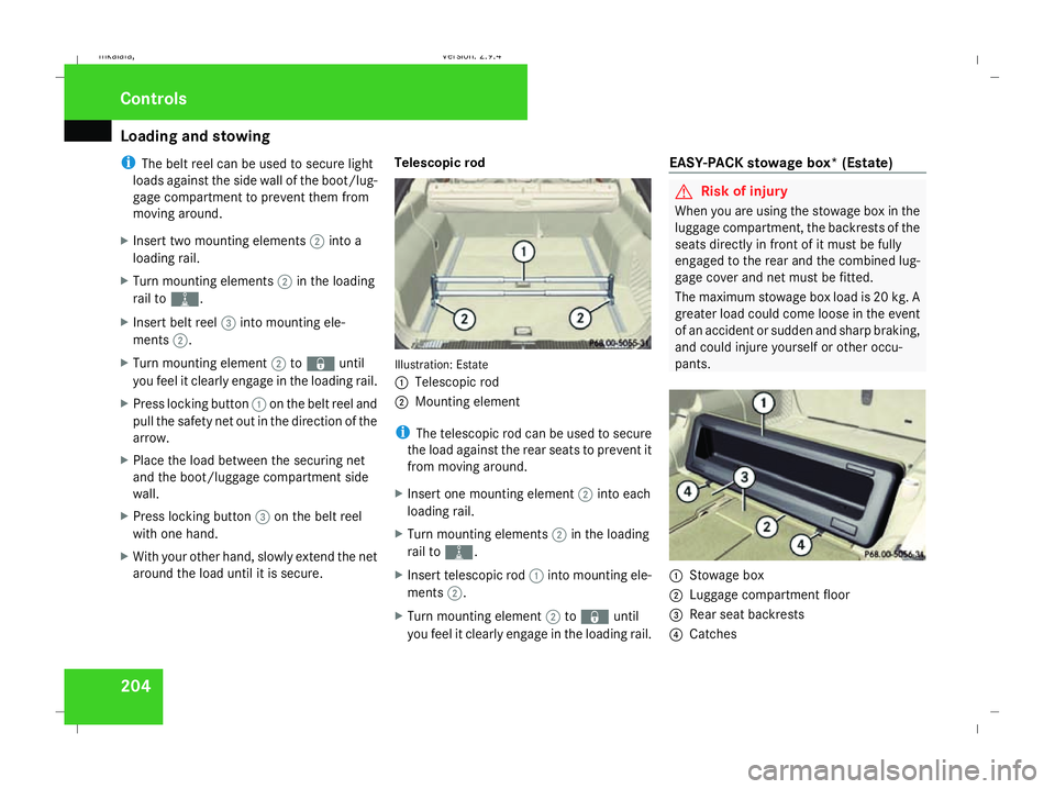
around the load until it is secure. Telescopic rod Illustration: Estate
1
Telescopic rod
2 Mounting element
i The telescopic rod can be used to secure
the load against the rear seats to prevent it
from moving around.
X Insert one mounting element 2into each
loading rail.
X Turn mounting elements 2in the loading
rail to N.
X Insert telescopic rod 1into mounting ele-
ments 2.
X Turn mounting element 2to‹ until
you feel it clearly engage in the loading rail. EASY-PACK stowage box* (Estate) G
Risk of injury
When you are using the stowage box in the
luggage compartment, the backrests of the
seats directly in front of it must be fully
engaged to the rear and the combined lug-
gage cover and net must be fitted.
The maximum stowage box load is 20 kg. A
greater load could come loose in the event
of an accident or sudden and sharp braking,
and could injure yourself or other occu-
pants. 1
Stowage box
2 Luggage compartment floor
3 Rear seat backrests
4 Catches Controls
211_AKB; 2; 5, en-GB
mkalafa,
Version: 2.9.4 2008-02-29T16:57:07+01:00 - Seite 204Dateiname: 6515_3416_02_buchblock.pdf; preflight
Page 208 of 401
Loading and stowing
205
Installing the stowage box
X
Fold the two backrests 3forward
(Y page 198).
X Guide stowage box 1into the luggage
compartment through one of the rear doors
with the opening facing towards the front
of the vehicle.
X Press catches 4on stowage box 1into
the gap between backrest 3and the lug-
gage compartment floor.
X Fold backrest 3back (Y page 200).
i Stowage box 1is also held in place from
above by the combined luggage cover and
net.
Loading the stowage box
X Fold backrest 3forward (Y page 198).
X Load stowage box 1through the opening
on the front.
i Stowage box 1in the luggage compart-
ment is closed off by the rear bench seat
and can carry a maximum load of 20 kg.
X Fold backrest 3back (Y page 200). Removing the stowage box
X
Fold double backrest 3forward
(Y page 198).
X Slide stowage box 1with catches 4for-
wards to remove it from the mountings.
X Remove stowage box 1sideways through
a rear door.
X Fold backrest 3back (Y page 200). Stowage compartments
G
Risk of injury
The stowage compartments must be closed
when items are stored in them. Luggage
nets are not designed to secure heavy
items of luggage.
You or other vehicle occupants could be
injured by objects being thrown around if
you:
R brake sharply
R change direction suddenly
R have an accident
Sharp-edged and fragile objects must not
be carried in the luggage net. Do not carry hard objects in the ruffled
pockets. Objects must not protrude over
the top of the ruffled pockets.
i You will find an overview of the stowage
compartments on (Y page 36).
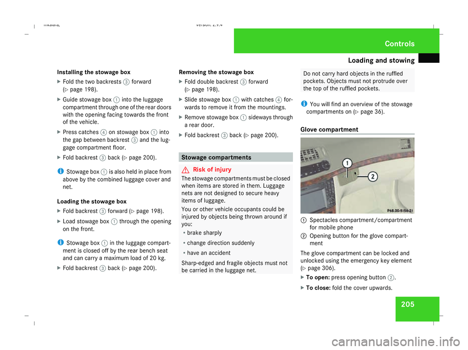
Glove compartment 1
Spectacles compartment/compartment
for mobile phone
2 Opening button for the glove compart-
ment
The glove compartment can be locked and
unlocked using the emergency key element
(Y page 306).
X To open: press opening button 2.
X To close: fold the cover upwards. Controls
211_AKB; 2; 5, en-GB
mkalafa,
Version: 2.9.4 2008-02-29T16:57:07+01:00 - Seite 205 ZDateiname: 6515_3416_02_buchblock.pdf; preflight
Page 209 of 401
Loading and stowing
206
Spectacles compartment/compartment
for mobile phone
X To open: press lightly on compart-
ment 1.
X To close: slide compartment 1back in
until it clicks into place.
Stowage compartment in the centre
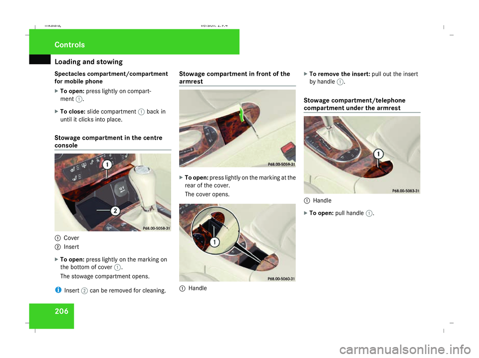
console 1
Cover
2 Insert
X To open: press lightly on the marking on
the bottom of cover 1.
The stowage compartment opens.
i Insert 2can be removed for cleaning. Stowage compartment in front of the
armrest
X
To open: press lightly on the marking at the
rear of the cover.
The cover opens. 1
Handle X
To remove the insert: pull out the insert
by handle 1.
Stowage compartment/telephone
compartment under the armrest 1
Handle
X To open: pull handle 1. Controls
211_AKB; 2; 5, en-GB
mkalafa,
Version: 2.9.4 2008-02-29T16:57:07+01:00 - Seite 206Dateiname: 6515_3416_02_buchblock.pdf; preflight
Page 210 of 401
Features
207
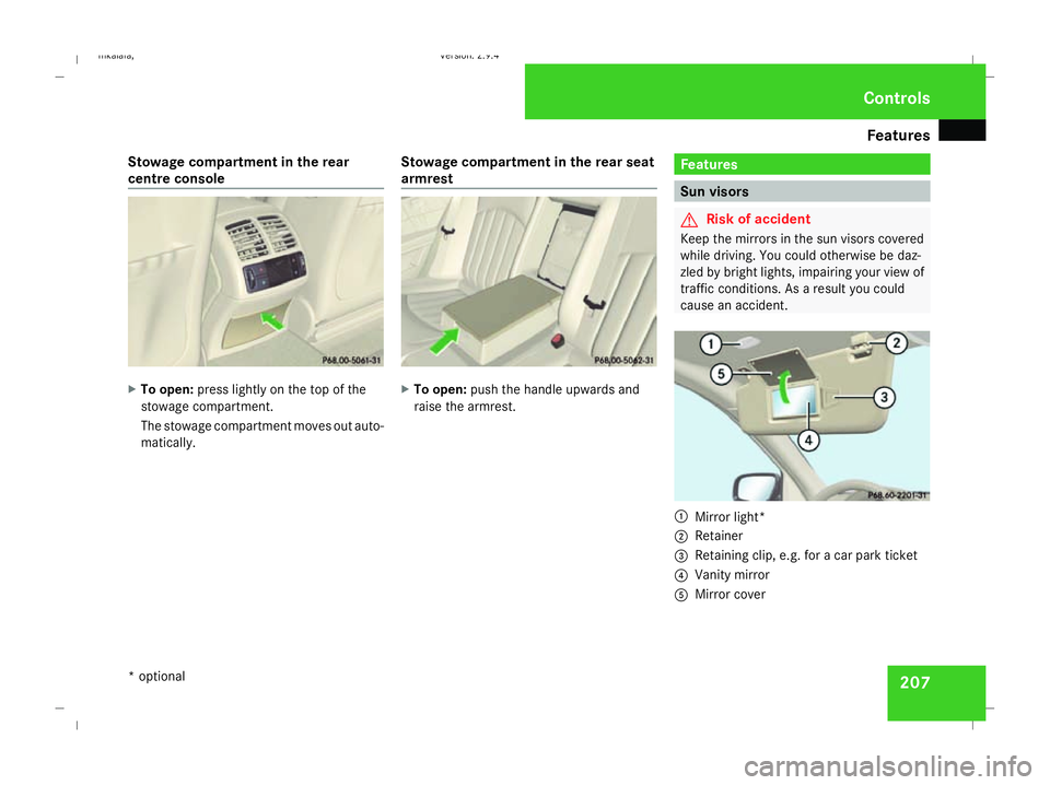
Stowage compartment in the rear
centre console
X
To open: press lightly on the top of the
stowage compartment.
The stowage compartment moves out auto-
matically. Stowage compartment in the rear seat
armrest X
To open: push the handle upwards and
raise the armrest. Features
Sun visors
G
Risk of accident
Keep the mirrors in the sun visors covered
while driving. You could otherwise be daz-
zled by bright lights, impairing your view of
traffic conditions. As a result you could
cause an accident. 1
Mirror light*
2 Retainer
3 Retaining clip, e.g. for a car park ticket
4 Vanity mirror
5 Mirror cover Cont
rols
* optional
211_AKB; 2; 5, en-GB
mkalafa
,V ersion: 2.9.4
2008-02-29T16:57:07+01:00 - Seite 207 ZDateiname: 6515_3416_02_buchblock.pdf; preflight
Page 213 of 401
Features
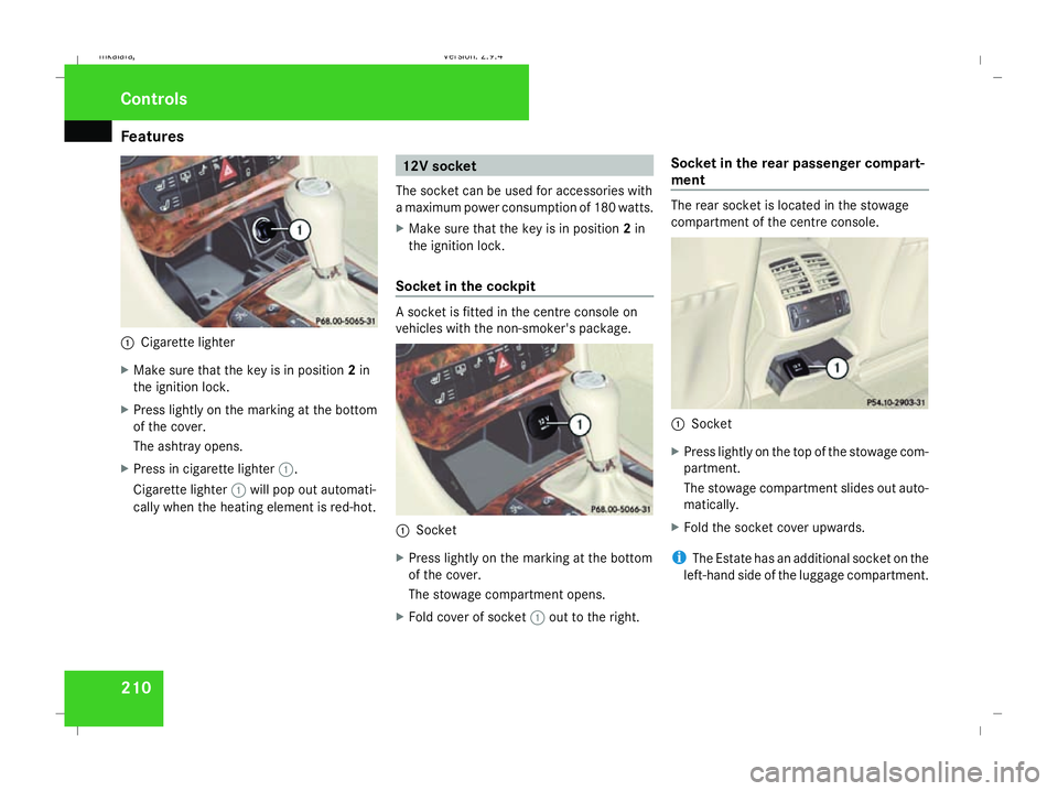
2101
Cigarette lighter
X Make sure that the key is in position 2in
the ignition lock.
X Press lightly on the marking at the bottom
of the cover.
The ashtray opens.
X Press in cigarette lighter 1.
Cigarette lighter 1will pop out automati-
cally when the heating element is red-hot. 12V socket
The socket can be used for accessories with
a maximum power consumption of 180 watts.
X Make sure that the key is in position 2in
the ignition lock.
Socket in the cockpit A socket is fitted in the centre console on
vehicles with the non-smoker's package.
1
Socket
X Press lightly on the marking at the bottom
of the cover.
The stowage compartment opens.
X Fold cover of socket 1out to the right. Socket in the rear passenger compart-
ment The rear socket is located in the stowage
compartment of the centre console.
1
Socket
X Press lightly on the top of the stowage com-
partment.
The stowage compartment slides out auto-
matically.
X Fold the socket cover upwards.
i The Estate has an additional socket on the
left-hand side of the luggage compartment. Controls
211_AKB; 2; 5, en-GB
mkalafa,
Version: 2.9.4 2008-02-29T16:57:07+01:00 - Seite 210Dateiname: 6515_3416_02_buchblock.pdf; preflight
Page 218 of 401

Features
215
X
Erase the memory of the integrated remote
control (Y page 216) before programming
it for the first time.
X Turn the key to position 2in the ignition
lock.
X Press and hold one of transmitter buttons
2 to4 on the integrated remote control.
Indicator lamp 1starts to flash after a
short while. It flashes about once a second.
i Indicator lamp 1flashes immediately
the first time the transmitter button is pro-
grammed. If this transmitter button has
already been programmed, indicator
lamp 1will only start flashing at a rate of
once a second after 20 seconds have
elapsed.
X Keep the transmitter buttons depressed.
X Point the garage door's remote control with
the transmitter towards the left-hand side
of the rear-view mirror from a distance of 5
to 20 cm.
i The distance between the garage door's
remote control and the integrated garage
door opener depends on the system of the
garage door drive. You might require sev-
eral attempts. You should test every posi- tion for at least 20 seconds before trying
another position.
X Keep the transmitter button on the garage
door's remote control depressed until indi-
cator lamp 1starts to flash rapidly.
The programming was successful if indica-
tor lamp 1flashes rapidly.
X Release the transmitter buttons on the
garage door's remote control and the inte-
grated remote control.
If indicator lamp 1goes out after approxi-
mately 20 seconds and did not flash rapidly
before this:
X Release the transmitter buttons on the
integrated and portable remote controls.
X Repeat the programming procedure. At the
same time change the distance between
the garage door's remote control and the
transmitter buttons in the rear-view mirror.
i If the garage door system works with a
rolling code, after programming you must
synchronise the remote control integrated
in the rear-view mirror with the garage door
system receiver.
You will find further information in the
garage door opening system's operating instructions, e.g. the sections on “Synchro-
nising the transmitter” or “Registering a
new transmitter”. You can also call the hot-
line mentioned above.
Opening or closing the garage door Once programmed, the integrated remote
control will assume the function of the garage
door system's remote control. Please read
the operating instructions for the garage door
system.
X
Turn the key to position 2in the ignition
lock.
X Press the transmitter button on the rear-
view mirror that you have programmed to
operate the garage door.
Garage door system with fixed code: indi-
cator lamp 1lights up continuously.
Garage door system with rolling code: indi-
cator lamp 1flashes briefly and then lights
up for approximately two seconds. This is
repeated for up to 20 seconds.
i The transmitter will transmit a signal for
as long as the transmitter button is being
pressed. The transmission will be halted
after a maximum of 20 seconds and indi- Cont
rols
211_AKB; 2; 5, en-GB
mkalafa
,V ersion: 2.9.4
2008-02-29T16:57:07+01:00 - Seite 215 ZDateiname: 6515_3416_02_buchblock.pdf; preflight
Page 220 of 401
217
Running-in notes
............................... 218
Refuelling ........................................... 218
Engine compartment ........................222
Tyres and wheels .............................. 227
Winter driving ................................... 234
Driving tips ........................................ 236
Driving abroad ................................... 238
Trailer towing .................................... 239
Service ............................................... 243
Care .................................................... 244 Operation
211_AKB; 2; 5, en-GB
mkalafa,
Version: 2.9.4 2008-02-29T16:57:07+01:00 - Seite 217Dateiname: 6515_3416_02_buchblock.pdf; preflight
Page 234 of 401
Tyres and wheels
231pressure, e.g. if the tyre is penetrated by a
foreign object.
In the event of a sudden loss of pressure,
bring the vehicle to a halt by braking care-
fully. Do not make any sudden steering
movements when doing so.
While the vehicle is in motion, the tyre pres-
sure loss warning system monitors the set
tyre pressure using the rotational speed of
the wheels. This enables the system to detect
significant pressure loss in a tyre. If the speed
of rotation of a wheel changes as a result of
a loss of pressure, a corresponding warning
message will appear in the multi-function dis-
play.
The function of the tyre pressure loss warning
system is limited or delayed if:
R snow chains are fitted to your vehicle's
tyres
R road conditions are wintry
R you are driving on sand or gravel
R you adopt a very sporty driving style (cor-
nering at high speeds or driving with high
rates of acceleration)
R you are towing a very heavy or large trailer
R you are driving with a heavy load (in the
vehicle or on the roof) Restarting the tyre pressure loss warn-
ing system Restart the tyre pressure loss warning system
if you have:
R
changed the tyre pressure
R changed the wheels or tyres
R fitted new wheels or tyres
X Before restarting, consult the table of tyre
pressures on the inside of the fuel filler flap
to ensure that the tyre pressure in all four
tyres is set correctly for the operating con-
ditions concerned.
X Also observe the notes in the section on
tyre pressures (Y page 229). G
Risk of accident
The tyre pressure loss warning system can
only give reliable warnings if you have set
the correct tyre pressure.
If an incorrect tyre pressure is set, these
incorrect values will be monitored.
A tyre with insufficient pressure results in
an instability of the vehicle when driving,
thus increasing the risk of an accident. X
Make sure that the key is in position 2in
the ignition lock.
The standard display appears in the multi-
function display (Y page 125).
X Press korj to select the tyre pres-
sure function:
Run Flat Indicator active
Menu: R-Button æ
X Press the reset button on the left of the
instrument cluster.
The following message appears in the
multi-function display:
Restart Run Flat Indicator?
Yes Cancel
If you wish to confirm the restart:
X Press the æbutton.
The following message appears in the
multi-function display:
Run Flat Indicator restarted
After a teach-in period, the tyre pressure
loss warning system will monitor the set
tyre pressures of all four tyres.
If you wish to cancel the restart:
X Press the çbutton.
or
X Wait until the message Operation
211_AKB; 2; 5, en-GB
mkalafa
,V ersion: 2.9.4
2008-02-29T16:57:07+01:00 - Seite 231 ZDateiname: 6515_3416_02_buchblock.pdf; preflight