2008 MERCEDES-BENZ E-CLASS SALOON clock setting
[x] Cancel search: clock settingPage 30 of 401
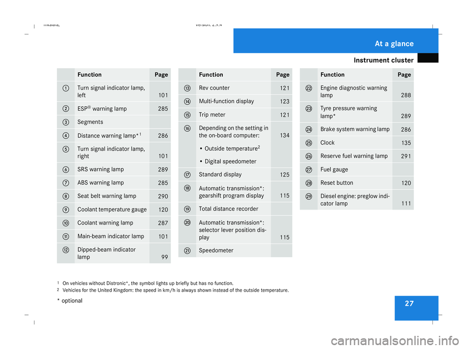
Instrument cluster
27Function Page
1 Turn signal indicator lamp,
left
101
2
ESP
®
warning lamp 285
3 Segments
4
Distance warning lamp*
1 286
5 Turn signal indicator lamp,
right
101
6 SRS warning lamp
289
7 ABS warning lamp
285
8 Seat belt warning lamp
290
9 Coolant temperature gauge
120
a Coolant warning lamp
287
b Main-beam indicator lamp
101
c Dipped-beam indicator
lamp
99 Function Page
d Rev counter
121
e Multi-function display
123
f Trip meter
121
g Depending on the setting in
the on-board computer:
134
• Outside temperature
2 • Digital speedometer
h Standard display
125
j
Automatic transmission*:
gearshift program display
115
k Total distance recorder
l
Automatic transmission*:
selector lever position dis-
play
115
m Speedometer Function Page
n Engine diagnostic warning
lamp
288
o Tyre pressure warning
lamp*
289
p Brake system warning lamp
286
q Clock
135
r Reserve fuel warning lamp
291
s Fuel gauge
t Reset button
120
u Diesel engine: preglow indi-
cator lamp
111
1
On vehicles without Distronic*, the symbol lights up briefly but has no function.
2 Vehicles for the United Kingdom: the speed in km/h is always shown instead of the outside temperature. At a glance
* optional
211_AKB; 2; 5, en-GB
mkalafa,
Version: 2.9.4 2008-02-29T16:57:07+01:00 - Seite 27Dateiname: 6515_3416_02_buchblock.pdf; preflight
Page 32 of 401
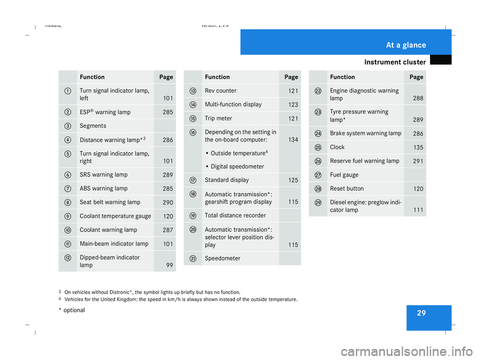
Instrument cluster
29Function Page
1 Turn signal indicator lamp,
left
101
2
ESP
®
warning lamp 285
3 Segments
4
Distance warning lamp*
3 286
5 Turn signal indicator lamp,
right
101
6 SRS warning lamp
289
7 ABS warning lamp
285
8 Seat belt warning lamp
290
9 Coolant temperature gauge
120
a Coolant warning lamp
287
b Main-beam indicator lamp
101
c Dipped-beam indicator
lamp
99 Function Page
d Rev counter
121
e Multi-function display
123
f Trip meter
121
g Depending on the setting in
the on-board computer:
134
• Outside temperature
4 • Digital speedometer
h Standard display
125
j
Automatic transmission*:
gearshift program display
115
k Total distance recorder
l
Automatic transmission*:
selector lever position dis-
play
115
m Speedometer Function Page
n Engine diagnostic warning
lamp
288
o Tyre pressure warning
lamp*
289
p Brake system warning lamp
286
q Clock
135
r Reserve fuel warning lamp
291
s Fuel gauge
t Reset button
120
u Diesel engine: preglow indi-
cator lamp
111
3
On vehicles without Distronic*, the symbol lights up briefly but has no function.
4 Vehicles for the United Kingdom: the speed in km/h is always shown instead of the outside temperature. At a glance
* optional
211_AKB; 2; 5, en-GB
mkalafa,
Version: 2.9.4 2008-02-29T16:57:07+01:00 - Seite 29Dateiname: 6515_3416_02_buchblock.pdf; preflight
Page 138 of 401

On-board computer
135
X
Press the èor· button to select the
Settings... menu.
X Press the jbutton to call up the selec-
tion of submenus.
X Press the æorç button to select the
Time/Date submenu.
Setting the time
X Use the jbutton to select Clock,
hours Press R to confirm (orClock,
minutes Press R to confirm ).
X Press the æorç button to set a
value.
X Press the reset button on the left of the
instrument cluster.
The set time is stored.
Setting the date
X Press the jbutton to select Set date
Day (orSet date Month orSet date
Year).
X Press the æorç button to set the
values.
X Press the j,èorÿ button to
select a different display. Setting constant headlamp mode If you have set constant headlamp mode and
the light switch is in position MorU,
the side lamps, dipped-beam headlamps and
licence plate lighting are switched on auto-
matically when the engine is running. Turning
the light switch to a different position
switches on the corresponding lights. Make
sure that the light switch is turned to Bor
U if you switch off constant headlamp
mode while driving in the dark.
In countries in which constant headlamp
mode is a legal requirement, Constantis the
factory setting.
X Press the èor· button to select the
Settings... menu.
X Press the jbutton to call up the selec-
tion of submenus.
X Press the æorç button to select the
Lighting submenu.
X Press the jbutton to select Headlamp
mode. X
Press the æorç button to set the
mode for the headlamps to ManualorCon-
stant (constant headlamp mode).
X Press the j,èorÿ button to
select a different display.
Switching the surround lighting on or
off If the surround lighting is switched on, the
following lights will be switched on automat-
ically in the dark after you have unlocked the
vehicle using the key:
R
the side lamps
R the tail lamps
R the licence plate lighting
R the front foglamps
The surround lighting switches off automati-
cally if you open the driver's door or after 40
seconds.
X Press èor· to select the Set-
tings... menu.
X Press the jbutton to call up the selec-
tion of submenus.
X Press the æorç button to select the
Lighting submenu. Controls
211_AKB; 2; 5, en-GB
mkalafa,
Version: 2.9.4
2008-02-29T16:57:07+01:00 - Seite 135 ZDateiname: 6515_3416_02_buchblock.pdf; preflight
Page 174 of 401
Air conditioning
171
4-zone Thermotronic*: the temperature for
each of the four air-conditioning zones can be
set individually. You can set the temperature
separately for the driver's and front-
passenger sides as well as for the left and
right sides of the rear compartment.
Setting the temperature in the front
compartment using 2-zone Thermatic X
Make sure that the key is in position 2in
the ignition lock.
X To increase/reduce: turn thumbwheels
1 and 7clockwise or anti-clockwise
(Y page 164). Only change the temperature
setting in small increments. Start at 22 †.
Setting the temperature in the front
compartment via 4-zone
Thermotronic* X
Make sure that the key is in position 2in
the ignition lock.
X To increase/reduce: press the$or
% button. Only change the temperature
setting in small increments. Start at 22 †.
The set temperature is shown in the 4-zone
Thermotronic* display. Setting the temperature in the rear
compartment via 4-zone
Thermotronic* X
Make sure that the key is in position 2in
the ignition lock.
X Press the ™button.
The 4-zone Thermotronic* display switches
to the rear-compartment air-conditioning
settings.
X To increase/reduce: press the$or
% button. Only change the temperature
setting in small increments. Start at 22 †.
The set temperature is shown in the 4-zone
Thermotronic* display. The 4-zone
Thermotronic* display changes back to the
standard display about five seconds after a
button is pressed.
i You can also return to the standard dis-
play by pressing the ™button again. Setting the rear-compartment temper-
ature via the rear-compartment air con-
ditioning* X
Make sure that the key is in position 2in
the ignition lock.
X To increase/reduce: press the$or
% button. Only change the temperature
setting in small increments. Start at 22 †. Adjusting the air vents
G
Risk of injury
Very hot or very cold air can flow from the
air vents. This could cause burns or frost-
bite to bare skin in the immediate vicinity
of the vents. Keep bare skin away from
these air outlets. If necessary, direct the
airflow away to a different area of the vehi-
cle interior.
Please observe the following notes to ensure
that the air can flow freely through the air
vents:
R Keep the air inlet between the windscreen
and the bonnet free of deposits, such as ice Cont
rols
* optional
211_AKB; 2; 5, en-GB
mkalafa ,V ersion: 2.9.4
2008-02-29T16:57:07+01:00 - Seite 171 ZDateiname: 6515_3416_02_buchblock.pdf; preflight
Page 177 of 401
Air conditioning
174
The symbols for the air distribution have the
following meanings: Symbol Meaning
Z
Directs the airflow through the
centre, the side and the demis-
ter air vents
a
Directs the airflow through the
centre and side air vents
X
Directs the airflow to the entire
vehicle interior
Y
Directs the airflow through the
centre, the side and the foot-
well vents in the front and rear
X
Make sure that the key is in position 2in
the ignition lock.
X Turn thumbwheel 1or7 to the corre-
sponding symbol (Y page 166). The thumb-
wheel can also be turned to the area
between two symbols. Setting the airflow
X Make sure that the key is in position 2in
the ignition lock.
X To increase/reduce: press theQor
· button. Demisting the windscreen
i You should only select the "demisting"
function until the windscreen is clear again.
X Make sure that the key is in position 2in
the ignition lock.
X To activate: press theybutton.
The indicator lamp in the ybutton
comes on.
The system automatically switches to the
following functions:
R cooling with air dehumidification on
R high airflow 29
R high temperature 29
R air distribution to the windscreen and
front side windows
R air-recirculation mode off X
To deactivate: press theybutton.
The indicator lamp in the ybutton goes
out. The previously selected settings come
into effect again. The cooling with air dehu-
midification function remains on. Air-recir-
culation mode remains deactivated.
or
X Press the Ubutton.
The indicator lamp in the ybutton goes
out. Airflow and air distribution are set to
automatic mode.
or
X 2-zone Thermatic: turn thumbwheels1
or 7 clockwise or anti-clockwise
(Y page 164).
or
X 2-zone Thermatic: press theQor
· button.
29 Depending on the outside temperature. Cont
rols
211_AKB; 2; 5, en-GB
mkalafa
,V ersion: 2.9.4
2008-02-29T16:57:07+01:00 - Seite 174 Dateiname: 6515_3416_02_buchblock.pdf; preflight
Page 259 of 401
Where will I find...?
256
Removing the "Minispare" emergency
spare wheel*/collapsible emergency
spare wheel or spare wheel*
X Saloon: remove the luggage well
(Y page 256).
X Estate: remove the luggage compartment
floor (Y page 194).
X Turn fastening element 3anti-clockwise.
X Remove the "Minispare" emergency spare
wheel/collapsible emergency spare wheel
or the spare wheel 2.
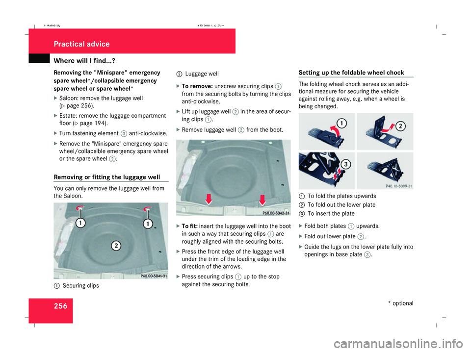
Removing or fitting the luggage well You can only remove the luggage well from
the Saloon. 1
Securing clips 2
Luggage well
X To remove: unscrew securing clips 1
from the securing bolts by turning the clips
anti-clockwise.
X Lift up luggage well 2in the area of secur-
ing clips 1.
X Remove luggage well 2from the boot. X
To fit: insert the luggage well into the boot
in such a way that securing clips 1are
roughly aligned with the securing bolts.
X Press the front edge of the luggage well
under the trim of the loading edge in the
direction of the arrows.
X Press securing clips 1up to the stop
against the securing bolts. Setting up the foldable wheel chock The folding wheel chock serves as an addi-
tional measure for securing the vehicle
against rolling away, e.g. when a wheel is
being changed.
1
To fold the plates upwards
2 To fold out the lower plate
3 To insert the plate
X Fold both plates 1upwards.
X Fold out lower plate 2.
X Guide the lugs on the lower plate fully into
openings in base plate 3.Practical advice
* optional
211_AKB; 2; 5, en-GB
mkalafa,
Version: 2.9.4 2008-02-29T16:57:07+01:00 - Seite 256Dateiname: 6515_3416_02_buchblock.pdf; preflight