2008 MERCEDES-BENZ E-CLASS SALOON display
[x] Cancel search: displayPage 183 of 401

Sliding sunroof
180
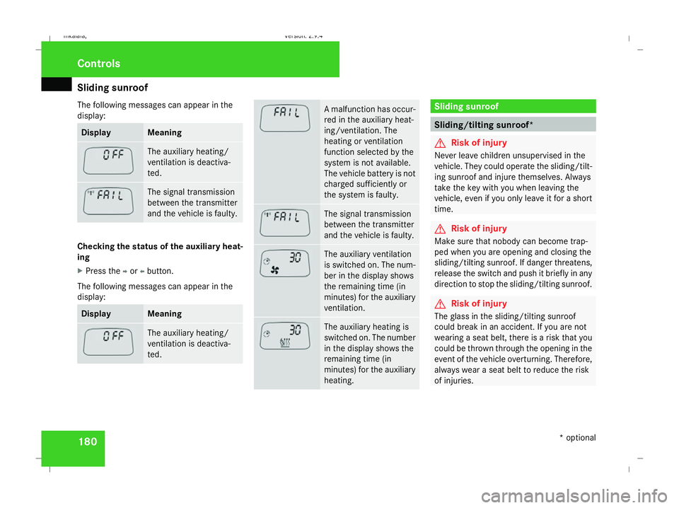
The following messages can appear in the
display: Display Meaning
The auxiliary heating/
ventilation is deactiva-
ted.
The signal transmission
between the transmitter
and the vehicle is faulty.
Checking the status of the auxiliary heat-
ing
X
Press the por obutton.
The following messages can appear in the
display: Display Meaning
The auxiliary heating/
ventilation is deactiva-
ted. A malfunction has occur-
red in the auxiliary heat-
ing/ventilation. The
heating or ventilation
function selected by the
system is not available.
The vehicle battery is not
charged sufficiently or
the system is faulty.
The signal transmission
between the transmitter
and the vehicle is faulty.
The auxiliary ventilation
is switched on. The num-
ber in the display shows
the remaining time (in
minutes) for the auxiliary
ventilation.
The auxiliary heating is
switched on. The number
in the display shows the
remaining time (in
minutes) for the auxiliary
heating. Sliding sunroof
Sliding/tilting sunroof*
G
Risk of injury
Never leave children unsupervised in the
vehicle. They could operate the sliding/tilt-
ing sunroof and injure themselves. Always
take the key with you when leaving the
vehicle, even if you only leave it for a short
time. G
Risk of injury
Make sure that nobody can become trap-
ped when you are opening and closing the
sliding/tilting sunroof. If danger threatens,
release the switch and push it briefly in any
direction to stop the sliding/tilting sunroof. G
Risk of injury
The glass in the sliding/tilting sunroof
could break in an accident. If you are not
wearing a seat belt, there is a risk that you
could be thrown through the opening in the
event of the vehicle overturning. Therefore,
always wear a seat belt to reduce the risk
of injuries. Controls
* optional
211_AKB; 2; 5, en-GB
mkalafa,
Version: 2.9.4 2008-02-29T16:57:07+01:00 - Seite 180Dateiname: 6515_3416_02_buchblock.pdf; preflight
Page 215 of 401

Features
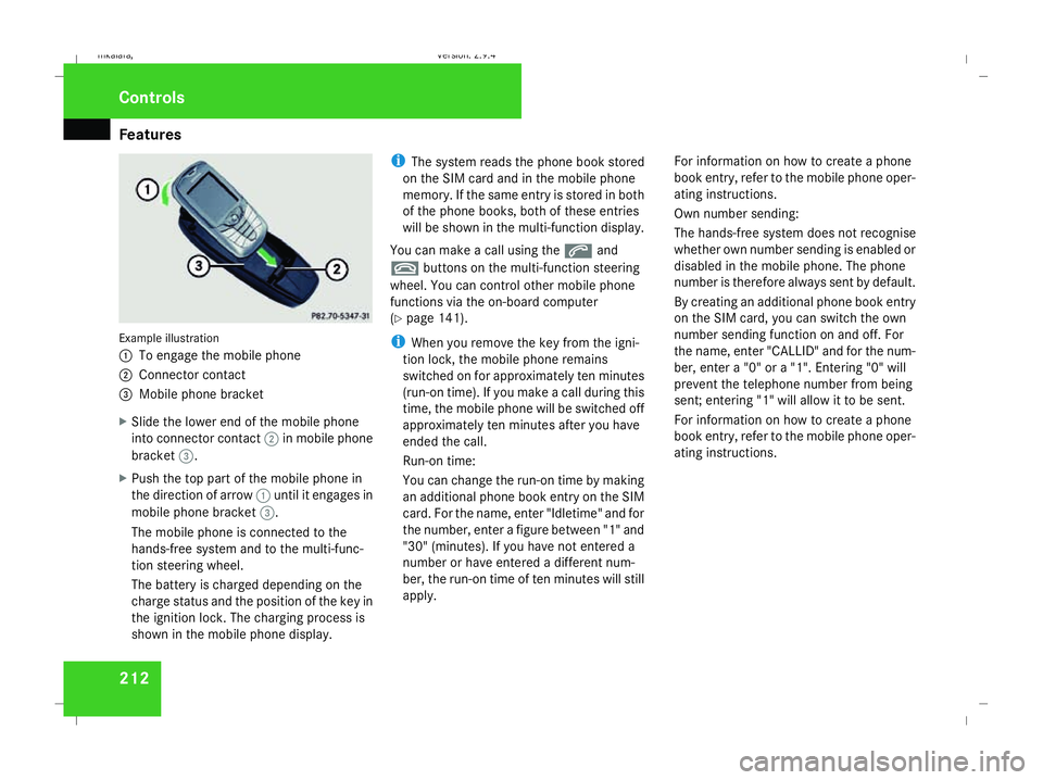
212Example illustration
1
To engage the mobile phone
2 Connector contact
3 Mobile phone bracket
X Slide the lower end of the mobile phone
into connector contact 2in mobile phone
bracket 3.
X Push the top part of the mobile phone in
the direction of arrow 1until it engages in
mobile phone bracket 3.
The mobile phone is connected to the
hands-free system and to the multi-func-
tion steering wheel.
The battery is charged depending on the
charge status and the position of the key in
the ignition lock. The charging process is
shown in the mobile phone display. i
The system reads the phone book stored
on the SIM card and in the mobile phone
memory. If the same entry is stored in both
of the phone books, both of these entries
will be shown in the multi-function display.
You can make a call using the sand
t buttons on the multi-function steering
wheel. You can control other mobile phone
functions via the on-board computer
(Y page 141).
i When you remove the key from the igni-
tion lock, the mobile phone remains
switched on for approximately ten minutes
(run-on time). If you make a call during this
time, the mobile phone will be switched off
approximately ten minutes after you have
ended the call.
Run-on time:
You can change the run-on time by making
an additional phone book entry on the SIM
card. For the name, enter "Idletime" and for
the number, enter a figure between "1" and
"30" (minutes). If you have not entered a
number or have entered a different num-
ber, the run-on time of ten minutes will still
apply. For information on how to create a phone
book entry, refer to the mobile phone oper-
ating instructions.
Own number sending:
The hands-free system does not recognise
whether own number sending is enabled or
disabled in the mobile phone. The phone
number is therefore always sent by default.
By creating an additional phone book entry
on the SIM card, you can switch the own
number sending function on and off. For
the name, enter "CALLID" and for the num-
ber, enter a "0" or a "1". Entering "0" will
prevent the telephone number from being
sent; entering "1" will allow it to be sent.
For information on how to create a phone
book entry, refer to the mobile phone oper-
ating instructions.Controls
211_AKB; 2; 5, en-GB
mkalafa,
Version: 2.9.4 2008-02-29T16:57:07+01:00 - Seite 212Dateiname: 6515_3416_02_buchblock.pdf; preflight
Page 226 of 401

Engine compartment
223
The handle for opening the bonnet is located
above the radiator grille. 2
Bonnet catch handle
X Pull handle 2of the bonnet catch out-
wards from the radiator grille and lift the
bonnet from underneath by the radiator
grille.
Closing G
Risk of injury
Make sure that nobody can become trap-
ped as you close the bonnet. X
Lower the bonnet and let it fall from a
height of approximately 20 cm.
X Check that the bonnet has engaged prop-
erly.
i If the bonnet can be raised slightly, it is
not properly engaged. Open it again and
close it with a little more force. Engine oil
Depending on driving style, the vehicle con-
sumes a maximum of 0.8 l oil per 1,000 km.
The oil consumption may be higher than this
when the vehicle is new or if you frequently
drive at high engine speeds. You can only
estimate the oil consumption after you have
driven a considerable distance.
You will find further information about engine
oil in the "Technical data" section
(Y page 385).
Checking the engine oil level To do so:R
the vehicle should be parked on level
ground.
R the engine should be switched off for at
least five minutes if the engine was at nor-
mal operating temperature.
R the engine should be switched off for at
least 30 minutes if the engine was not at
operating temperature (i.e. if you only star-
ted the engine briefly).
Via the on-board computer*
i Only possible on the E 420 CDI. On all
other models a dipstick is used to check
the engine oil level (Y page 224).
X Make sure that the key is in position 2in
the ignition lock (Y page 76).
X Press the jork button to select the
message: Engine oil level Measuring
now
The measurement takes a few seconds. You
will see one of the following messages in the
display:
R Engine oil level OK
R Add 1.0 litre to reach maximum oil
level Operation
* optional
211_AKB; 2; 5, en-GB
mkalafa,
Version: 2.9.4 2008-02-29T16:57:07+01:00 - Seite 223 ZDateiname: 6515_3416_02_buchblock.pdf; preflight
Page 228 of 401

Engine compartment
225
i
The difference in quantity between mini-
mum mark 3and maximum mark 2is
approximately 2 litres.
i On vehicles with a 4-cylinder petrol
engine and vehicles with an 8-cylinder pet-
rol engine, the difference between MIN
mark 3and MAX mark 2is approxi-
mately 1.5 litres.
Topping up the engine oil Illustration: vehicle with a petrol engine (E 500)
1
Cover Example of a vehicle with a diesel engine (E 220
CDI)
1 Cover
X Unscrew cap 1and remove it.
X Top up with the amount of oil required.
! Do not add too much oil. If too much oil
is added and the oil level is above the max-
imum mark on the dipstick, the engine or
catalytic converter could be damaged.
Have excess oil siphoned off.
X Screw cap 1onto the filler neck. H
Environmental note
When topping up the oil, take care not to
spill any. Oil must not be allowed to escape
into the soil or waterways. You would oth-
erwise be damaging the environment. Coolant
G
Risk of injury
The cooling system is pressurised. There-
fore, only unscrew the cap once the engine
has cooled down. The coolant temperature
gauge must display less than 70°C. You
could otherwise be scalded by escaping hot
coolant.
Coolant consists of water and antifreeze/cor-
rosion inhibitor. Only check the coolant level
when the vehicle is on a level surface and the
engine has cooled down. Operation
211_AKB; 2; 5, en-GB
mkalafa,
Version: 2.9.4
2008-02-29T16:57:07+01:00 - Seite 225 ZDateiname: 6515_3416_02_buchblock.pdf; preflight
Page 234 of 401

Tyres and wheels
231pressure, e.g. if the tyre is penetrated by a
foreign object.
In the event of a sudden loss of pressure,
bring the vehicle to a halt by braking care-
fully. Do not make any sudden steering
movements when doing so.
While the vehicle is in motion, the tyre pres-
sure loss warning system monitors the set
tyre pressure using the rotational speed of
the wheels. This enables the system to detect
significant pressure loss in a tyre. If the speed
of rotation of a wheel changes as a result of
a loss of pressure, a corresponding warning
message will appear in the multi-function dis-
play.
The function of the tyre pressure loss warning
system is limited or delayed if:
R snow chains are fitted to your vehicle's
tyres
R road conditions are wintry
R you are driving on sand or gravel
R you adopt a very sporty driving style (cor-
nering at high speeds or driving with high
rates of acceleration)
R you are towing a very heavy or large trailer
R you are driving with a heavy load (in the
vehicle or on the roof) Restarting the tyre pressure loss warn-
ing system Restart the tyre pressure loss warning system
if you have:
R
changed the tyre pressure
R changed the wheels or tyres
R fitted new wheels or tyres
X Before restarting, consult the table of tyre
pressures on the inside of the fuel filler flap
to ensure that the tyre pressure in all four
tyres is set correctly for the operating con-
ditions concerned.
X Also observe the notes in the section on
tyre pressures (Y page 229). G
Risk of accident
The tyre pressure loss warning system can
only give reliable warnings if you have set
the correct tyre pressure.
If an incorrect tyre pressure is set, these
incorrect values will be monitored.
A tyre with insufficient pressure results in
an instability of the vehicle when driving,
thus increasing the risk of an accident. X
Make sure that the key is in position 2in
the ignition lock.
The standard display appears in the multi-
function display (Y page 125).
X Press korj to select the tyre pres-
sure function:
Run Flat Indicator active
Menu: R-Button æ
X Press the reset button on the left of the
instrument cluster.
The following message appears in the
multi-function display:
Restart Run Flat Indicator?
Yes Cancel
If you wish to confirm the restart:
X Press the æbutton.
The following message appears in the
multi-function display:
Run Flat Indicator restarted
After a teach-in period, the tyre pressure
loss warning system will monitor the set
tyre pressures of all four tyres.
If you wish to cancel the restart:
X Press the çbutton.
or
X Wait until the message Operation
211_AKB; 2; 5, en-GB
mkalafa
,V ersion: 2.9.4
2008-02-29T16:57:07+01:00 - Seite 231 ZDateiname: 6515_3416_02_buchblock.pdf; preflight
Page 235 of 401

Tyres and wheels
232Restart Run Flat Indicator?
Yes Cancel
disappears.
The tyre pressure values stored at the last
restart will continue to be monitored. Checking the tyre pressure electroni-
cally*
The tyre pressure monitor only functions if
the correct wheel electronics are fitted to all
wheels. These monitor the pressure in all four
tyres, which you have set when restarting the
tyre pressure monitor. The monitor warns you
when the pressure drops in one or more of
the tyres. G
Risk of accident
The tyre pressure monitor does not warn
you of an incorrectly set tyre pressure. The
table on the inside of the fuel filler flap will
help you decide whether the tyre pressures
should be corrected.
The tyre pressure monitor is not able to
warn you of a sudden loss of pressure, e.g.
if the tyre is penetrated by a foreign object.
In the event of a sudden loss of pressure,
bring the vehicle to a halt by braking care-
fully. Do not make any sudden steering
movements when doing so. i
The operation of the tyre pressure moni-
tor can be affected by interference from
radio transmitting equipment (e.g. radio
headphones, two-way radios) that may be
being operated in or near the vehicle.
i If you are carrying a deflated tyre in the
vehicle, you may only reactivate the tyre
pressure monitor if:
R the deflated tyre is no longer in the vehi-
cle
R you have adjusted the tyre pressure cor-
rectly
Calling up the tyre pressure using the
on-board computer X
Make sure that the key is in position 2in
the ignition lock.
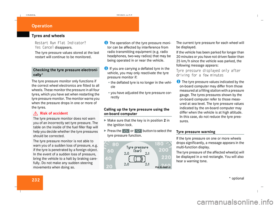
X Press the jork button to select the
tyre pressure function. The current tyre pressure for each wheel will
be displayed.
If the vehicle has been parked for longer than
20 minutes or you have not driven faster than
25 km/h since the vehicle was parked, the
following message appears:
Tyre pressure displayed only after
driving for a few minutes
i
The tyre pressure values indicated by the
on-board computer may differ from those
measured at a filling station with a pressure
gauge. The tyres pressures shown by the
on-board computer refer to those meas-
ured at sea level. The tyre pressure values
indicated by the on-board computer may
differ when the vehicle is at high altitude.
In this case, do not reduce the tyre pres-
sures.
Tyre pressure warning If the tyre pressure on one or more wheels
drops significantly, a message appears in the
multi-function display.
The tyre pressure of the affected wheel(s) will
be displayed in a red rectangle. You will also
hear a warning tone.Operation
* optional
211_AKB; 2; 5, en-GB
mkalafa
,V ersion: 2.9.4
2008-02-29T16:57:07+01:00 - Seite 232 Dateiname: 6515_3416_02_buchblock.pdf; preflight
Page 236 of 401

Tyres and wheels
233
Restarting the tyre pressure monitor In most cases, the tyre pressure monitor will
automatically detect the new reference val-
ues, e.g. if you have:
R
changed the tyre pressure
R changed the wheels or tyres
R fitted new wheels or tyres
If you wish to define the new reference values
manually:
X Use the table on the inside of the fuel filler
flap to ensure that the tyre pressure is set
correctly in all four tyres for the current
operating conditions.
Also observe the notes in the section on
tyre pressures (Y page 229).
X Make sure that the key is in position 2in
the ignition lock.
The standard display appears in the multi-
function display (Y page 125).
X Press the jork button to select the
Tyre pressure function or wait until the
following message appears:
Tyre pressure displayed only after
driving for a few minutes X
Press the reset button on the left of the
instrument cluster (Y page 243).
The following message appears in the
multi-function display: Check current
tyre pressure?
X Press the æbutton.
The following message appears in the
multi-function display:
Tyre pressure monitor restarted
The tyre pressure monitor has stored the
pressure of the tyres as a new reference
value.
If you wish to cancel the restart:
X Press the çbutton. Interchanging the wheels
G
Risk of accident
Interchange the front and rear wheels only
if they have the same dimensions: for exam-
ple size, offset, etc.
After every wheel interchange/change,
have the tightening torque checked at a
qualified specialist workshop that has the
necessary specialist knowledge and tools
to carry out the work required. Mercedes- Benz recommends that you use a
Mercedes-Benz Service Centre for this pur-
pose. In particular, work relevant to safety
or on safety-related systems must be car-
ried out at a qualified specialist workshop.
The wheels could work loose if they are not
tightened to a torque of 130 Nm.
For safety reasons, Mercedes-Benz recom-
mends that you only use wheel bolts of the
correct size which have been approved for
Mercedes-Benz vehicles.
The wheels may be interchanged every
5,000 km to 10,000 km depending on the
degree of tyre wear, provided that the vehicle
has the same size front and rear tyres. Do not
reverse the direction of tyre rotation.
The wear patterns on the front and rear tyres
differ depending on the operating conditions.
Interchange the wheels before a clear wear
pattern has formed on the tyres. The front
tyres typically wear more on the shoulders
and the rear tyres in the centre.
Clean the contact surfaces of the wheel and
the brake disc thoroughly every time a wheel
is interchanged. Check the tyre pressure and,
if necessary, restart the tyre pressure loss
warning system or the tyre pressure moni-
tor*. Operation
* optional
211_AKB; 2; 5, en-GB
mkalafa
,V ersion: 2.9.4
2008-02-29T16:57:07+01:00 - Seite 233 ZDateiname: 6515_3416_02_buchblock.pdf; preflight
Page 243 of 401

Trailer towing
240
X
Press the ball coupling in the direction of
the arrow by hand until it engages in a ver-
tical position.
Indicator lamp 2goes out.
The message Trailer tow hitch
Check locking mech. is shown in the
multi-function display until the ball cou-
pling is engaged.
X Remove the protective cap from the ball
coupling. Notes on towing a trailer
G
Risk of accident
When reversing the vehicle towards the
trailer, make sure there is nobody between
the trailer and the vehicle.
Couple and uncouple the trailer carefully. If
you do not couple the trailer to the towing
vehicle correctly, the trailer could become
detached.
Make sure that the following values are not
exceeded:
R The permitted trailer drawbar nose-
weight
R The permitted trailer load R
The permitted rear axle load of the towing
vehicle
R The maximum permissible gross vehicle
weight of both the towing vehicle and the
trailer
You will find the applicable permissible val-
ues which must not be exceeded in the
vehicle documents.
You will find the values approved by the
manufacturer on the vehicle identification
plates and those for the towing vehicle in
the “Technical data” section.
You will find installation dimensions and loads
in the "Technical data" section
(Y page 375).
The maximum permissible trailer drawbar
noseweight on the ball coupling is 76 kg
(Saloon) or 84 kg (Estate). However, the
actual noseweight must not exceed the value
given on the trailer coupling and trailer iden-
tification plates. The lowest weight applies.
! Use a noseweight as close as possible to
the maximum permissible noseweight. Do
not use a noseweight of less than 50 kg,
otherwise the trailer may come loose. Bear in mind that the payload and the rear
axle load are reduced by the actual nose-
weight.
i On vehicles without level control, the
height of the ball coupling will alter accord-
ing to the load placed on the vehicle. In this
case, you should use a trailer with a height-
adjustable drawbar.
Coupling up a trailer G
Risk of injury
Do not connect a trailer with an engaged
overrun brake. Otherwise, your hand could
become trapped between the bumper and
drawbar.
! Do not uncouple a trailer with overrun
brake between the bumper and drawbar,
otherwise your vehicle could be damaged
by the spring action of the overrun brake.
X Position the trailer level behind the vehicle.
X Couple up the trailer.
X Establish the electrical connection
between the vehicle and the trailer. Operation
211_AKB; 2; 5, en-GB
mkalafa
,V ersion: 2.9.4
2008-02-29T16:57:07+01:00 - Seite 240 Dateiname: 6515_3416_02_buchblock.pdf; preflight