2008 MERCEDES-BENZ E-CLASS ESTATE clock
[x] Cancel search: clockPage 229 of 401
Engine compartment
226
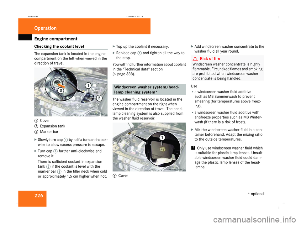
Checking the coolant level The expansion tank is located in the engine
compartment on the left when viewed in the
direction of travel. 1
Cover
2 Expansion tank
3 Marker bar
X Slowly turn cap 1by half a turn anti-clock-
wise to allow excess pressure to escape.
X Turn cap 1further anti-clockwise and
remove it.
There is sufficient coolant in expansion
tank 2if the coolant is level with the
marker bar 3in the filler neck when cold
or approximately 1.5 cm higher when hot. X
Top up the coolant if necessary.
X Replace cap 1and tighten all the way to
the stop.
You will find further information about coolant
in the "Technical data" section
(Y page 388). Windscreen washer system/head-
lamp cleaning system*
The washer fluid reservoir is located in the
engine compartment on the right when
viewed in the direction of travel. The head-
lamp cleaning system is also supplied from
the washer fluid reservoir. 1
Cover X
Add windscreen washer concentrate to the
washer fluid all year round. G
Risk of fire
Windscreen washer concentrate is highly
flammable. Fire, naked flames and smoking
are prohibited when windscreen washer
concentrate is being handled.
Use
R a windscreen washer fluid additive
such as MB Summerwash to prevent
smearing (for temperatures above freez-
ing).
R a windscreen washer fluid additive with
antifreeze properties such as MB Winter-
wash (if there is a risk of frost).
X Mix the windscreen washer fluid in a con-
tainer beforehand. Adapt the mixing ratio
to the outside temperatures.
! Only use windscreen washer fluid which
is suitable for plastic lamp lenses. Unsuit-
able windscreen washer fluid could dam-
age the plastic lamp lenses of the head-
lamps. Operation
* optional
211_AKB; 2; 5, en-GB
mkalafa,
Version: 2.9.4 2008-02-29T16:57:07+01:00 - Seite 226Dateiname: 6515_3416_02_buchblock.pdf; preflight
Page 241 of 401
Driving ab
road 238 Driving on wet roads
If water has accumulated to a certain depth
on the road surface, there is a danger of aqua-
planing occurring, even if:
R you drive at low speeds
R the tyres have adequate tread depth
For this reason, do not drive in tyre ruts, and
brake carefully. Driving on flooded roads
If you have to drive on stretches of road on
which water has collected, please bear in
mind that:
R the maximum permitted still water depth is
25 cm.
R you should drive no faster than at walking
pace.
! Note that vehicles in front or oncoming
vehicles create waves. This could mean
that the maximum permitted water depth
is exceeded.
You must observe these notes, otherwise
damage may occur to the engine, electrics
or transmission. Driving abroad
Points to remember
An extensive Mercedes-Benz Service network
is also available in other countries. You can
obtain the relevant workshop directories
from any Mercedes-Benz Service Centre.
Only low-octane fuel is available in certain
countries.
You can find further information about fuel
grades on (Y page 218). Symmetrical dipped beam
If your journey takes you to countries where
vehicles are driven on the opposite side of the
road to the country in which the vehicle is
registered, your headlamps must be switched
to symmetrical dipped beam. Oncoming traf-
fic will be dazzled less. G
Risk of injury
Vehicles with xenon headlamps*:
Xenon bulbs are under high voltage. You
could get an electric shock and be seriously
or even fatally injured if you touch the elec-
tric contacts on xenon bulbs. Do not, there-
fore, remove the cover on xenon bulbs. Do not change xenon headlamps yourself,
but have them replaced at a qualified spe-
cialist workshop which has the necessary
specialist knowledge and tools to carry out
the work required.
Mercedes-Benz recommends that you use
a Mercedes-Benz Service Centre for this
purpose. In particular, work relevant to
safety or on safety-related systems must be
carried out at a qualified specialist work-
shop.
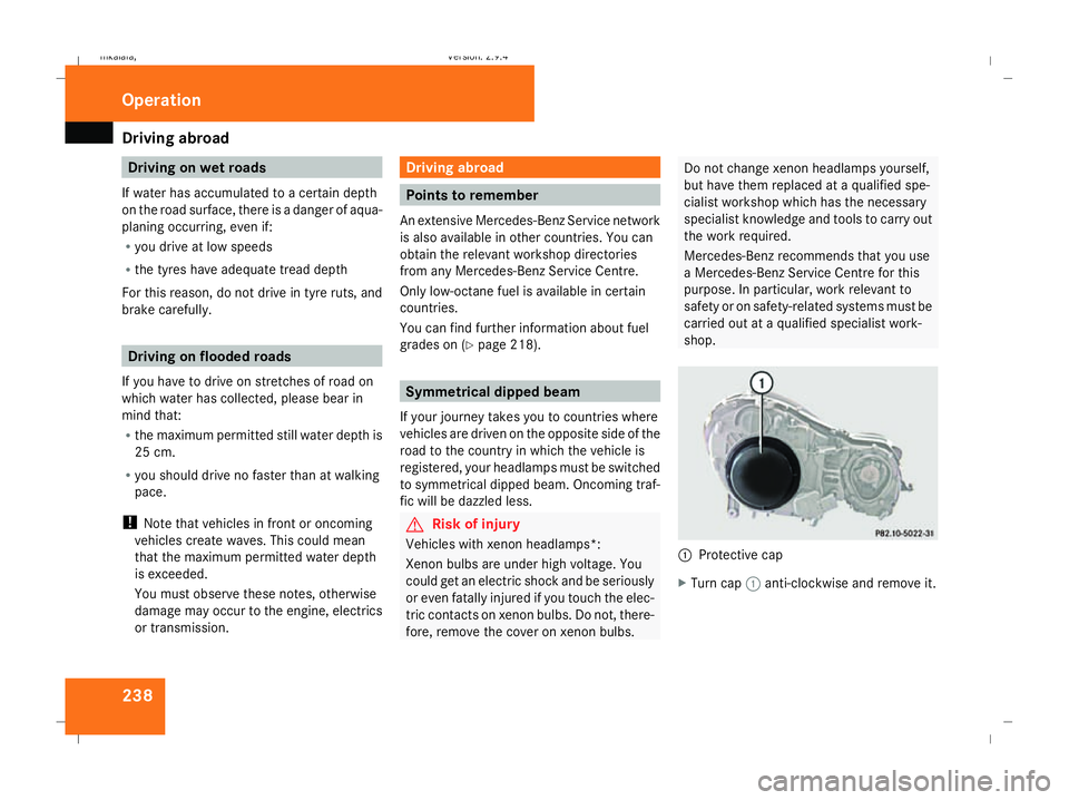
1
Protective cap
X Turn cap 1anti-clockwise and remove it. Operation
211_AKB; 2; 5, en-GB
mkalafa,
Version: 2.9.4 2008-02-29T16:57:07+01:00 - Seite 238Dateiname: 6515_3416_02_buchblock.pdf; preflight
Page 246 of 401
Service
243
Fitting the adapter
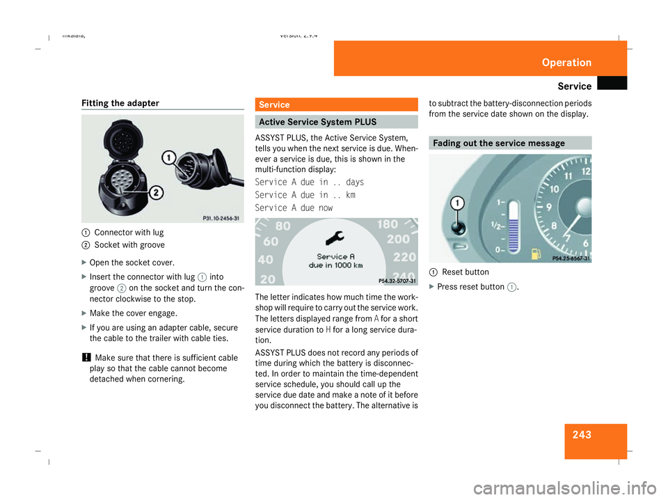
1
Connector with lug
2 Socket with groove
X Open the socket cover.
X Insert the connector with lug 1into
groove 2on the socket and turn the con-
nector clockwise to the stop.
X Make the cover engage.
X If you are using an adapter cable, secure
the cable to the trailer with cable ties.
! Make sure that there is sufficient cable
play so that the cable cannot become
detached when cornering. Service
Active Service System PLUS
ASSYST PLUS, the Active Service System,
tells you when the next service is due. When-
ever a service is due, this is shown in the
multi-function display:
Service A due in .. days
Service A due in .. km
Service A due now The letter indicates how much time the work-
shop will require to carry out the service work.
The letters displayed range from
Afor a short
service duration to Hfor a long service dura-
tion.
ASSYST PLUS does not record any periods of
time during which the battery is disconnec-
ted. In order to maintain the time-dependent
service schedule, you should call up the
service due date and make a note of it before
you disconnect the battery. The alternative is to subtract the battery-disconnection periods
from the service date shown on the display. Fading out the service message
1
Reset button
X Press reset button 1. Operation
211_AKB; 2; 5, en-GB
mkalafa,
Version: 2.9.4
2008-02-29T16:57:07+01:00 - Seite 243 ZDateiname: 6515_3416_02_buchblock.pdf; preflight
Page 257 of 401
Where will I find...?
254 Vehicle tool kit, jack and spare
wheel*
The vehicle tool kit is located in a stowage
compartment underneath the floor of the
boot/luggage compartment. G
Risk of injury
The jack is designed only to raise and hold
the vehicle for a short time while a wheel
is being changed.
If you are carrying out work on the vehicle,
you must use stands.
Make sure that the jack is placed on a firm,
non-slip and level surface. Do not use
wooden blocks or similar objects as a jack
underlay. Otherwise, the jack will not be
able to achieve its load-bearing capacity
due to the restricted height.
Do not start the engine at any time while a
wheel is being changed.
Do not lie under the vehicle when it is being
supported by the jack. If you do not raise
the vehicle as described, it could slip off the
jack (e.g. if the engine is started or a door
or the boot lid/tailgate is opened or closed)
and you could be seriously injured. i
When using the jack, you should also
observe the safety notes in the "Flat tyre"
section (Y page 324).
Saloon X
Fold up the boot floor (Y page 192).
Estate X
Open the luggage compartment floor
(Y page 193).
Vehicles with folding bench seat*
X Open the luggage compartment floor
(Y page 193).
i To reach the vehicle tool kit, the side
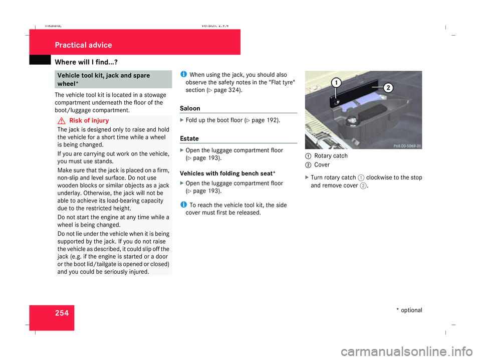
cover must first be released. 1
Rotary catch
2 Cover
X Turn rotary catch 1clockwise to the stop
and remove cover 2. Practical advice
* optional
211_AKB; 2; 5, en-GB
mkalafa,
Version: 2.9.4 2008-02-29T16:57:07+01:00 - Seite 254Dateiname: 6515_3416_02_buchblock.pdf; preflight
Page 259 of 401
Where will I find...?
256
Removing the "Minispare" emergency
spare wheel*/collapsible emergency
spare wheel or spare wheel*
X Saloon: remove the luggage well
(Y page 256).
X Estate: remove the luggage compartment
floor (Y page 194).
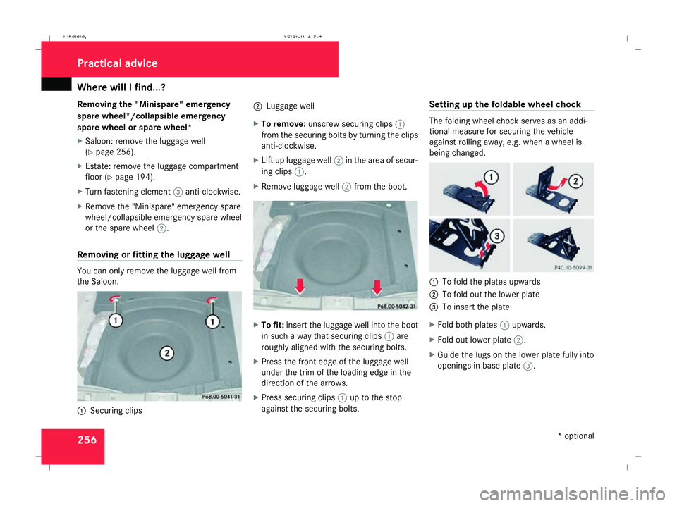
X Turn fastening element 3anti-clockwise.
X Remove the "Minispare" emergency spare
wheel/collapsible emergency spare wheel
or the spare wheel 2.
Removing or fitting the luggage well You can only remove the luggage well from
the Saloon. 1
Securing clips 2
Luggage well
X To remove: unscrew securing clips 1
from the securing bolts by turning the clips
anti-clockwise.
X Lift up luggage well 2in the area of secur-
ing clips 1.
X Remove luggage well 2from the boot. X
To fit: insert the luggage well into the boot
in such a way that securing clips 1are
roughly aligned with the securing bolts.
X Press the front edge of the luggage well
under the trim of the loading edge in the
direction of the arrows.
X Press securing clips 1up to the stop
against the securing bolts. Setting up the foldable wheel chock The folding wheel chock serves as an addi-
tional measure for securing the vehicle
against rolling away, e.g. when a wheel is
being changed.
1
To fold the plates upwards
2 To fold out the lower plate
3 To insert the plate
X Fold both plates 1upwards.
X Fold out lower plate 2.
X Guide the lugs on the lower plate fully into
openings in base plate 3.Practical advice
* optional
211_AKB; 2; 5, en-GB
mkalafa,
Version: 2.9.4 2008-02-29T16:57:07+01:00 - Seite 256Dateiname: 6515_3416_02_buchblock.pdf; preflight
Page 309 of 401
Locking/unlocking in an emergency
306 Locking/unlocking in an emergency
Emergency key
If the vehicle can no longer be unlocked or
locked with the key or the KEYLESS GO
key*, use the emergency key element.
If you use the emergency key element to
unlock and open the driver's door or the boot
lid (Saloon), the anti-theft alarm system* will
be triggered (Y page 62).
There are several ways to turn off the alarm:
X Press the korj button on the key.
or
X Insert the key into the ignition lock.
or
X Press the KEYLESS GO button* on the
selector lever. The KEYLESS GO key* must
be in the vehicle.
or
X Lock or unlock the vehicle using KEYLESS
GO*. The KEYLESS GO key* must be out-
side the vehicle. Releasing and removing the emergency
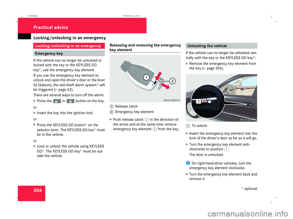
key element 1
Release catch
2 Emergency key element
X Push release catch 1in the direction of
the arrow and at the same time remove
emergency key element 2from the key. Unlocking the vehicle
If the vehicle can no longer be unlocked cen-
trally with the key or the KEYLESS GO key*:
X Remove the emergency key element from
the key (Y page 306). $
To unlock
X Insert the emergency key element into the
lock of the driver's door as far as it will go.
X Turn the emergency key element anti-
clockwise to position $.
The door is unlocked.
i On right-hand-drive vehicles, turn the
emergency key element clockwise.
X Turn the emergency key element back and
remove it. Practical advice
* optional
211_AKB; 2; 5, en-GB
mkalafa,
Version: 2.9.4 2008-02-29T16:57:07+01:00 - Seite 306Dateiname: 6515_3416_02_buchblock.pdf; preflight
Page 310 of 401
Locking/unlocking in an emergency
307Locking the vehicle
If the vehicle can no longer be locked cen-
trally with the key or the KEYLESS GO key*:
X Open the driver's door.
X Close the front-passenger door, the rear
doors and the boot lid/tailgate.
X Press the locking button (Y page 70).
X Check whether the locking knobs on the
doors are still visible. Press the locking
knobs down manually if necessary.
X Close the driver's door.
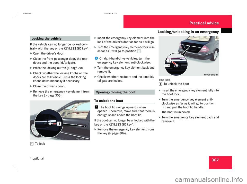
X Remove the emergency key element from
the key (Y page 306). $
To lock X
Insert the emergency key element into the
lock of the driver's door as far as it will go.
X Turn the emergency key element clockwise
as far as it will go to position $.
i On right-hand-drive vehicles, turn the
emergency key element anti-clockwise.
X Turn the emergency key element back and
remove it.
X Check whether the doors and the boot lid/
tailgate are locked. Opening/closing the boot
To unlock the boot !
The boot lid swings upwards when
opened. Therefore, make sure that there is
enough space above the boot lid.
If the boot can no longer be unlocked with the
key or the KEYLESS GO key*:
X Remove the emergency key element from
the key (Y page 306). Boot lock
$
To unlock the boot
X Insert the emergency key element fully into
the boot lock.
X Turn the emergency key element anti-
clockwise as far as it will go to position
$ and pull the boot lid handle.
The boot is unlocked.
X Turn the emergency key element back and
remove it. Practical advice
* optional
211_AKB; 2; 5, en-GB
mkalafa,
Version: 2.9.4 2008-02-29T16:57:07+01:00 - Seite 307 ZDateiname: 6515_3416_02_buchblock.pdf; preflight
Page 317 of 401
Changing the bulbs
314 Changing the front bulbs
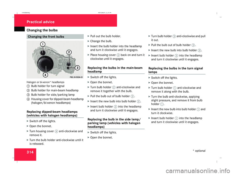
Halogen or bi-xenon* headlamps
1
Bulb holder for turn signal
2 Bulb holder for main-beam headlamp
3 Bulb holder for side/parking lamp
4 Housing cover for dipped-beam headlamp
(halogen/bi-xenon headlamps)
Replacing dipped-beam headlamps
(vehicles with halogen headlamps) X
Switch off the lights.
X Open the bonnet.
X Turn housing cover 4anti-clockwise and
remove it.
X Turn the bulb holder anti-clockwise until it
is released. X
Pull out the bulb holder.
X Change the bulb.
X Insert the bulb holder into the headlamp
and turn it clockwise until it engages.
X Place housing cover 4back on and turn it
clockwise until it engages.
Replacing the bulbs in the main-beam
headlamp X
Switch off the lights.
X Open the bonnet.
X Turn bulb holder 2anti-clockwise and
remove it together with the bulb.
X Pull the bulb out of bulb holder 2.
X Insert the new bulb into bulb holder 2.
X Insert bulb holder 2into the headlamp
and turn it clockwise until it engages.
Replacing the bulb in the side lamp/
parking lamp (vehicles with halogen
headlamps) X
Switch off the lights.
X Open the bonnet. X
Turn bulb holder 3anti-clockwise and pull
it out.
X Pull the bulb out of bulb holder 3.
X Insert the new bulb into bulb holder 3.
X Insert bulb holder 3into the headlamp
and turn it clockwise until it engages.
Replacing the bulbs in the turn signal
lamps X
Switch off the lights.
X Open the bonnet.
X Turn bulb holder 1anti-clockwise and
remove it along with the bulb.
X Turn the bulb anti-clockwise, applying
slight pressure, and remove it from bulb
holder 1.
X Insert the new bulb into bulb holder 1and
turn it clockwise.
X Insert bulb holder 1into the headlamp
and turn it clockwise until it engages. Practical advice
* optional
211_AKB; 2; 5, en-GB
mkalafa,
Version: 2.9.4 2008-02-29T16:57:07+01:00 - Seite 314Dateiname: 6515_3416_02_buchblock.pdf; preflight