2008 MERCEDES-BENZ E-CLASS ESTATE charging
[x] Cancel search: chargingPage 7 of 401
4
Automatic transmission Display
message
. . . . . . . . . . . . . . . . . . . . . . .261
Auxiliary heating . . . . . . . . . . ..177, 304
Display message . . . . . . . . . . . . . .280
Remote control . . . . . . . . . . . . . . .178
Setting (on-board computer) . . . . .133
Auxiliary ventilation . . . . . . . . . . . ..177
Axle load, maximum permissible
. . . . . . . . . . . . . .370, 371, 372, 373, 374 B
Ball coupling Folding in . . . . . . . . . . . . . . . . . . . .241
Folding out . . . . . . . . . . . . . . . . . . .239
BAS (Brake Assist) . . . . . . . . . . . . . . ..59
Battery Changing (auxiliary heating
remote control) . . . . . . . . . . . . . . .311
Changing (key ).. . . . . . . . . . . . . . .310
Changing (KEYLESS GO key) . . . . .310
Charging . . . . . . . . . . . . . . . . . . . . .332
Checking (key ).. . . . . . . . . . . . . . .310
Checking (KEYLESS GO key) . . . . .310
Check lamp (key ).. . . . . . . . . . . . .310
Check lamp (KEYLESS GO key) . . . . . . . . . . . . . . . . . . . . . . . . .69, 310
Disconnecting . . . . . . . . . . . . . . . .331
Display message . . . . . . . . . . . . . .266
Maintenance (vehicle ).. . . . . . . ..329
Reconnecting . . . . . . . . . . . . . . . . .333 Removing/fitting . . . . . . . . . . . . .
.332
Vehicle battery . . . . . . . . . . . . . . . .329
Voltage (on-board computer) . . . . .127
Belt force limiters
Activatio n.. . . . . . . . . . . . . . . . . . . .41
Belt height adjustment . . . . . . . . . . ..97
Belt reel (Easy-Pack fix kit) . . . . . . ..203
Belt tensioners Activatio n.. . . . . . . . . . . . . . . . . . . .41
Belt warning . . . . . . . . . . . . . . . . . . . . .97
Bonnet Bonnet catch . . . . . . . . . . . . . . . . .223
Display message . . . . . . . . . . . . . .267
Opening/closing . . . . . . . . . . . . . .222
Bonnet release lever
Release lever . . . . . . . . . . . . . . . . .222
Boot
Emergency release . . . . . . . . . . . . .307
Locking separatel y.. . . . . . . . . . . . .72
Opening/closing (manually) . . . . . . .70
Boot/luggage compartment
Opening/closing (automatically )...73
Boot lid
Display message . . . . . . . . . . . . . .266
Brake
Warning lamp . . . . . . . . . . . . . . . . .286
Brake Assist
see BAS
Brake fluid . . . . . . . . . . . . . . . . . . . . .390
Display message . . . . . . . . . . . . . .270 Brake lamps
Adaptive . . . . . . . . . . . . . . . . . . . . . .59
Display message . . . . . . . . . . . . . .274
Brake system
Display message . . . . . . . . . .268, 269
Parking brake . . . . . . . . . . . . . . . . .113
Bulb
Changing . . . . . . . . . . . . . . . .314, 315
Dipped-beam headlamps . . . . . . . .314
Licence plate lamp . . . . . . . . . . . . .315
Main-beam headlamps . . . . . . . . . .314
Parking lamp . . . . . . . . . . . . . . . . .314
Side lamp . . . . . . . . . . . . . . . . . . . .314
Turn signal lamp . . . . . . . . . . . . . . .314
see Lamp
Bulbs
Overview . . . . . . . . . . . . . . . . . . . .312 C
Calling up a malfunction see Message memory menu
Care . . . . . . . . . . . . . . . . . . . . . . . . . . .244
Automatic car wash . . . . . . . . . . . .245
Distronic . . . . . . . . . . . . . . . . . . . .248
Headlamps . . . . . . . . . . . . . . . . . . .246
High-pressure cleaners . . . . . . . . .245
Parktroni c.. . . . . . . . . . . . . . . . . .248
Plastic trim . . . . . . . . . . . . . . . . . . .247
Rear window . . . . . . . . . . . . . . . . .246
Side windows . . . . . . . . . . . . . . . . .246 Index
211_AKB; 2; 5, en-GB
mkalafa,
Version: 2.9.4 2008-02-29T16:57:07+01:00 - Seite 4Dateiname: 6515_3416_02_buchblock.pdf; preflight
Page 102 of 401
Lights
99Lights
Light switch
For reasons of safety, Mercedes-Benz recom-
mends that you drive with the lights switched
on even during the daytime. In some coun-
tries, daytime operation of headlamps varies
due to legal requirements and self-imposed
obligations. In these countries, the dipped-
beam headlamps are automatically switched
on when the engine is started.
i If you drive in countries in which traffic
drives on the opposite side of the road to
the country where the vehicle is registered,
oncoming traffic may be dazzled by the
asymmetrical dipped-beam headlamps.
Have the headlamps changed to symmet-
rical dipped beam when driving in these
countries. You can obtain information
about this from any Mercedes-Benz Service
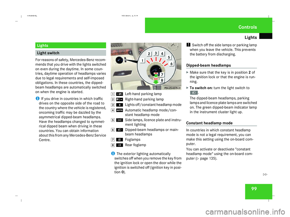
Centre. $
a
Left-hand parking lamp
% g
Right-hand parking lamp
& M
Lights off/constant headlamp mode
( U
Automatic headlamp mode/con-
stant headlamp mode
) C
Side lamps, licence plate and instru-
ment lighting
* B
Dipped-beam headlamps or main-
beam headlamps
, ¥
Foglamps
. †
Rear foglamp
i The exterior lighting automatically
switches off when you remove the key from
the ignition lock or open the door while the
ignition is switched off (ignition key in posi-
tion 0). !
Switch off the side lamps or parking lamp
when you leave the vehicle. This prevents
the battery from discharging.
Dipped-beam headlamps X
Make sure that the key is in position 2of
the ignition lock or that the engine is run-
ning.
X To switch on: turn the light switch to
B.
The dipped-beam headlamps, parking
lamps and licence plate lamps are switched
on. The green dipped-beam indicator lamp
in the instrument cluster light up.
Constant headlamp mode In countries in which constant headlamp
mode is not a legal requirement, you can
make this setting using the on-board com-
puter.
You can activate or deactivate "constant
headlamp mode" using the on-board com-
puter (Y page 135). Controls
211_AKB; 2; 5, en-GB
mkalafa,
Version: 2.9.4 2008-02-29T16:57:07+01:00 - Seite 99 ZDateiname: 6515_3416_02_buchblock.pdf; preflight
Page 215 of 401
Features
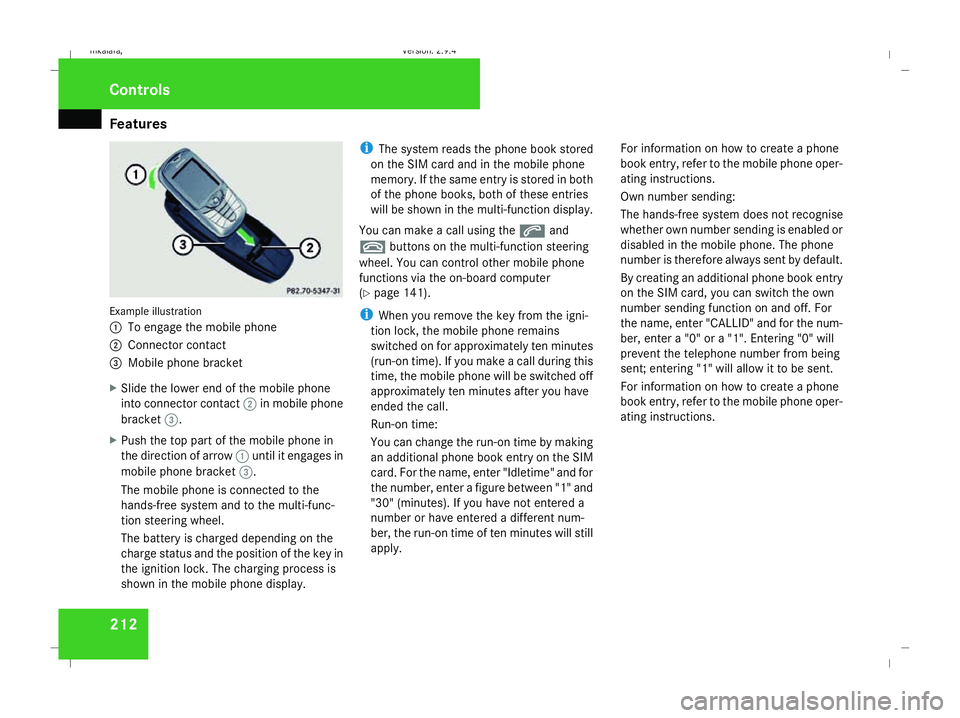
212Example illustration
1
To engage the mobile phone
2 Connector contact
3 Mobile phone bracket
X Slide the lower end of the mobile phone
into connector contact 2in mobile phone
bracket 3.
X Push the top part of the mobile phone in
the direction of arrow 1until it engages in
mobile phone bracket 3.
The mobile phone is connected to the
hands-free system and to the multi-func-
tion steering wheel.
The battery is charged depending on the
charge status and the position of the key in
the ignition lock. The charging process is
shown in the mobile phone display. i
The system reads the phone book stored
on the SIM card and in the mobile phone
memory. If the same entry is stored in both
of the phone books, both of these entries
will be shown in the multi-function display.
You can make a call using the sand
t buttons on the multi-function steering
wheel. You can control other mobile phone
functions via the on-board computer
(Y page 141).
i When you remove the key from the igni-
tion lock, the mobile phone remains
switched on for approximately ten minutes
(run-on time). If you make a call during this
time, the mobile phone will be switched off
approximately ten minutes after you have
ended the call.
Run-on time:
You can change the run-on time by making
an additional phone book entry on the SIM
card. For the name, enter "Idletime" and for
the number, enter a figure between "1" and
"30" (minutes). If you have not entered a
number or have entered a different num-
ber, the run-on time of ten minutes will still
apply. For information on how to create a phone
book entry, refer to the mobile phone oper-
ating instructions.
Own number sending:
The hands-free system does not recognise
whether own number sending is enabled or
disabled in the mobile phone. The phone
number is therefore always sent by default.
By creating an additional phone book entry
on the SIM card, you can switch the own
number sending function on and off. For
the name, enter "CALLID" and for the num-
ber, enter a "0" or a "1". Entering "0" will
prevent the telephone number from being
sent; entering "1" will allow it to be sent.
For information on how to create a phone
book entry, refer to the mobile phone oper-
ating instructions.Controls
211_AKB; 2; 5, en-GB
mkalafa,
Version: 2.9.4 2008-02-29T16:57:07+01:00 - Seite 212Dateiname: 6515_3416_02_buchblock.pdf; preflight
Page 333 of 401
Battery
330 step out of the vehicle first and touch the
bodywork.
R Do not wipe the battery using a cloth. The
battery may explode as a result of elec-
trostatic charge or due to flying sparks.
! Switch the engine off and remove the key
before unscrewing or disconnecting the
terminal clamps from the battery. You may
otherwise destroy electronic components
such as the alternator.
i Mercedes-Benz recommends that you
have all work involving the battery, e.g.
removing, charging and replacing, carried
out at a qualified specialist workshop, e.g.
a Mercedes-Benz Service Centre.
Installation location of the battery Your vehicle is equipped with a battery in the
boot. It is located under the cover in the spare
wheel well.
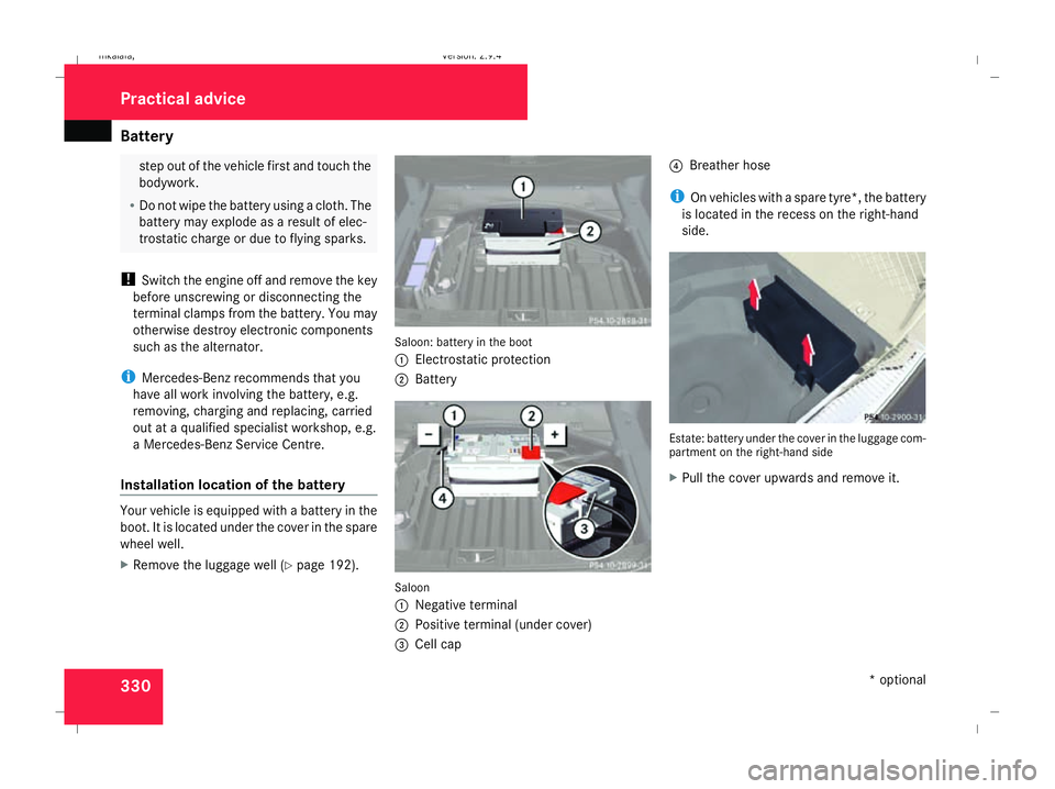
X Remove the luggage well (Y page 192). Saloon: battery in the boot
1
Electrostatic protection
2 Battery Saloon
1
Negative terminal
2 Positive terminal (under cover)
3 Cell cap 4
Breather hose
i On vehicles with a spare tyre*, the battery
is located in the recess on the right-hand
side. Estate: battery under the cover in the luggage com-
partment on the right-hand side
X
Pull the cover upwards and remove it. Practical advice
* optional
211_AKB; 2; 5, en-GB
mkalafa,
Version: 2.9.4 2008-02-29T16:57:07+01:00 - Seite 330Dateiname: 6515_3416_02_buchblock.pdf; preflight
Page 335 of 401
Battery
332
X
Open the boot/luggage compartment.
X Remove the cover (Y page 256).
X Remove the battery cover.
X Remove the negative terminal clamp from
the battery.
X Remove the cover from the positive termi-
nal clamp.
X Remove the positive terminal clamp from
the battery.
X Disconnect the breather hose. Removing the battery
Saloon X
Disconnect the battery ( Ypage 331).
X Loosen the bolt which holds the battery in
place.
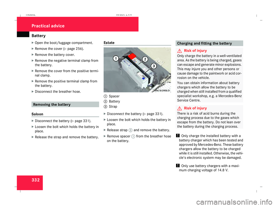
X Release the strap and remove the battery. Estate 1
Spacer
2 Battery
3 Strap
X Disconnect the battery ( Ypage 331).
X Loosen the bolt which holds the battery in
place.
X Release strap 3and remove the battery.
X Remove spacer 1from the breather hose
on the battery. Charging and fitting the battery
G
Risk of injury
Only charge the battery in a well-ventilated
area. As the battery is being charged, gases
can escape and generate minor explosions.
This may injure you and other persons or
cause damage to the paintwork or acid cor-
rosion on the vehicle.
You can obtain information about battery
chargers which allow the battery to be
charged when still installed from a qualified
specialist workshop, e.g. a Mercedes-Benz
Service Centre. G
Risk of injury
There is a risk of acid burns during the
charging process due to the gases which
escape from the battery. Do not lean over
the battery during the charging process.
! Only charge the installed battery with a
battery charger which has been tested and
approved by Mercedes-Benz. These battery
chargers allow the battery to be charged
while it is still installed. Otherwise, the vehi-
cle's electronic system may be damaged.
! Only use battery chargers with a maxi-
mum charging voltage of 14.8 V. Practical advice
211_AKB; 2; 5, en-GB
mkalafa,
Version: 2.9.4 2008-02-29T16:57:07+01:00 - Seite 332Dateiname: 6515_3416_02_buchblock.pdf; preflight