2008 INFINITI QX56 oil level
[x] Cancel search: oil levelPage 2616 of 4083
MA-18
< ON-VEHICLE MAINTENANCE >
ENGINE MAINTENANCE
2. Disconnect the harness connector, then remove the air cleaner case (upper).
3. Remove the air cleaner filter from the air cleaner case (lower).
4. Install the new air cleaner filter in the air cleaner case (lower).
5. Install the air cleaner case (upper) and connect the harness connector.
6. Install the air duct and resonator assembly.
Changing Engine OilINFOID:0000000001606175
WARNING:
• Be careful not to burn yourself, as the engine and engine oil are hot.
• Prolonged and repeated contact with used engine oil may cause skin cancer; try to avoid direct skin
contact with used oil. If skin contact is made, wash thoroughly with soap or hand cleaner as soon as
possible.
1. Warm up the engine, and check for any oil leaks.
2. Stop the engine and wait for at least 10 minutes.
3. Remove the oil drain plug and oil filler cap to drain the old oil.
4. Install a new washer on the oil drain plug, then install the oil drain plug in the oil pan.
CAUTION:
Clean the drain plug and install with a new washer.
5. Refill the engine with new specified engine oil.
CAUTION:
The refill capacity depends on th e oil temperature and drain time. Use the “Refill oil capacity” val-
ues as a reference and check the oil level using th e dipstick when filling the engine with oil.
6. Warm up the engine and check the area around the dr ain plug and oil filter for any oil leaks.
7. Stop the engine and wait for more than 10 minutes.
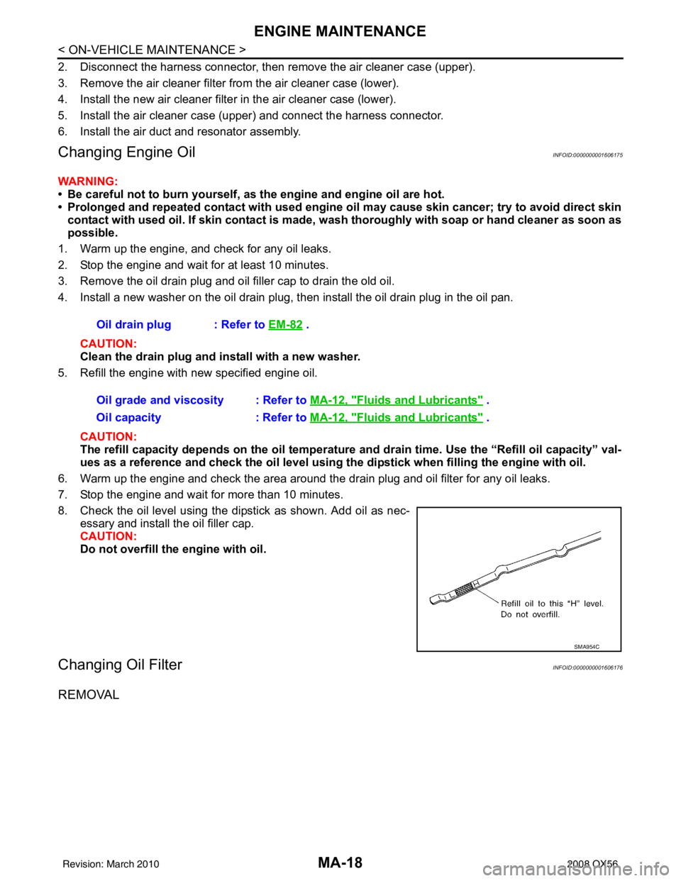
8. Check the oil level using the dipstick as shown. Add oil as nec- essary and install the oil filler cap.
CAUTION:
Do not overfill the engine with oil.
Changing Oil FilterINFOID:0000000001606176
REMOVAL
Oil drain plug : Refer to EM-82 .
Oil grade and viscosity : Refer to MA-12, "
Fluids and Lubricants" .
Oil capacity : Refer to MA-12, "
Fluids and Lubricants" .
SMA954C
Revision: March 2010 2008 QX56
Page 2617 of 4083
ENGINE MAINTENANCEMA-19
< ON-VEHICLE MAINTENANCE >
C
DE
F
G H
I
J
K L
M B
MA
N
O A
1. Remove the engine front undercover using power tool.
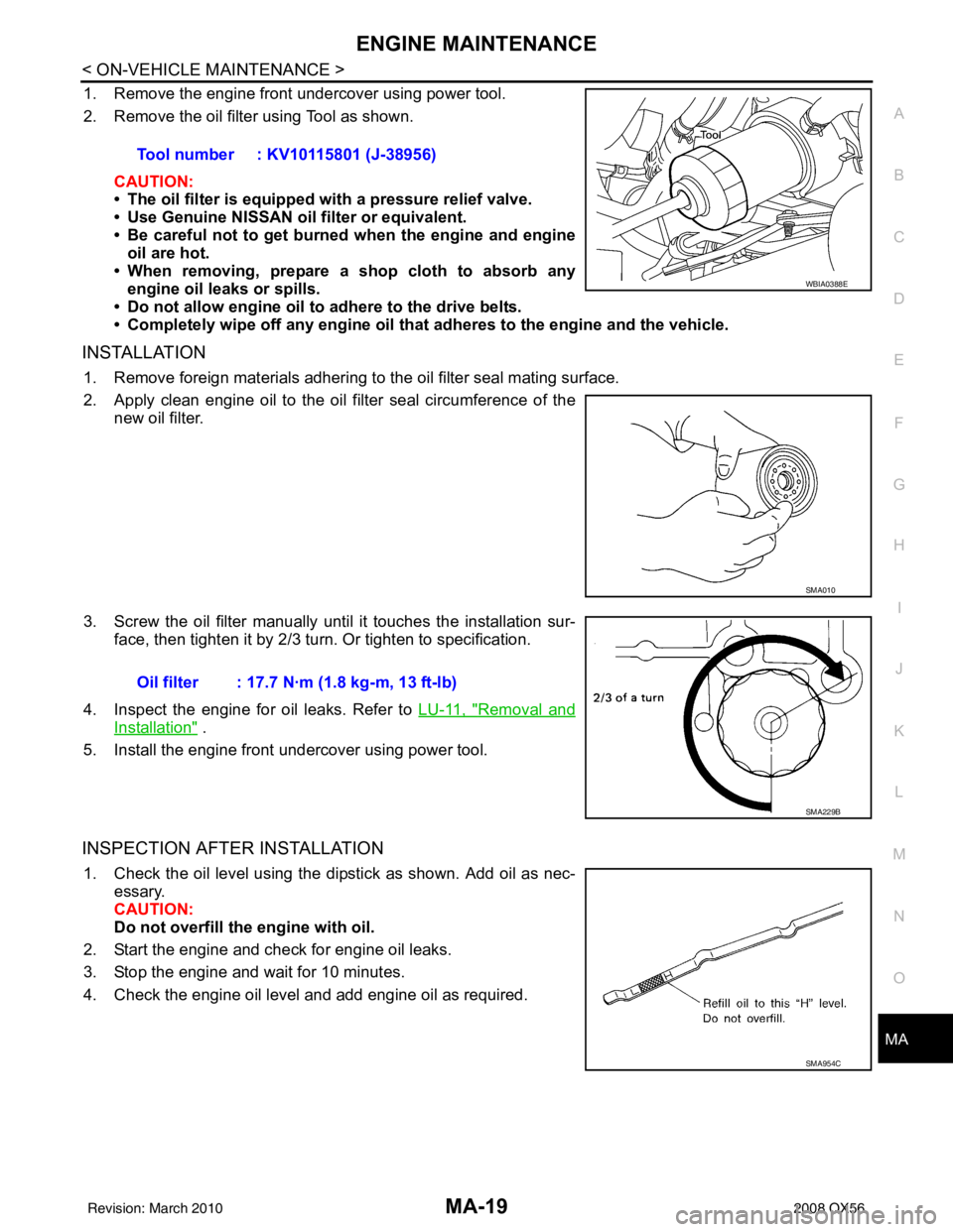
2. Remove the oil filter using Tool as shown.
CAUTION:
• The oil filter is equipped with a pressure relief valve.
• Use Genuine NISSAN oil filter or equivalent.
• Be careful not to get burned when the engine and engine
oil are hot.
• When removing, prepare a s hop cloth to absorb any
engine oil leaks or spills.
• Do not allow engine oil to adhere to the drive belts.
• Completely wipe off any engine oil that adheres to the engine and the vehicle.
INSTALLATION
1. Remove foreign materials adhering to the oil filter seal mating surface.
2. Apply clean engine oil to the oil filter seal circumference of the
new oil filter.
3. Screw the oil filter manually unt il it touches the installation sur-
face, then tighten it by 2/3 turn. Or tighten to specification.
4. Inspect the engine for oil leaks. Refer to LU-11, "
Removal and
Installation" .
5. Install the engine front undercover using power tool.
INSPECTION AFTER INSTALLATION
1. Check the oil level using the dipstick as shown. Add oil as nec- essary.
CAUTION:
Do not overfill th e engine with oil.
2. Start the engine and check for engine oil leaks.
3. Stop the engine and wait for 10 minutes.
4. Check the engine oil level and add engine oil as required. Tool number : KV10115801 (J-38956)
WBIA0388E
SMA010
Oil filter : 17.7 N·m (1.8 kg-m, 13 ft-lb)
SMA229B
SMA954C
Revision: March 2010
2008 QX56
Page 2623 of 4083
CHASSIS AND BODY MAINTENANCEMA-25
< ON-VEHICLE MAINTENANCE >
C
DE
F
G H
I
J
K L
M B
MA
N
O A
10. Tighten the level gauge bolt to specification.
Changing Automatic Transmission Fluid (ATF)INFOID:0000000001606182
1. Drive the vehicle to warm up the ATF to 80
° C (176 ° F).
2. Stop the engine.
3. Remove the ATF level gauge bolt.
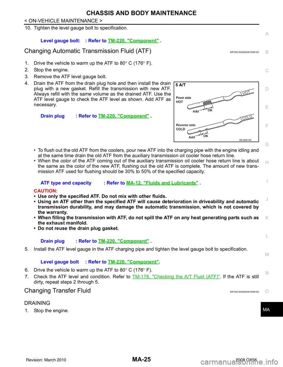
4. Drain the ATF from the drain plug hole and then install the drain plug with a new gasket. Refill the transmission with new ATF.
Always refill with the same volume as the drained ATF. Use the
ATF level gauge to check the ATF level as shown. Add ATF as
necessary.
• To flush out the old ATF from the coolers, pour new ATF into the charging pipe with the engine idling and
at the same time drain the old ATF from the aux iliary transmission oil cooler hose return line.
• When the color of the ATF coming out of the auxiliary transmission oil cooler hose return line is about
the same as the color of the new ATF, flushing out the old ATF is complete. The amount of new trans-
mission ATF used for flushing should be 30% to 50% of the specified capacity.
CAUTION:
• Use only the specified ATF. Do not mix with other fluids.
• Using an ATF other than the speci fied ATF will cause deterioration in driveability and automatic
transmission durability, and may damage the au tomatic transmission, which is not covered by
the warranty.
• When filling the transmission with ATF, do not spill the ATF on any heat generating parts such as the exhaust manifold.
• Do not reuse the drain plug gasket.
5. Install the ATF level gauge in the ATF charging pipe and tighten the level gauge bolt to specification.
6. Drive the vehicle to warm up the ATF to 80 ° C (176 ° F).
7. Check the ATF level and condition. Refer to TM-178, "
Checking the A/T Fluid (ATF)". If the ATF is still
dirty, repeat steps 2 through 5.
Changing Transfer FluidINFOID:0000000001606183
DRAINING
1. Stop the engine. Level gauge bolt: : Refer to
TM-220, "
Component" .
Drain plug : Refer to TM-220, "
Component" .
WLIA0014E
ATF type and capacity : Refer to MA-12, "Fluids and Lubricants" .
Drain plug : Refer to TM-220, "
Component" .
Level gauge bolt : Refer to TM-220, "
Component".
Revision: March 2010 2008 QX56
Page 2624 of 4083
MA-26
< ON-VEHICLE MAINTENANCE >
CHASSIS AND BODY MAINTENANCE
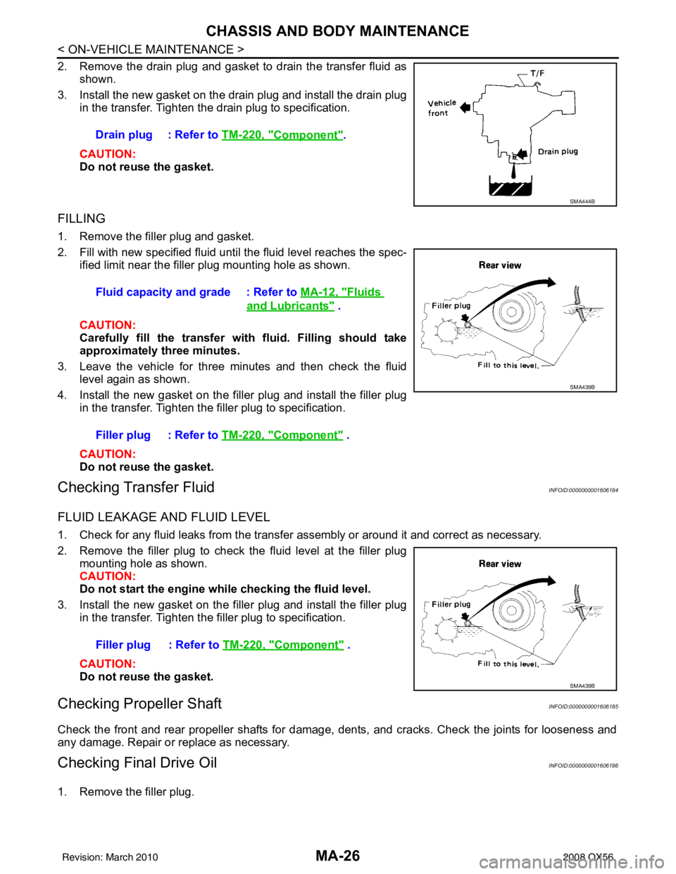
2. Remove the drain plug and gasket to drain the transfer fluid asshown.
3. Install the new gasket on the drain plug and install the drain plug in the transfer. Tighten the drain plug to specification.
CAUTION:
Do not reuse the gasket.
FILLING
1. Remove the filler plug and gasket.
2. Fill with new specified fluid until the fluid level reaches the spec-
ified limit near the filler plug mounting hole as shown.
CAUTION:
Carefully fill the transfer wi th fluid. Filling should take
approximately three minutes.
3. Leave the vehicle for three minutes and then check the fluid level again as shown.
4. Install the new gasket on the filler plug and install the filler plug in the transfer. Tighten the filler plug to specification.
CAUTION:
Do not reuse the gasket.
Checking Transfer FluidINFOID:0000000001606184
FLUID LEAKAGE AND FLUID LEVEL
1. Check for any fluid leaks from the transfer assembly or around it and correct as necessary.
2. Remove the filler plug to check the fluid level at the filler plugmounting hole as shown.
CAUTION:
Do not start the engine wh ile checking the fluid level.
3. Install the new gasket on the filler plug and install the filler plug in the transfer. Tighten the filler plug to specification.
CAUTION:
Do not reuse the gasket.
Checking Propeller ShaftINFOID:0000000001606185
Check the front and rear propeller shafts for damage, dents, and cracks. Check the joints for looseness and
any damage. Repair or replace as necessary.
Checking Final Drive OilINFOID:0000000001606186
1. Remove the filler plug. Drain plug : Refer to
TM-220, "
Component".
SMA444B
Fluid capacity and grade : Refer to MA-12, "Fluids
and Lubricants" .
Filler plug : Refer to TM-220, "
Component" .
SMA439B
Filler plug : Refer to TM-220, "Component" .
SMA439B
Revision: March 2010 2008 QX56
Page 2625 of 4083

CHASSIS AND BODY MAINTENANCEMA-27
< ON-VEHICLE MAINTENANCE >
C
DE
F
G H
I
J
K L
M B
MA
N
O A
2. Check the oil level as shown. A
dd the specified oil as necessary.
NOTE:
Rear final drive shown, front final drive similar
3. Install the filler plug and tighten to specification.
Changing Final Drive OilINFOID:0000000001606187
1. Remove the filler plug.
2. Remove the drain plug and drain the final drive oil.
3. Apply sealant to the drain plug threads. • Use High Performance Thread Sealant or equivalent. Refer to GI-15, "
Recommended Chemical Prod-
ucts and Sealants" .
4. Install the drain plug and tighten to specification.
5. Refill the rear final drive with new specified oil.
6. Check the oil level. NOTE:
Rear final drive shown, front final drive similar
7. Install the filler plug and tighten to specification.
AdjustmentINFOID:0000000006059786
BALANCING WHEELS (ADH ESIVE WEIGHT TYPE)
Preparation Before Adjustment
Remove inner and outer balance weights from the r oad wheel using releasing agent, remove double-faced
adhesive tape from the road wheel.
CAUTION:
• Be careful not scratch the road wheel during removal. Oil grade and viscosity : Refer to
MA-12, "
Fluids and
Lubricants" .
LLIA0068E
Filler plug : Refer to DLN-214, "Disassembly and Assembly" (FFD), DLN-251, "Disassem-
bly and Assembly" (RFD).
Drain plug : Refer to DLN-214, "
Disassembly and Assembly" (FFD), DLN-251, "Dis-
assembly and Assembly" (RFD).
Oil grade and capacity : Refer to MA-12, "
Fluids and Lubricants" .
LLIA0068E
Filler plug : Refer to DLN-214, "Disassembly and Assembly" (FFD), DLN-251, "Disassem-
bly and Assembly" (RFD).
Revision: March 2010 2008 QX56
Page 2629 of 4083
CHASSIS AND BODY MAINTENANCEMA-31
< ON-VEHICLE MAINTENANCE >
C
DE
F
G H
I
J
K L
M B
MA
N
O A
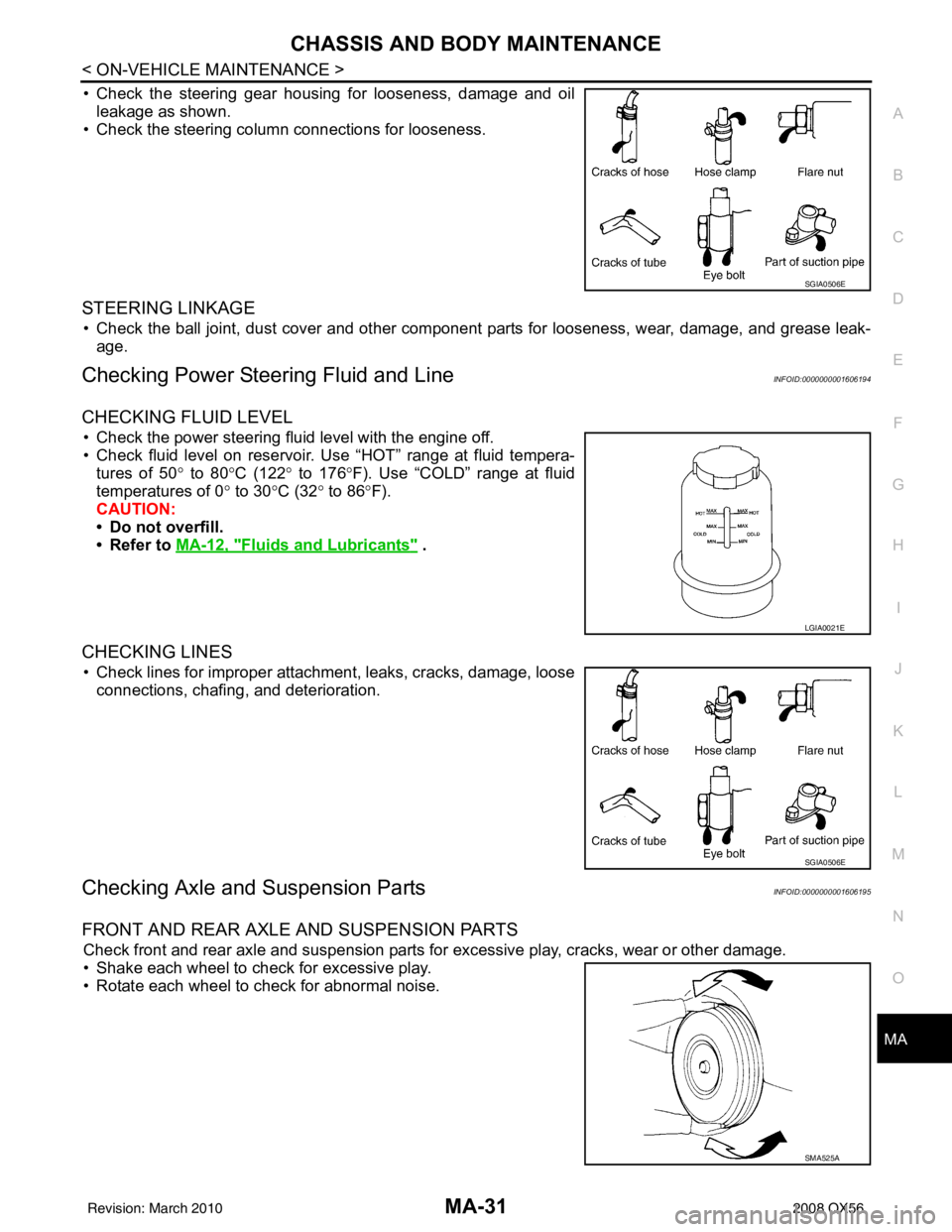
• Check the steering gear housing for looseness, damage and oil
leakage as shown.
• Check the steering column connections for looseness.
STEERING LINKAGE
• Check the ball joint, dust cover and other component parts for looseness, wear, damage, and grease leak-
age.
Checking Power Steering Fluid and LineINFOID:0000000001606194
CHECKING FLUID LEVEL
• Check the power steering fluid level with the engine off.
• Check fluid level on reservoir. Use “HOT” range at fluid tempera- tures of 50 ° to 80° C (122° to 176° F). Use “COLD” range at fluid
temperatures of 0 ° to 30° C (32° to 86° F).
CAUTION:
• Do not overfill.
• Refer to MA-12, "
Fluids and Lubricants" .
CHECKING LINES
• Check lines for improper attachment, leaks, cracks, damage, loose
connections, chafing, and deterioration.
Checking Axle and Suspension PartsINFOID:0000000001606195
FRONT AND REAR AXLE AND SUSPENSION PARTS
Check front and rear axle and suspension parts for excessive play, cracks, wear or other damage.
• Shake each wheel to check for excessive play.
• Rotate each wheel to check for abnormal noise.
SGIA0506E
LGIA0021E
SGIA0506E
SMA525A
Revision: March 2010 2008 QX56
Page 2647 of 4083

MWI-2
INFORMATION DISPLAY .........................................19
INFORMATION DISPLAY : System Diagram .........20
INFORMATION DISPLAY : System Description ....20
INFORMATION DISPLAY : Component Parts Lo-
cation ................................................................... ...
21
INFORMATION DISPLAY : Component Descrip-
tion ....................................................................... ...
21
COMPASS .........................................................22
Description ........................................................... ...22
DIAGNOSIS SYSTEM (METER) .......................24
Diagnosis Description .......................................... ...24
CONSULT-III Function (METER/M&A) ................ ...25
COMPONENT DIAGNOSIS ........................28
DTC U1000 CAN COMMUNICATION ............ ...28
DTC Logic ............................................................ ...28
Diagnosis Procedure .............................................28
DTC B2205 VEHICLE SPEED CIRCUIT ...........29
Description ........................................................... ...29
DTC Logic ...............................................................29
Diagnosis Procedure .............................................29
POWER SUPPLY AND GROUND CIRCUIT .....30
COMBINATION METER ........................................ ...30
COMBINATION METER : Diagnosis Procedure ....30
BCM (BODY CONTROL MODULE) ...................... ...30
BCM (BODY CONTROL MODULE) : Diagnosis
Procedure ...............................................................
31
IPDM E/R (INTELLIGENT POWER DISTRIBU-
TION MODULE ENGINE ROOM) .......................... ...
31
IPDM E/R (INTELLIGENT POWER DISTRIBU-
TION MODULE ENGINE ROOM) : Diagnosis Pro-
cedure .....................................................................
31
FUEL LEVEL SENSOR SIGNAL CIRCUIT .......33
Description ........................................................... ...33
Component Function Check ...................................33
Diagnosis Procedure .............................................33
Component Inspection ............................................34
OIL PRESSURE SWITCH SIGNAL CIRCUIT ...35
Description ..............................................................35
Component Function Check ...................................35
Diagnosis Procedure ..............................................35
Component Inspection ............................................35
PARKING BRAKE SWITCH SIGNAL CIR-
CUIT ...................................................................
36
Description ........................................................... ...36
Component Function Check ...................................36
Diagnosis Procedure ..............................................36
Component Inspection ............................................36
WASHER LEVEL SWITCH SIGNAL CIRCUIT ...37
Description ........................................................... ...37
Diagnosis Procedure ............................................ ...37
Component Inspection ............................................37
COMPASS .........................................................38
Wiring Diagram .................................................... ...38
CLOCK ..............................................................40
Wiring Diagram .................................................... ...40
ECU DIAGNOSIS .......................................42
COMBINATION METER ................................. ...42
Reference Value .................................................. ...42
Wiring Diagram .......................................................44
Fail Safe ..................................................................61
DTC Index ...............................................................62
BCM (BODY CONTROL MODULE) ..................64
Reference Value .................................................. ...64
Terminal Layout ......................................................64
Physical Values .......................................................64
Wiring Diagram .......................................................64
DTC Inspection Priority Chart ...............................64
DTC Index ..............................................................64
IPDM E/R (INTELLIGENT POWER DISTRI-
BUTION MODULE ENGINE ROOM) .................
65
Reference Value .................................................. ...65
Terminal Layout ......................................................65
Physical Values .......................................................65
Wiring Diagram .......................................................65
Fail Safe .................................................................65
DTC Index ..............................................................65
SYMPTOM DIAGNOSIS ............................66
THE FUEL GAUGE POINTER DOES NOT
MOVE .............................................................. ...
66
Description ........................................................... ...66
Diagnosis Procedure ...............................................66
THE FUEL GAUGE POINTER DOES NOT
MOVE TO "F" WHEN REFUELING ..................
67
Description ........................................................... ...67
Diagnosis Procedure ...............................................67
THE OIL PRESSURE WARNING LAMP
DOES NOT TURN ON .................................... ...
68
Description ........................................................... ...68
Diagnosis Procedure ...............................................68
THE OIL PRESSURE WARNING LAMP
DOES NOT TURN OFF .................................. ...
69
Description ........................................................... ...69
Diagnosis Procedure ...............................................69
THE PARKING BRAKE RELEASE WARNING
CONTINUES DISPLAYING, OR DOES NOT
DISPLAY ............................................................
70
Description ........................................................... ...70
Diagnosis Procedure ...............................................70
Revision: March 2010 2008 QX56
Page 2652 of 4083
MWI
METER SYSTEMMWI-7
< FUNCTION DIAGNOSIS >
C
DE
F
G H
I
J
K L
M B A
O P
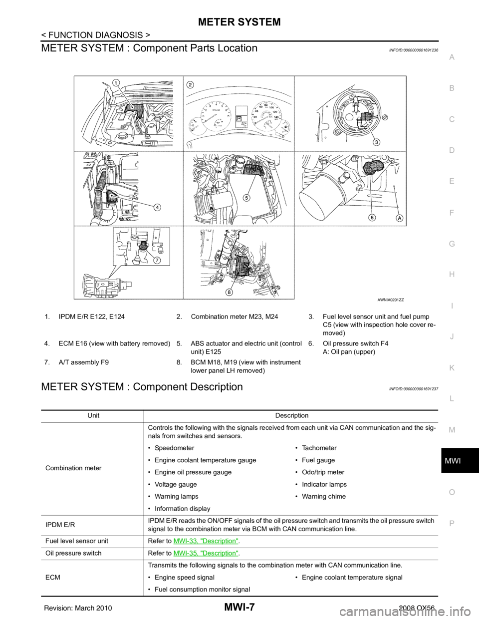
METER SYSTEM : Com ponent Parts LocationINFOID:0000000001691236
METER SYSTEM : Component DescriptionINFOID:0000000001691237
1. IPDM E/R E122, E124 2. Combination meter M23, M24 3. Fuel level sensor unit and fuel pump
C5 (view with inspection hole cover re-
moved)
4. ECM E16 (view with battery removed) 5. ABS actuator and electric unit (control unit) E1256. Oil pressure switch F4
A: Oil pan (upper)
7. A/T assembly F9 8. BCM M18, M19 (view with instrument
lower panel LH removed)
AWNIA0201ZZ
Unit Description
Combination meter Controls the following with the signals received from each unit via CAN communication and the sig-
nals from switches and sensors.
• Speedometer
• Tachometer
• Engine coolant temperature gauge • Fuel gauge
• Engine oil pressure gauge • Odo/trip meter
• Voltage gauge • Indicator lamps
• Warning lamps • Warning chime
• Information display
IPDM E/R IPDM E/R reads the ON/OFF signals of the oil pressure switch and transmits the oil pressure switch
signal to the combination meter via BCM with CAN communication line.
Fuel level sensor unit Refer to MWI-33, "
Description".
Oil pressure switch Refer to MWI-35, "
Description".
ECM Transmits the following signals to the combination meter with CAN communication line.
• Engine speed signal
• Engine coolant temperature signal
• Fuel consumption monitor signal
Revision: March 2010 2008 QX56