2008 INFINITI QX56 check transmission fluid
[x] Cancel search: check transmission fluidPage 1044 of 4083
![INFINITI QX56 2008 Factory Service Manual DLN-14
< FUNCTION DIAGNOSIS >[ATX14B]
4WD SYSTEM
• Displays 4LO condition while engine is running. 4LO indicator lamp flashes if transfer gear does not shift
completely under 2WD, AUTO, 4H ⇔4LO. ( INFINITI QX56 2008 Factory Service Manual DLN-14
< FUNCTION DIAGNOSIS >[ATX14B]
4WD SYSTEM
• Displays 4LO condition while engine is running. 4LO indicator lamp flashes if transfer gear does not shift
completely under 2WD, AUTO, 4H ⇔4LO. (](/manual-img/42/57030/w960_57030-1043.png)
DLN-14
< FUNCTION DIAGNOSIS >[ATX14B]
4WD SYSTEM
• Displays 4LO condition while engine is running. 4LO indicator lamp flashes if transfer gear does not shift
completely under 2WD, AUTO, 4H ⇔4LO. (When 4WD warning lamp is turned on, 4LO indicator lamp is
turned off.)
• Turns ON for approximately 1 second when ignition switch is turned ON, for purpose of lamp check.
4WD WARNING LAMP
Turns on or flashes when there is a malfunction in 4WD system.
Also turns on when ignition switch is turned ON, for purpose of lamp che\
ck. Turns OFF approximately 1 sec-
ond after the engine starts if system is normal.
4WD Warning Lamp Indication
ATP WARNING LAMP
When the A/T selector lever is in P position, the vehicle may move if the transfer case is in neutral. ATP warn-
ing lamp is turned on to indicate this condition to the driver.
LINE PRESSURE SWITCH
• With the transfer system design, control of the oil pressure provides the transmission of drive torque to the
front wheels. The main pressure to control the oil pressure is referred to as the line pressure.
• The line pressure switch determines whether or not adequate line pressure has built up under different oper- ating conditions.
• The line pressure switch closes when line pressure is produced.
• The line pressure switch senses line pressure abnormalities and turns the 4WD warning lamp ON.
CLUTCH PRESSURE SWITCH
• The clutch pressure switch determines whether or not adequate clutch pressure has built up under different
operating conditions.
• The clutch pressure switch closes when clutch pressure is produced.
• The clutch pressure switch senses clutch pressure abnormalities and turns the 4WD warning lamp ON.
WAIT DETECTION SWITCH
• The wait detection switch operates when there is circulating torque produced in the propeller shaft (L→H) or
when there is a phase difference between 2-4 sleeve and clutch drum (H →L). After the release of the circu-
lating torque, the wait detection switch helps provi de the 4WD lock gear (clutch drum) shifts. A difference
may occur between the operation of the 4WD shift swit ch and actual drive mode. At this point, the wait
detection switch senses an actual drive mode.
• The wait detection switch operates as follows.
- 4WD lock gear (clutch drum) locked: ON
- 4WD lock gear (clutch drum) released: OFF
• The wait detection switch senses an actual drive mode and the 4WD shift indicator lamp indicates the vehi-
cle drive mode.
ATP SWITCH
ATP switch detects if transfer case is in neutral by the position of the L-H shift fork.
NOTE:
Transfer case may be in neutral when shifting between 4H-4LO.
NEUTRAL-4LO SWITCH
The neutral-4LO switch detects that transfer gear is in neutral or 4LO (or shifting from neutral to 4LO) condi-
tion by L-H shift fork position.
Condition 4WD warning lamp
System normal OFF
Lamp check Turns ON when ignition switch is turned ON.
Turns OFF after engine start.
4WD system malfunction ON
During self-diagnosis Flashes malfunction mode.
Large difference in diameter of front/
rear tires Flashes slow (1 flash / 2 seconds)
(Continues to flash until the ignition switch is turned OFF)
High fluid temperature in transfer case Flashes rapidly (2 flashes / 1 second)
(Continues to flash until fluid temperature returns to normal)
Revision: March 2010 2008 QX56
Page 1127 of 4083
![INFINITI QX56 2008 Factory Service Manual TRANSFER CONTROL UNITDLN-97
< ECU DIAGNOSIS > [ATX14B]
C
EF
G H
I
J
K L
M A
B
DLN
N
O P
CAUTION:
• If CAN COMM CIRCUIT [U1000] or CONTROL UNIT (CAN) [U1010] is displayed with other DTCs, first perf INFINITI QX56 2008 Factory Service Manual TRANSFER CONTROL UNITDLN-97
< ECU DIAGNOSIS > [ATX14B]
C
EF
G H
I
J
K L
M A
B
DLN
N
O P
CAUTION:
• If CAN COMM CIRCUIT [U1000] or CONTROL UNIT (CAN) [U1010] is displayed with other DTCs, first perf](/manual-img/42/57030/w960_57030-1126.png)
TRANSFER CONTROL UNITDLN-97
< ECU DIAGNOSIS > [ATX14B]
C
EF
G H
I
J
K L
M A
B
DLN
N
O P
CAUTION:
• If CAN COMM CIRCUIT [U1000] or CONTROL UNIT (CAN) [U1010] is displayed with other DTCs, first perform the trouble
diagnosis for CAN communication line.
• If ABS OP SIG [P1830], VDC OP SIG [P1831] or TCS OP SIG [P 1832] is displayed, first perform the trouble diagnosis for ABS
system.
• If VHCL SPEED SEN·AT [P1807] is displayed, firs t perform the trouble diagnosis for A/T system.
NOTE:
• If SHIFT ACT POSI SW [P1818] or SHIFT ACT CIR [P1819] is disp layed, first erase self-diagnostic results. (SHIFT ACT POSI SW
[P1818] or SHIFT ACT CIR [P1819] may be displayed after installing transfer control unit or transfer assembly.)
• If CL PRES SW [P1827] or LINE PRES SW [P1828] is displayed only while driving in reverse, check the continuity of R position o n
transmission range switch. When there is no malfunction found in the electrical system, check the hydraulic system.
FLASH CODE CHART
[P1826] OIL TEMP SEN Signal voltage from transfer fluid temperature sen-
sor is abnormally high (Transfer fluid temperature is
abnormally low) while driving. Refer to
DLN-67.
[P1827] CLUTCH PRES SW • Improper signal from clutch pressure switch is in-
put due to open or short circuit.
• Malfunction occurs in clutch pressure switch or
hydraulic circuit. Refer to
DLN-70
.
[P1828] LINE PRES SW • Improper signal from line pressure switch is input
due to open or short circuit.
• Malfunction occurs in line pressure switch or hy-
draulic circuit. Refer to
DLN-73
.
[P1829] THROTTLE POSI SEN • Malfunction is detected in accelerator pedal posi-
tion signal that is output from ECM through CAN
communication.
• Signal voltage from accelerator pedal position sensor is abnormally high or low. Refer to
DLN-76
.
[P1830] ABS OP SIG Malfunction is detected in ABS operation signal that
is output from ABS actuator and electric unit (control
unit) through CAN communication. Refer to
DLN-77
.
[P1831] VDC OP SIG Malfunction is detected in VDC operation signal that
is output from ABS actuator and electric unit (control
unit) through CAN communication.
Refer to
DLN-78
.
[P1832] TCS OP SIG Malfunction is detected in TCS operation signal that
is output from ABS actuator and electric unit (control
unit) through CAN communication. Refer to
DLN-79
.
DTC CONSULT-III Diagnostic item is detected when... Reference
Flashing pattern
ItemDiagnostic item is detected when... Reference
2 Vehicle speed signal
(from A/T) • Malfunction is detected in output speed sensor signal that
is output from TCM through CAN communication.
• Improper signal is input while driving. Refer to DLN-26
.
3 Clutch pressure sole-
noid signal Proper voltage is not applied to clutch pressure solenoid
valve due to open or short circuit.
Refer to DLN-53
.
4 2-4WD solenoid signal Proper voltage is not applied to 2-4WD solenoid valve due
to open or short circuit. Refer to DLN-57
.
5 Transfer motor Transfer motor does not operate properly due to open or
short circuit in transfer motor or transfer motor relay.
Refer to DLN-61
.
6 Vehicle speed signal
(from ABS) • Malfunction is detected in vehicle speed signal that is out-
put from ABS actuator and electric unit (control unit)
through CAN communication.
• Improper signal is input while driving. Refer to DLN-27
.
7 CAN communication Malfunction has been detected from CAN communication
line. Refer to LAN-51
.
8 AD converter AD converter system of transfer control unit is malfunction-
ing. Refer to DLN-24
.
Revision: March 2010
2008 QX56
Page 1855 of 4083
EM-52
< ON-VEHICLE REPAIR >
TIMING CHAIN
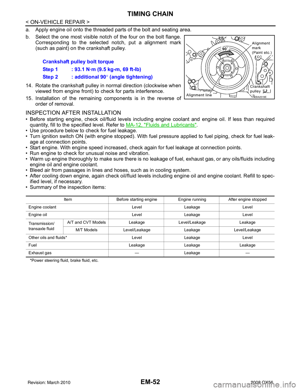
a. Apply engine oil onto the threaded parts of the bolt and seating area.
b. Select the one most visible notch of the four on the bolt flange.Corresponding to the selected notch, put a alignment mark
(such as paint) on the crankshaft pulley.
14. Rotate the crankshaft pulley in normal direction (clockwise when viewed from engine front) to check for parts interference.
15. Installation of the remaining components is in the reverse of order of removal.
INSPECTION AFTER INSTALLATION
• Before starting engine, check oil/fluid levels incl uding engine coolant and engine oil. If less than required
quantity, fill to the specified level. Refer to MA-12, "
Fluids and Lubricants".
• Use procedure below to check for fuel leakage.
• Turn ignition switch ON (with engine stopped). With fuel pressure applied to fuel piping, check for fuel leak- age at connection points.
• Start engine. With engine speed increased, che ck again for fuel leakage at connection points.
• Run engine to check for unusual noise and vibration.
• Warm up engine thoroughly to make sure there is no leakage of fuel, exhaust gas, or any oils/fluids including
engine oil and engine coolant.
• Bleed air from passages in lines and hoses, such as in cooling system.
• After cooling down engine, again check oil/fluid levels including engine oil and engine coolant. Refill to spec-
ified level, if necessary.
• Summary of the inspection items:
*Power steering fluid, brake fluid, etc.
Crankshaft pulley bolt torque
Step 1 : 93.1 N·m (9.5 kg-m, 69 ft-lb)
Step 2 : additional 90 ° (angle tightening)
KBIA2519E
Item Before starting engine Engine runningAfter engine stopped
Engine coolant LevelLeakage Level
Engine oil LevelLeakage Level
Transmission/
transaxle fluid A/T and CVT Models
LeakageLevel/Leakage Leakage
M/T Models Level/Leakage LeakageLevel/Leakage
Other oils and fluids* LevelLeakage Level
Fuel LeakageLeakage Leakage
Exhaust gas —Leakage —
Revision: March 2010 2008 QX56
Page 1881 of 4083
EM-78
< REMOVAL AND INSTALLATION >
ENGINE ASSEMBLY
REMOVAL AND INSTALLATION
ENGINE ASSEMBLY
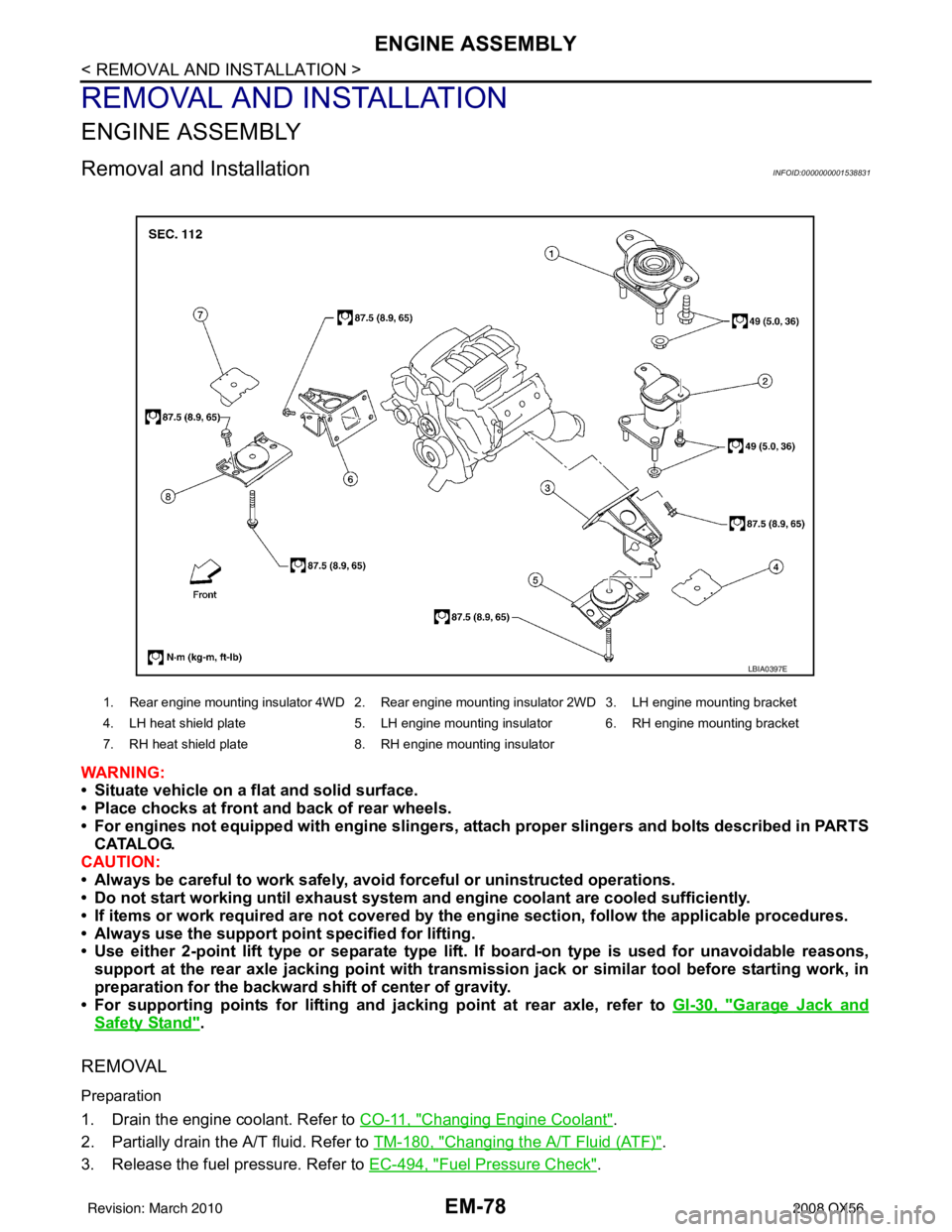
Removal and InstallationINFOID:0000000001538831
WARNING:
• Situate vehicle on a flat and solid surface.
• Place chocks at front and back of rear wheels.
• For engines not equipped with engine slingers, attach proper slingers and bolts described in PARTS
CATALOG.
CAUTION:
• Always be careful to work safely, avoid forceful or uninstructed operations.
• Do not start working until exh aust system and engine coolant are cooled sufficiently.
• If items or work required are no t covered by the engine section, follow the applicable procedures.
• Always use the support poin t specified for lifting.
• Use either 2-point lift type or separate type lift. If board-on type is used for unavoidable reasons,
support at the rear axle jacking point with transmission jack or similar tool before starting work, in
preparation for the backward shift of center of gravity.
• For supporting points for lifting and jacking point at rear axle, refer to GI-30, "
Garage Jack and
Safety Stand".
REMOVAL
Preparation
1. Drain the engine coolant. Refer to CO-11, "Changing Engine Coolant".
2. Partially drain the A/T fluid. Refer to TM-180, "
Changing the A/T Fluid (ATF)".
3. Release the fuel pressure. Refer to EC-494, "
Fuel Pressure Check".
1. Rear engine mounting insulator 4WD 2. Rear engine mounting insulator 2WD 3. LH engine mounting bracket
4. LH heat shield plate 5. LH engine mounting insulator 6. RH engine mounting bracket
7. RH heat shield plate 8. RH engine mounting insulator
LBIA0397E
Revision: March 2010 2008 QX56
Page 1883 of 4083
EM-80
< REMOVAL AND INSTALLATION >
ENGINE ASSEMBLY
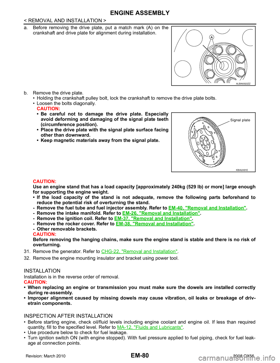
a. Before removing the drive plate, put a match mark (A) on thecrankshaft and drive plate for alignment during installation.
b. Remove the drive plate. • Holding the crankshaft pulley bolt, lock the crankshaft to remove the drive plate bolts.
• Loosen the bolts diagonally.
CAUTION:
• Be careful not to damage the drive plate. Especiallyavoid deforming and damaging of the signal plate teeth
(circumference position).
• Place the drive plate with th e signal plate surface facing
other than downward.
• Keep magnetic materials away from the signal plate.
CAUTION:
Use an engine stand that has a load capacity [a pproximately 240kg (529 lb) or more] large enough
for supporting the engine weight.
• If the load capacity of the stand is not adeq uate, remove the following parts beforehand to
reduce the potential risk of overturning the stand.
- Remove the fuel tube and fuel injector assembly. Refer to EM-40, "
Removal and Installation".
- Remove the intake manifold. Refer to EM-26, "
Removal and Installation".
- Remove the ignition coil. Refer to EM-37, "
Removal and Installation".
- Remove the rocker cover. Refer to EM-38, "
Removal and Installation".
- Other removable brackets.
CAUTION:
Before removing the hanging chains, make sure th e engine stand is stable and there is no risk of
overturning.
31. Remove the generator. Refer to CHG-22, "
Removal and Installation".
32. Remove the engine mounting insulator and bracket using power tool.
INSTALLATION
Installation is in the reverse order of removal.
CAUTION:
• When replacing an engine or transmission you mu st make sure the dowels are installed correctly
during re-assembly.
• Improper alignment caused by mi ssing dowels may cause vibration, oil leaks or breakage of driv-
etrain components.
INSPECTION AFTER INSTALLATION
• Before starting engine, check oil/fluid levels incl uding engine coolant and engine oil. If less than required
quantity, fill to the specified level. Refer to MA-12, "
Fluids and Lubricants".
• Use procedure below to check for fuel leakage.
• Turn ignition switch ON (with engine stopped). With fuel pressure applied to fuel piping, check for fuel leak- age at connection points.
ALBIA0522ZZ
KBIA2491E
Revision: March 2010 2008 QX56
Page 1884 of 4083
ENGINE ASSEMBLYEM-81
< REMOVAL AND INSTALLATION >
C
DE
F
G H
I
J
K L
M A
EM
NP
O
• Start engine. With engine speed increased, check again for fuel leakage at connection points.
• Run engine to check for unusual noise and vibration.
• Warm up engine thoroughly to make sure there is no leak
age of fuel, exhaust gas, or any oils/fluids including
engine oil and engine coolant.
• Bleed air from passages in lines and hoses, such as in cooling system.
• After cooling down engine, again check oil/fluid levels including engine oil and engine coolant. Refill to spec- ified level, if necessary.
• Summary of the inspection items:
*Power steering fluid, brake fluid, etc. Item
Before starting engine Engine runningAfter engine stopped
Engine coolant LevelLeakage Level
Engine oil LevelLeakage Level
Transmission/
transaxle fluid A/T and CVT Models
LeakageLevel/Leakage Leakage
M/T Models Level/Leakage LeakageLevel/Leakage
Other oils and fluids* LevelLeakage Level
Fuel LeakageLeakageLeakage
Exhaust gas —Leakage —
Revision: March 2010 2008 QX56
Page 2168 of 4083
GI-26
< PRECAUTION >
PRECAUTIONS
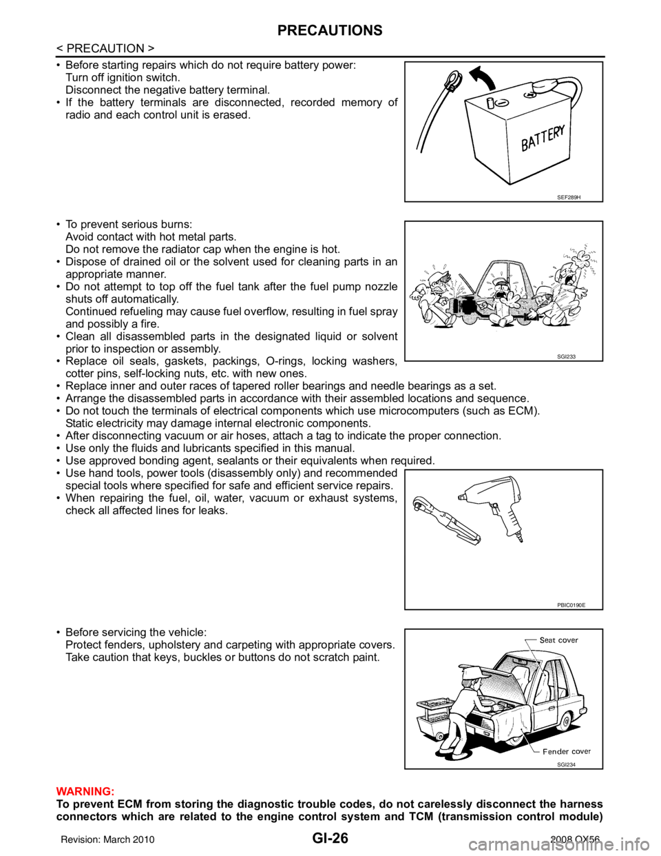
• Before starting repairs which do not require battery power:Turn off ignition switch.
Disconnect the negative battery terminal.
• If the battery terminals are disconnected, recorded memory of radio and each control unit is erased.
• To prevent serious burns: Avoid contact with hot metal parts.
Do not remove the radiator cap when the engine is hot.
• Dispose of drained oil or the solvent used for cleaning parts in an appropriate manner.
• Do not attempt to top off the fuel tank after the fuel pump nozzle
shuts off automatically.
Continued refueling may cause fuel overflow, resulting in fuel spray
and possibly a fire.
• Clean all disassembled parts in the designated liquid or solvent prior to inspection or assembly.
• Replace oil seals, gaskets, packings, O-rings, locking washers,
cotter pins, self-locking nuts, etc. with new ones.
• Replace inner and outer races of tapered roller bearings and needle bearings as a set.
• Arrange the disassembled parts in accordance with their assembled locations and sequence.
• Do not touch the terminals of electrical com ponents which use microcomputers (such as ECM).
Static electricity may damage internal electronic components.
• After disconnecting vacuum or air hoses, atta ch a tag to indicate the proper connection.
• Use only the fluids and lubricants specified in this manual.
• Use approved bonding agent, sealants or their equivalents when required.
• Use hand tools, power tools (disassembly only) and recommended special tools where specified for safe and efficient service repairs.
• When repairing the fuel, oil, water, vacuum or exhaust systems, check all affected lines for leaks.
• Before servicing the vehicle: Protect fenders, upholstery and carpeting with appropriate covers.
Take caution that keys, buckles or buttons do not scratch paint.
WARNING:
To prevent ECM from storing the diagnostic tro uble codes, do not carelessly disconnect the harness
connectors which are related to the engine control system and TCM (transmission control module)
SEF289H
SGI233
PBIC0190E
SGI234
Revision: March 2010 2008 QX56
Page 2599 of 4083
MA-1
MAINTENANCE
C
DE
F
G H
I
J
K L
M B
MA
SECTION MA
N
O A
CONTENTS
MAINTENANCE
PREPARATION ....
........................................2
PRECAUTIONS .............................................. .....2
Precaution for Supplemental Restraint System
(SRS) "AIR BAG" and "SEAT BELT PRE-TEN-
SIONER" ............................................................. ......
2
Precaution Necessary for Steering Wheel Rota-
tion After Battery Disconnect ............................... ......
2
PREPARATION ...................................................4
Special Service Tool ........................................... ......4
Commercial Service Tool ..........................................4
ON-VEHICLE MAINTENANCE .....................6
GENERAL MAINTE NANCE ........................... .....6
General Maintenance .......................................... ......6
PERIODIC MAINTENANCE ................................8
Introduction of Periodic Maintenance .................. ......8
Maintenance for Off-road Driving (4WD only) ...........8
Schedule 1 ................................................................8
Schedule 2 ..............................................................10
RECOMMENDED FLUIDS AND LUBRI-
CANTS ................................................................
12
Fluids and Lubricants .......................................... ....12
Engine Oil Recommendation ..................................12
Anti-Freeze Coolant Mixture Ratio ..........................13
ENGINE MAINTENANCE ...................................14
Checking Drive Belts ........................................... ....14
Changing Engine Coolant .................................... ....14
Checking Fuel Line ..................................................17
Changing Fuel Filter ................................................17
Changing Engine Air Cleaner Filter .........................17
Changing Engine Oil ................................................18
Changing Oil Filter ...................................................18
Changing Spark Plugs .............................................20
Checking EVAP Vapor Line .....................................21
CHASSIS AND BODY MAINTENANCE ...........22
Changing In-cabin Microfilter ............................... ....22
Checking Exhaust System .......................................23
Checking Automatic Transmission Fluid (ATF) .......23
Changing Automatic Transmission Fluid (ATF) .......25
Changing Transfer Fluid ..........................................25
Checking Transfer Fluid ..........................................26
Checking Propeller Shaft .........................................26
Checking Final Drive Oil ..........................................26
Changing Final Drive Oil ..........................................27
Adjustment ...............................................................27
Tire Rotation ............................................................29
Checking Brake Fluid Level and Leaks ...................29
CheckingBrake Line and Cables .............................30
Checking Disc Brake ...............................................30
Checking Steering Gear and Linkage ......................30
Checking Power Steering Fluid and Line ................31
Checking Axle and Suspension Parts .....................31
Lubricating Locks, Hinges and Hood Latches .........33
Checking Seat Belts, Buckles, Retractors, An-
chors and Adjusters ............................................. ....
33
Revision: March 2010 2008 QX56