Page 1901 of 4083

EM-98
< DISASSEMBLY AND ASSEMBLY >
ENGINE UNIT
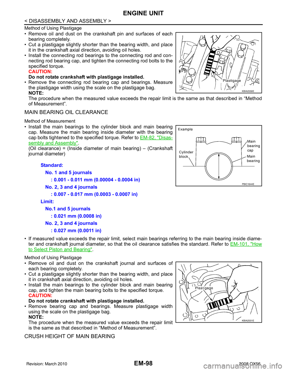
Method of Using Plastigage
• Remove oil and dust on the crankshaft pin and surfaces of eachbearing completely.
• Cut a plastigage slightly shorter than the bearing width, and place
it in the crankshaft axial direction, avoiding oil holes.
• Install the connecting rod beari ngs to the connecting rod and con-
necting rod bearing cap, and tighten the connecting rod bolts to the
specified torque.
CAUTION:
Do not rotate crankshaft with plastigage installed.
• Remove the connecting rod bear ing cap and bearings. Measure
the plastigage width using the scale on the plastigage bag.
NOTE:
The procedure when the measured value exceeds the repair limit is the same as that described in “Method
of Measurement”.
MAIN BEARING OIL CLEARANCE
Method of Measurement
• Install the main bearings to the cylinder block and main bearing cap. Measure the main bearing inside diameter with the bearing
cap bolts tightened to the specified torque. Refer to EM-82, "
Disas-
sembly and Assembly".
(Oil clearance) = (Inside diameter of main bearing) – (Crankshaft
journal diameter)
• If measured value exceeds the repair limit, select main bearings referring to the main bearing inside diame-
ter and crankshaft journal diameter, so that the oil clearance satisfies the standard. Refer to EM-101, "
How
to Select Piston and Bearing".
Method of Using Plastigage
• Remove oil and dust on the crankshaft journal and surfaces of
each bearing completely.
• Cut a plastigage slightly shorter than the bearing width, and place it in crankshaft axial direction, avoiding oil holes.
• Install the main bearings to the cylinder block and main bearing cap, and tighten the main bearing bolts to the specified torque.
CAUTION:
Do not rotate crankshaft with plastigage installed.
• Remove bearing cap and bearings. Measure plastigage width using the scale on the plastigage bag.
NOTE:
The procedure when the measured value exceeds the repair limit
is the same as that descri bed in “Method of Measurement”.
CRUSH HEIGHT OF MAIN BEARING
KBIA2550E
Standard:
No. 1 and 5 journals : 0.001 - 0.011 mm (0.00004 - 0.0004 in)
No. 2, 3 and 4 journals : 0.007 - 0.017 mm (0.0003 - 0.0007 in)
Limit: No.1 and 5 journals : 0.021 mm (0.0008 in)
No. 2, 3 and 4 journals : 0.027 mm (0.0011 in)
PBIC1644E
KBIA2551E
Revision: March 2010 2008 QX56
Page 1902 of 4083

ENGINE UNITEM-99
< DISASSEMBLY AND ASSEMBLY >
C
DE
F
G H
I
J
K L
M A
EM
NP
O
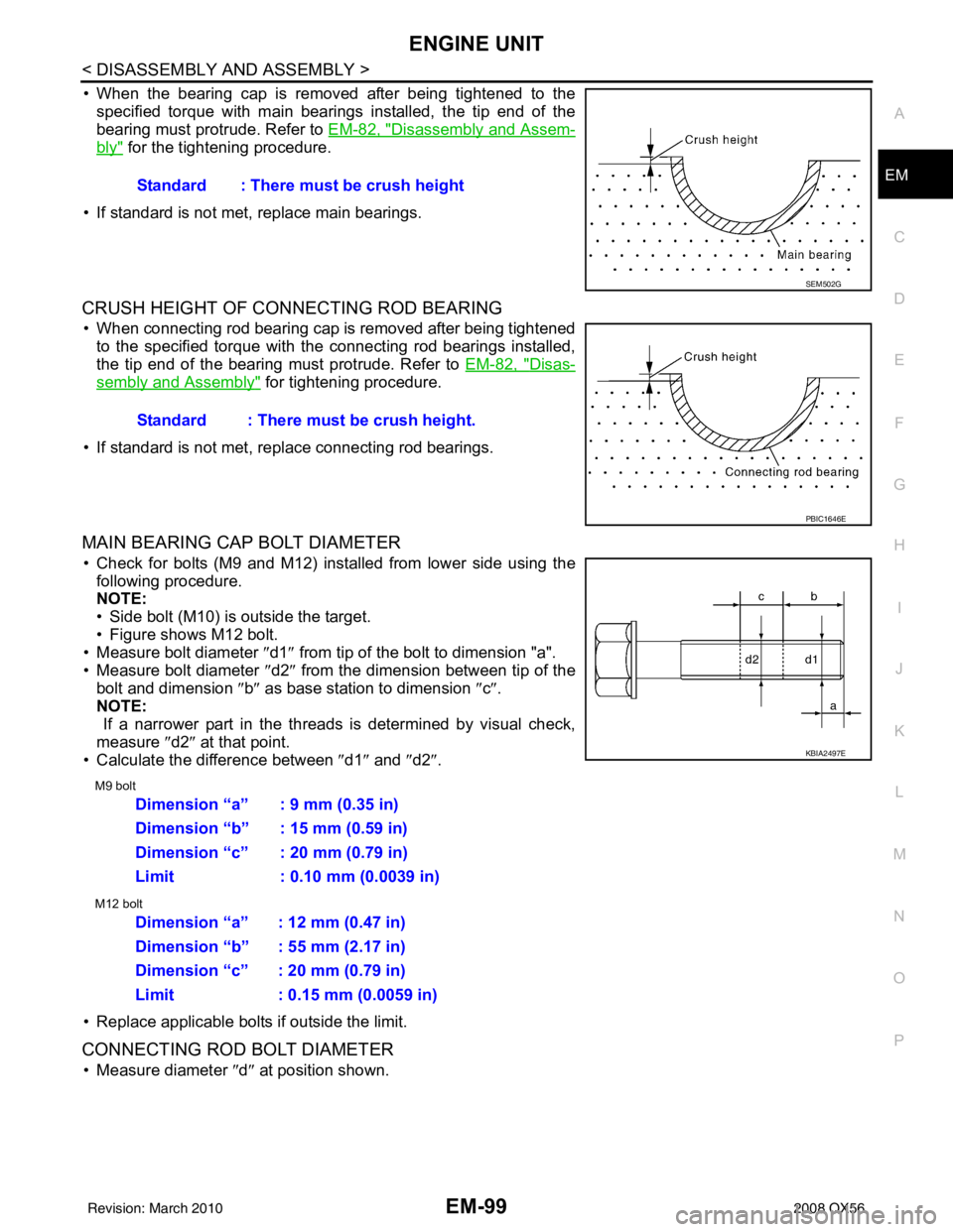
• When the bearing cap is removed after being tightened to the
specified torque with main bearings installed, the tip end of the
bearing must protrude. Refer to EM-82, "
Disassembly and Assem-
bly" for the tightening procedure.
• If standard is not met, replace main bearings.
CRUSH HEIGHT OF CONNECTING ROD BEARING
• When connecting rod bearing cap is removed after being tightened to the specified torque with the connecting rod bearings installed,
the tip end of the bearing must protrude. Refer to EM-82, "
Disas-
sembly and Assembly" for tightening procedure.
• If standard is not met, replace connecting rod bearings.
MAIN BEARING CAP BOLT DIAMETER
• Check for bolts (M9 and M12) installed from lower side using the following procedure.
NOTE:
• Side bolt (M10) is outside the target.
• Figure shows M12 bolt.
• Measure bolt diameter ″ d1″ from tip of the bolt to dimension "a".
• Measure bolt diameter ″d2″ from the dimension between tip of the
bolt and dimension ″b ″ as base station to dimension ″c″ .
NOTE:
If a narrower part in the threads is determined by visual check,
measure ″d2″ at that point.
• Calculate the difference between ″d1″ and ″d2″ .
M9 bolt
M12 bolt
• Replace applicable bolts if outside the limit.
CONNECTING ROD BOLT DIAMETER
• Measure diameter ″d ″ at position shown.
Standard : There must be crush height
SEM502G
Standard : There must be crush height.
PBIC1646E
KBIA2497E
Dimension “a” : 9 mm (0.35 in)
Dimension “b” : 15 mm (0.59 in)
Dimension “c” : 20 mm (0.79 in)
Limit : 0.10 mm (0.0039 in)
Dimension “a” : 12 mm (0.47 in)
Dimension “b” : 55 mm (2.17 in)
Dimension “c” : 20 mm (0.79 in)
Limit : 0.15 mm (0.0059 in)
Revision: March 2010
2008 QX56
Page 1912 of 4083

SERVICE DATA AND SPECIFICATIONS (SDS)EM-109
< SERVICE DATA AND SPECIFICATIONS (SDS)
C
DE
F
G H
I
J
K L
M A
EM
NP
O
Unit: mm (in)
SPARK PLUG
Unit: mm (in)
*: Always check with the Parts Department for the latest parts information.
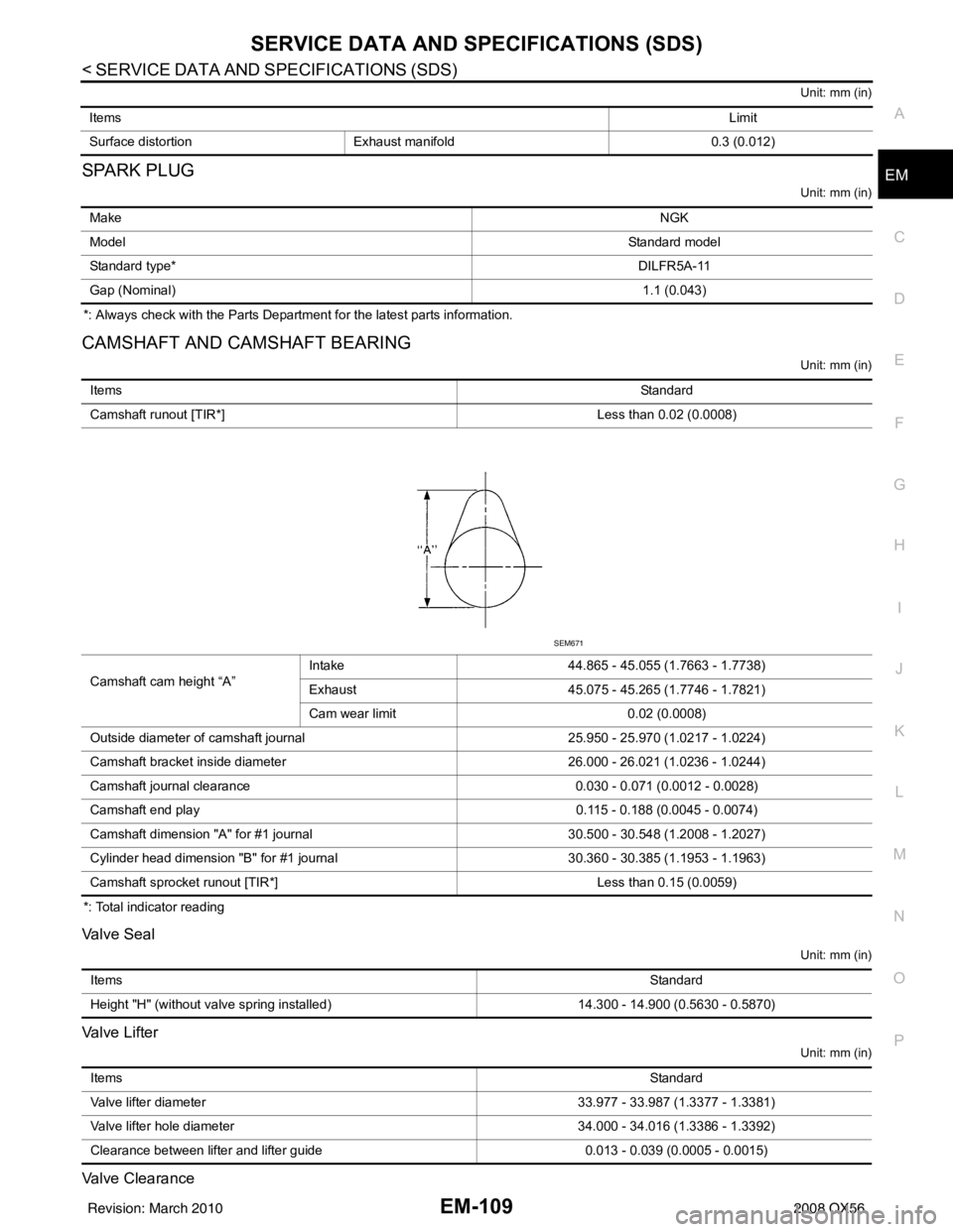
CAMSHAFT AND CAMSHAFT BEARING
Unit: mm (in)
*: Total indicator reading
Valve Seal
Unit: mm (in)
Valve Lifter
Unit: mm (in)
Valve Clearance
Items
Limit
Surface distortion Exhaust manifold 0.3 (0.012)
Make NGK
Model Standard model
Standard type* DILFR5A-11
Gap (Nominal) 1.1 (0.043)
ItemsStandard
Camshaft runout [TIR*] Less than 0.02 (0.0008)
Camshaft cam height “A” Intake
44.865 - 45.055 (1.7663 - 1.7738)
Exhaust 45.075 - 45.265 (1.7746 - 1.7821)
Cam wear limit 0.02 (0.0008)
Outside diameter of camshaft journal 25.950 - 25.970 (1.0217 - 1.0224)
Camshaft bracket inside diameter 26.000 - 26.021 (1.0236 - 1.0244)
Camshaft journal clearance 0.030 - 0.071 (0.0012 - 0.0028)
Camshaft end play 0.115 - 0.188 (0.0045 - 0.0074)
Camshaft dimension "A" for #1 journal 30.500 - 30.548 (1.2008 - 1.2027)
Cylinder head dimension "B" for #1 journal 30.360 - 30.385 (1.1953 - 1.1963)
Camshaft sprocket runout [TIR*] Less than 0.15 (0.0059)
SEM671
Items Standard
Height "H" (without valve spring installed) 14.300 - 14.900 (0.5630 - 0.5870)
Items Standard
Valve lifter diameter 33.977 - 33.987 (1.3377 - 1.3381)
Valve lifter hole diameter 34.000 - 34.016 (1.3386 - 1.3392)
Clearance between lifter and lifter guide 0.013 - 0.039 (0.0005 - 0.0015)
Revision: March 2010 2008 QX56
Page 1914 of 4083
SERVICE DATA AND SPECIFICATIONS (SDS)EM-111
< SERVICE DATA AND SPECIFICATIONS (SDS)
C
DE
F
G H
I
J
K L
M A
EM
NP
O
Unit: mm (in)
Spark Plug Tube
Unit: mm (in)
Valve Dimensions
Unit: mm (in)
Valve Guide
Items
StandardLimit
Head surface distortion 0.03 (0.0012)0.1 (0.004)
Nominal cylinder head height “H” 126.3 (4.97)
KBIA2554E
Items Standard
Press fit height "H" 38.400 - 39.400 (1.512 - 1.551)
Standard model
Valve head diameter “D” Intake
37.0 - 37.3 (1.457 - 1.469)
Exhaust 31.2 - 31.5 (1.228 - 1.240)
Valve length “L” Intake
96.21- 96.71 (3.7878 - 3.8075)
Exhaust 93.74 - 94.24 (3.6905 - 3.7102)
Valve stem diameter “d” Intake
5.965 - 5.980 (0.2348 - 0.2354)
Exhaust 5.955 - 5.970 (0.2344 - 0.2350)
Valve seat angle “ α” Intake
45°15 ′ - 45 °45 ′
Exhaust
Valve margin “T” Intake
1.1 (0.043)
Exhaust 1.3 (0.051)
SEM188
Revision: March 2010 2008 QX56
Page 1915 of 4083
![INFINITI QX56 2008 Factory Service Manual EM-112
< SERVICE DATA AND SPECIFICATIONS (SDS)
SERVICE DATA AND SPECIFICATIONS (SDS)
Unit: mm (in)
Va l v e S e a t
Unit: mm (in)
Valve Spring
CYLINDER BLOCK
ItemsStandardOversize [0.2 (0.008)] (ser INFINITI QX56 2008 Factory Service Manual EM-112
< SERVICE DATA AND SPECIFICATIONS (SDS)
SERVICE DATA AND SPECIFICATIONS (SDS)
Unit: mm (in)
Va l v e S e a t
Unit: mm (in)
Valve Spring
CYLINDER BLOCK
ItemsStandardOversize [0.2 (0.008)] (ser](/manual-img/42/57030/w960_57030-1914.png)
EM-112
< SERVICE DATA AND SPECIFICATIONS (SDS)
SERVICE DATA AND SPECIFICATIONS (SDS)
Unit: mm (in)
Va l v e S e a t
Unit: mm (in)
Valve Spring
CYLINDER BLOCK
ItemsStandardOversize [0.2 (0.008)] (service)
Va l v e g u i d e Outside diameter
10.023 - 10.034 (0.3946 - 0.3950) 10.223 - 10.234 (0.4025 - 0.4029)
Inside diameter (Finished size) 6.000 - 6.018 (0.2362 - 0.2369) —
Cylinder head valve guide hole diameter 9.975 - 9.996 (0.3927 - 0.3935) 10.175 - 10.196 (0.4006 - 0.4014)
Interference fit of valve guide 0.027 - 0.059 (0.0011 - 0.0023)
Items StandardLimit
Stem to guide clearance Intake
0.020 - 0.053 (0.0008 - 0.0021) 0.08 (0.0031)
Exhaust 0.030 - 0.063 (0.0012 - 0.0025) 0.09 (0.0035)
Projection length “L” Intake
12.6 - 12.8 (0.496 - 0.504)
Exhaust 12.5 - 12.9 (0.492 - 0.508)
KBIA2555E
Items StandardOversize [0.5 (0.020)] (Service)
Cylinder head seat recess diameter (D) Intake 38.000 - 38.016 (1.4961 - 1.4967) 38.500 - 38.516 (1.5157 - 1.5164)
Exhaust 32.200 - 32.216 (1.2677 - 1.2683) 32.700 - 32.716 (1.2874 - 1.2880)
Valve seat interference fit Intake
0.081 - 0.113 (0.0032 - 0.0044)
Exhaust 0.064 - 0.096 (0.0025 - 0.0038)
Valve seat diameter (d) Intake 38.097 - 38.113 (1.4999 - 1.5005) 38.597 - 38.613 (1.5196 - 1.5202)
Exhaust 32.280 - 32.296 (1.2709 - 1.2715) 32.780 - 32.796 (1.2905 - 1.2912)
KBIA2541E
Free height mm (in)
50.58 (1.9913)
Pressure N (kg, lb) at height mm (in) Installation
165.8 - 187.0 (16.9 - 19.1, 37 - 42) at 37.0 (1.457)
Valve open 314.8 - 355.0 (32.1 - 36.2, 71 - 80) at 28.2 (1.110)
Out-of-square mm (in) Less than 2.2 (0.087)
Revision: March 2010 2008 QX56
Page 1928 of 4083

EXHAUST SYSTEMEX-7
< ON-VEHICLE REPAIR >
C
DE
F
G H
I
J
K L
M A
EX
NP
O• Discard any heated oxygen sensor which has been dr
opped from a height of more than 0.5 m (19.7
in) onto a hard surface such as a co ncrete floor; replace with a new one.
• Do not over-torque the heated oxygen sensor. Doing so may damage the heated oxygen sensor,
resulting in the MIL coming on.
• If any mounting insulator is badly deformed, repair or replace it. If deposits such as mud pile up on
the mounting insulators, clean and inspect them.
• Temporarily tighten the nuts on the exhaust manifold side and th e bolts on the vehicle side. Check
each part for interference with other components, an d then tighten the nuts and bolts to specifica-
tion.
INSPECTION AFTER INSTALLATION
• With the engine running, check exhaust tube joints for gas leakage and unusual noises.
• Check to ensure that mounting brackets and mount ing rubbers are installed properly and free from undue
stress. Improper installation could resu lt in excessive noise and vibration.
Tool number A: — (J-43897-18)
B: — (J-43897-12)
Revision: March 2010 2008 QX56
Page 1942 of 4083
EXL-14
< FUNCTION DIAGNOSIS >
HEADLAMP AIMING SYSTEM (MANUAL)
HEADLAMP AIMING SYSTEM (MANUAL)
System DiagramINFOID:0000000001806201
System DescriptionINFOID:0000000001806202
The headlamp aiming system (manual) controls the headlamp light axis height according to input from the
headlamp aiming switch. The variable internal resist ance of the headlamp aiming switch controls the signal
ground of the headlamp aiming motors located on the front combination lamp LH and RH.
Component DescriptionINFOID:0000000001806204
AWLIA1629GB
Part Description
Headlamp aiming motor Moves the headlamp up/down based on input from the headlamp aiming switch.
Headlamp aiming switch Controls variable ground to the headlamp aiming motor signal to move the headlamp aim-
ing motor up/down.
Revision: March 2010
2008 QX56
Page 2040 of 4083
EXL-112
< ON-VEHICLE REPAIR >
ADJUSTMENT AND INSPECTION
• See that vehicle is unloaded (except for full levels of coolant,engine oil and fuel, and spare tire, jack, and tools). Have the driver
or equivalent weight placed in driver seat.
Adjust aiming in the vertical direction by turning the adjustment
screw.
NOTE:
Access adjustment screw from underneath front bumper. Turn screw
clockwise to raise pattern and counterclockwise to lower pattern.
1. Set the distance between the screen and the center of the fog lamp lens as shown.
2. Turn front fog lamps ON.
3. Adjust front fog lamps using adjusting screw so that the top edge of the high intensity zone is 200 mm (7.9 in) below the height of
the fog lamp centers as shown.
• When performing adjustment, if necessary, cover the head-lamps and opposite fog lamp.
SEL350X
MEL327G
MEL328GA
Revision: March 2010 2008 QX56