Page 3121 of 4083

SCS-38
< SYMPTOM DIAGNOSIS >
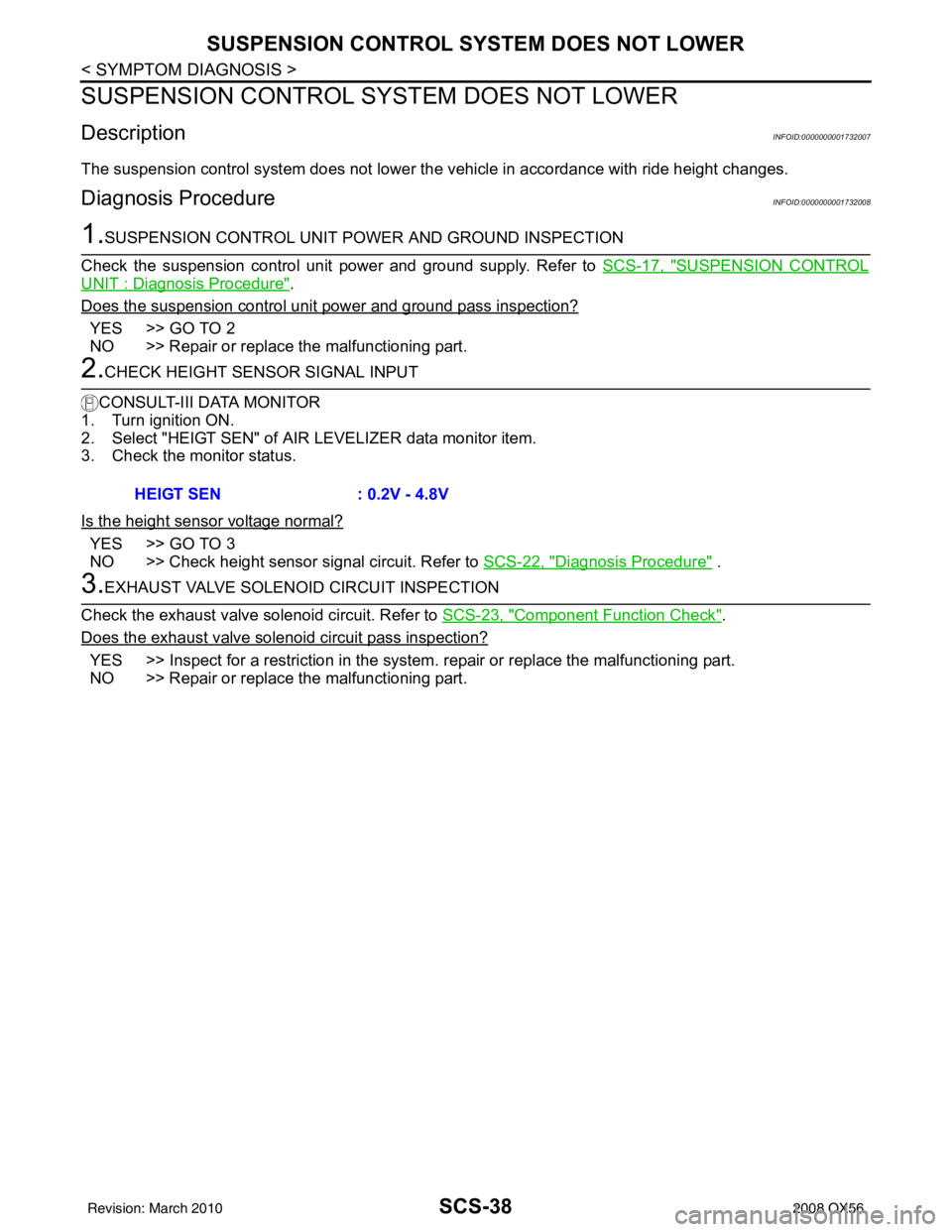
SUSPENSION CONTROL SYSTEM DOES NOT LOWER
SUSPENSION CONTROL SYSTEM DOES NOT LOWER
DescriptionINFOID:0000000001732007
The suspension control system does not lower the vehicle in accordance with ride height changes.
Diagnosis ProcedureINFOID:0000000001732008
1.SUSPENSION CONTROL UNIT PO WER AND GROUND INSPECTION
Check the suspension control unit power and ground supply. Refer to SCS-17, "
SUSPENSION CONTROL
UNIT : Diagnosis Procedure".
Does the suspension control unit power and ground pass inspection?
YES >> GO TO 2
NO >> Repair or replace the malfunctioning part.
2.CHECK HEIGHT SENSOR SIGNAL INPUT
CONSULT-III DATA MONITOR
1. Turn ignition ON.
2. Select "HEIGT SEN" of AI R LEVELIZER data monitor item.
3. Check the monitor status.
Is the height sensor voltage normal?
YES >> GO TO 3
NO >> Check height sensor signal circuit. Refer to SCS-22, "
Diagnosis Procedure" .
3.EXHAUST VALVE SOLENOID CIRCUIT INSPECTION
Check the exhaust valve solenoid circuit. Refer to SCS-23, "
Component Function Check".
Does the exhaust valve solenoid circuit pass inspection?
YES >> Inspect for a restriction in the system . repair or replace the malfunctioning part.
NO >> Repair or replace the malfunctioning part. HEIGT SEN
: 0.2V - 4.8V
Revision: March 2010 2008 QX56
Page 3750 of 4083
CONTROL VALVE WITH TCMTM-203
< ON-VEHICLE REPAIR >
CEF
G H
I
J
K L
M A
B
TM
N
O P
10. Remove bolts (A), (B) and (C) from control valve with TCM.
11. Remove control valve with TCM from transmission case. CAUTION:
When removing, be careful with the manual valve notch and
manual plate height. Remove it vertically.
12. Remove the A/T fluid temperature sensor 2 or plug as shown below.
a. A/T fluid temperature sensor 2
i. Remove A/T fluid temperature sensor 2 with bracket from con- trol valve with TCM.
ii. Remove bracket from A/T fluid temperature sensor 2.
b. Plug
: Front
Bolt symbol Length mm (in) Number of bolts
A 42 (1.65) 5
B 55 (2.17) 6
C 40 (1.57) 1
SCIA8074E
SCIA5142E
SCIA5253E
SCIA5264E
Revision: March 2010 2008 QX56
Page 3786 of 4083
DISASSEMBLYTM-239
< DISASSEMBLY AND ASSEMBLY >
CEF
G H
I
J
K L
M A
B
TM
N
O P
33. Disconnect output speed sensor connector (1). CAUTION:
Do not damage connector.
34. Straighten terminal clip ( ) to free output speed sensor har- ness.
35. Remove bolts (A), (B) and (C) from control valve with TCM. • : Front
36. Remove control valve with TCM from transmission case. CAUTION:
When removing, be careful with the manual valve notch and
manual plate height. Remove it vertically.
37. Remove A/T fluid temperature sensor 2 with bracket from con- trol valve with TCM.
JSDIA1319ZZ
JSDIA1320ZZ
Bolt symbol Length mm (in) Number of bolts
A 42 (1.65) 5
B 55 (2.17) 6
C 40 (1.57) 1
SCIA8077E
SCIA5260E
SCIA5301E
Revision: March 2010 2008 QX56