2008 INFINITI QX56 check engine
[x] Cancel search: check enginePage 3926 of 4083
WCS
COMBINATION METERWCS-49
< ECU DIAGNOSIS >
C
DE
F
G H
I
J
K L
M B A
O P
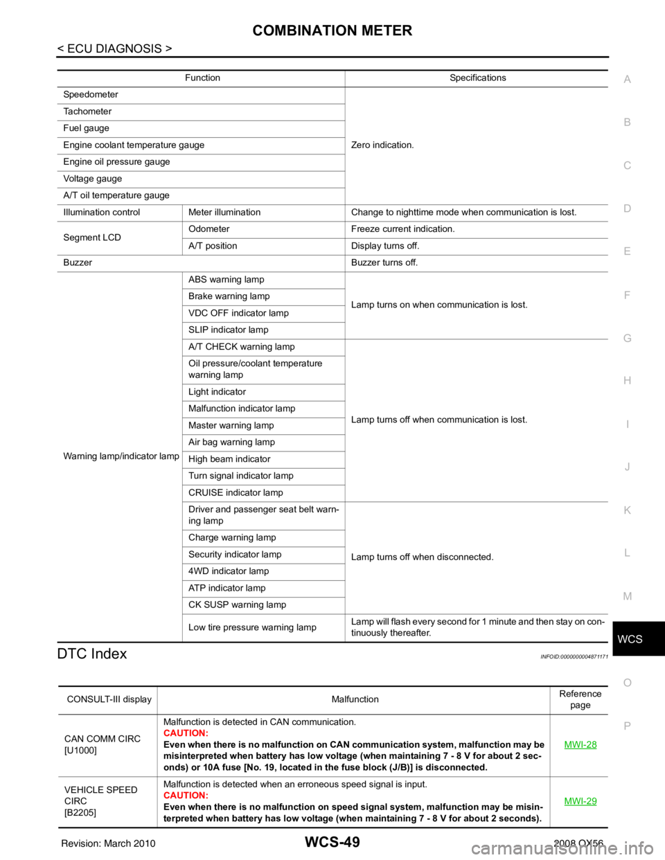
DTC IndexINFOID:0000000004871171
Function Specifications
Speedometer
Zero indication.
Tachometer
Fuel gauge
Engine coolant temperature gauge
Engine oil pressure gauge
Voltage gauge
A/T oil temperature gauge
Illumination control
Meter illumination Change to nighttime mode when communication is lost.
Segment LCD Odometer
Freeze current indication.
A/T position Display turns off.
Buzzer Buzzer turns off.
Warning lamp/indicator lamp ABS warning lamp
Lamp turns on when communication is lost.
Brake warning lamp
VDC OFF indicator lamp
SLIP indicator lamp
A/T CHECK warning lamp
Lamp turns off when communication is lost.
Oil pressure/coolant temperature
warning lamp
Light indicator
Malfunction indicator lamp
Master warning lamp
Air bag warning lamp
High beam indicator
Turn signal indicator lamp
CRUISE indicator lamp
Driver and passenger seat belt warn-
ing lamp
Lamp turns off when disconnected.
Charge warning lamp
Security indicator lamp
4WD indicator lamp
ATP indicator lamp
CK SUSP warning lamp
Low tire pressu
re warning lamp Lamp will flash every second for 1 minute and then stay on con-
tinuously thereafter.
CONSULT-III display
MalfunctionReference
page
CAN COMM CIRC
[U1000] Malfunction is detected in CAN communication.
CAUTION:
Even when there is no ma
lfunction on CAN communication system, malfunction may be
misinterpreted when battery has low voltag e (when maintaining 7 - 8 V for about 2 sec-
onds) or 10A fuse [No. 19, located in the fuse block (J/B)] is disconnected. MWI-28
VEHICLE SPEED
CIRC
[B2205]Malfunction is detected when an erroneous speed signal is input.
CAUTION:
Even when there is no malfunction on speed signal system, malfunction may be misin-
terpreted when battery has low voltage (whe
n maintaining 7 - 8 V for about 2 seconds). MWI-29
Revision: March 2010
2008 QX56
Page 3940 of 4083
WCS
BCM (BODY CONTROL MODULE)WCS-63
< ECU DIAGNOSIS >
C
DE
F
G H
I
J
K L
M B A
O P
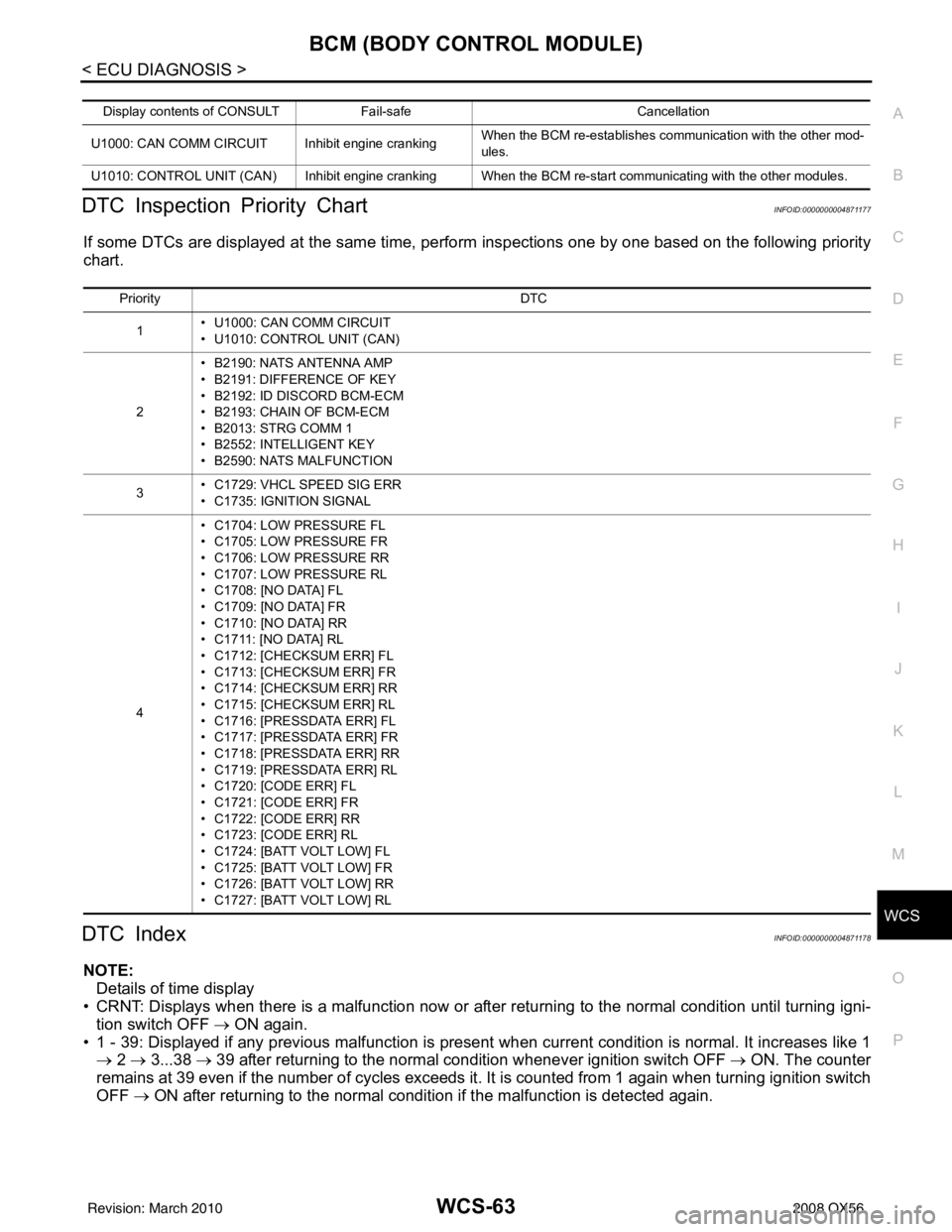
DTC Inspection Priority ChartINFOID:0000000004871177
If some DTCs are displayed at the same time, perform inspections one by one based on the following priority
chart.
DTC IndexINFOID:0000000004871178
NOTE: Details of time display
• CRNT: Displays when there is a malfunction now or after returning to the normal condition until turning igni-
tion switch OFF → ON again.
• 1 - 39: Displayed if any previous ma lfunction is present when current conditi on is normal. It increases like 1
→ 2 → 3...38 → 39 after returning to the normal condition whenever ignition switch OFF → ON. The counter
remains at 39 even if the number of cycles exceeds it. It is counted from 1 again when turning ignition switch
OFF → ON after returning to the normal condi tion if the malfunction is detected again.
Display contents of CONSULT Fail-safe Cancellation
U1000: CAN COMM CIRCUIT I nhibit engine crankingWhen the BCM re-establishes communication with the other mod-
ules.
U1010: CONTROL UNIT (CAN) Inhibit engine cranking When the BCM re-start communicating with the other modules.
Priority DTC
1 • U1000: CAN COMM CIRCUIT
• U1010: CONTROL UNIT (CAN)
2 • B2190: NATS ANTENNA AMP
• B2191: DIFFERENCE OF KEY
• B2192: ID DISCORD BCM-ECM
• B2193: CHAIN OF BCM-ECM
• B2013: STRG COMM 1
• B2552: INTELLIGENT KEY
• B2590: NATS MALFUNCTION
3 • C1729: VHCL SPEED SIG ERR
• C1735: IGNITION SIGNAL
4 • C1704: LOW PRESSURE FL
• C1705: LOW PRESSURE FR
• C1706: LOW PRESSURE RR
• C1707: LOW PRESSURE RL
• C1708: [NO DATA] FL
• C1709: [NO DATA] FR
• C1710: [NO DATA] RR
• C1711: [NO DATA] RL
• C1712: [CHECKSUM ERR] FL
• C1713: [CHECKSUM ERR] FR
• C1714: [CHECKSUM ERR] RR
• C1715: [CHECKSUM ERR] RL
• C1716: [PRESSDATA ERR] FL
• C1717: [PRESSDATA ERR] FR
• C1718: [PRESSDATA ERR] RR
• C1719: [PRESSDATA ERR] RL
• C1720: [CODE ERR] FL
• C1721: [CODE ERR] FR
• C1722: [CODE ERR] RR
• C1723: [CODE ERR] RL
• C1724: [BATT VOLT LOW] FL
• C1725: [BATT VOLT LOW] FR
• C1726: [BATT VOLT LOW] RR
• C1727: [BATT VOLT LOW] RL
Revision: March 2010
2008 QX56
Page 3998 of 4083
WW-1
DRIVER CONTROLS
C
DE
F
G H
I
J
K
M
SECTION WW
A
B
WW
N
O P
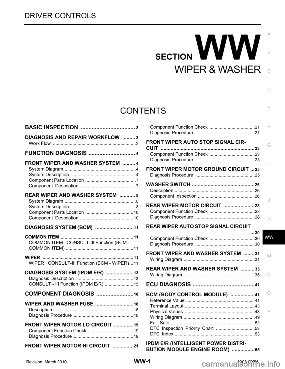
CONTENTS
WIPER & WASHER
BASIC INSPECTION ....... .............................3
DIAGNOSIS AND REPAIR WORKFLOW ..... .....3
Work Flow ........................................................... ......3
FUNCTION DIAGNOSIS ...............................4
FRONT WIPER AND WASHER SYSTEM ..... .....4
System Diagram .................................................. ......4
System Description ...................................................4
Component Parts Location ........................................7
Component Description ............................................7
REAR WIPER AND WASHER SYSTEM ............8
System Diagram .................................................. ......8
System Description ...................................................8
Component Parts Location ......................................10
Component Description ..........................................10
DIAGNOSIS SYSTEM (BCM) ............................11
COMMON ITEM ..................................................... ....11
COMMON ITEM : CONSULT-III Function (BCM -
COMMON ITEM) .....................................................
11
WIPER ................................................................... ....11
WIPER : CONSULT-III Function (BCM - WIPER) ....11
DIAGNOSIS SYSTEM (IPDM E/R) .....................13
Diagnosis Description ......................................... ....13
CONSULT - III Function (IPDM E/R) .......................15
COMPONENT DIAGNOSIS .........................18
WIPER AND WASHER FUSE ........................ ....18
Description .......................................................... ....18
Diagnosis Procedure ...............................................18
FRONT WIPER MOTOR LO CIRCUIT ...............19
Component Function Check ................................ ....19
Diagnosis Procedure ...............................................19
FRONT WIPER MOTOR HI CIRCUIT ................21
Component Function Check ................................ ....21
Diagnosis Procedure ...............................................21
FRONT WIPER AUTO STOP SIGNAL CIR-
CUIT ..................................................................
23
Component Function Check ....................................23
Diagnosis Procedure ...............................................23
FRONT WIPER MOTOR GROUND CIRCUIT ...25
Diagnosis Procedure ...............................................25
WASHER SWITCH ............................................26
Description ...............................................................26
Component Inspection .............................................26
REAR WIPER MOTOR CIRCUIT ......................28
Component Function Check ....................................28
Diagnosis Procedure ...............................................28
REAR WIPER AUTO STOP SIGNAL CIRCUIT
...
30
Component Function Check ................................ ....30
Diagnosis Procedure ...............................................30
FRONT WIPER AND WASHER SYSTEM ........31
Wiring Diagram ........................................................31
REAR WIPER AND WASHER SYSTEM ..........35
Wiring Diagram ........................................................35
ECU DIAGNOSIS .........................................41
BCM (BODY CONTROL MODULE) .................41
Reference Value .................................................. ....41
Terminal Layout .......................................................43
Physical Values ................................................... ....43
Wiring Diagram ........................................................49
Fail Safe ..................................................................52
DTC Inspection Priority Chart ...............................53
DTC Index ...............................................................53
IPDM E/R (INTELLIGENT POWER DISTRI-
BUTION MODULE ENGINE ROOM) ................
55
Revision: March 2010 2008 QX56
Page 4010 of 4083
DIAGNOSIS SYSTEM (IPDM E/R)WW-13
< FUNCTION DIAGNOSIS >
C
DE
F
G H
I
J
K
M A
B
WW
N
O P
DIAGNOSIS SYSTEM (IPDM E/R)
Diagnosis DescriptionINFOID:0000000004874864
AUTO ACTIVE TEST
Description
In auto active test mode, the IPDM E/R sends a drive signal to the following systems to check their operation.
• Oil pressure low/coolant pressure high warning indicator
• Oil pressure gauge
• Rear window defogger
• Front wipers
• Tail, license and parking lamps
• Front fog lamps
• Headlamps (Hi, Lo)
• A/C compressor (magnetic clutch)
• Cooling fan
Operation Procedure
1. Close the hood and front door RH, and lift the wiper arms from the windshield (to prevent windshield dam-
age due to wiper operation).
NOTE:
When auto active test is performed with hood opened, sprinkle water on windshield before hand.
2. Turn ignition switch OFF.
3. Turn the ignition switch ON and, within 20 seconds, press the front door switch LH 10 times. Then turn the ignition switch OFF.
4. Turn the ignition switch ON within 10 seconds. Af ter that the horn sounds once and the auto active test
starts.
5. After a series of the following operations is repeated 3 times, auto active test is completed.
NOTE:
When auto active test mode has to be cancelled halfway through test, turn ignition switch OFF.
CAUTION:
• If auto active test mode cannot be actua ted, check door switch system. Refer to DLK-67, "
Descrip-
tion".
• Do not start the engine.
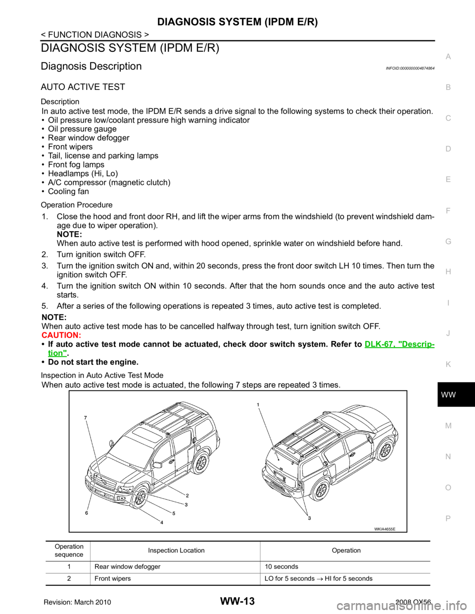
Inspection in Auto Active Test Mode
When auto active test mode is actuated, the following 7 steps are repeated 3 times.
Operation
sequence Inspection Location
Operation
1 Rear window defogger 10 seconds
2 Front wipers LO for 5 seconds → HI for 5 seconds
WKIA4655E
Revision: March 2010 2008 QX56
Page 4050 of 4083
BCM (BODY CONTROL MODULE)WW-53
< ECU DIAGNOSIS >
C
DE
F
G H
I
J
K
M A
B
WW
N
O P
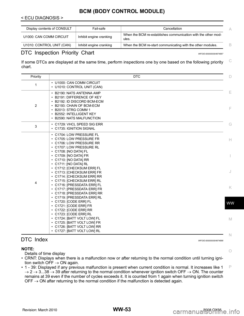
DTC Inspection Priority ChartINFOID:0000000004874897
If some DTCs are displayed at the same time, perform inspections one by one based on the following priority
chart.
DTC IndexINFOID:0000000004874898
NOTE: Details of time display
• CRNT: Displays when there is a malfunction now or after returning to the normal condition until turning igni-
tion switch OFF → ON again.
• 1 - 39: Displayed if any previous ma lfunction is present when current conditi on is normal. It increases like 1
→ 2 → 3...38 → 39 after returning to the normal condition whenever ignition switch OFF → ON. The counter
remains at 39 even if the number of cycles exceeds it. It is counted from 1 again when turning ignition switch
OFF → ON after returning to the normal condi tion if the malfunction is detected again.
Display contents of CONSULT Fail-safe Cancellation
U1000: CAN COMM CIRCUIT I nhibit engine crankingWhen the BCM re-establishes communication with the other mod-
ules.
U1010: CONTROL UNIT (CAN) Inhibit engine cranking When the BCM re-start communicating with the other modules.
Priority DTC
1 • U1000: CAN COMM CIRCUIT
• U1010: CONTROL UNIT (CAN)
2 • B2190: NATS ANTENNA AMP
• B2191: DIFFERENCE OF KEY
• B2192: ID DISCORD BCM-ECM
• B2193: CHAIN OF BCM-ECM
• B2013: STRG COMM 1
• B2552: INTELLIGENT KEY
• B2590: NATS MALFUNCTION
3 • C1729: VHCL SPEED SIG ERR
• C1735: IGNITION SIGNAL
4 • C1704: LOW PRESSURE FL
• C1705: LOW PRESSURE FR
• C1706: LOW PRESSURE RR
• C1707: LOW PRESSURE RL
• C1708: [NO DATA] FL
• C1709: [NO DATA] FR
• C1710: [NO DATA] RR
• C1711: [NO DATA] RL
• C1712: [CHECKSUM ERR] FL
• C1713: [CHECKSUM ERR] FR
• C1714: [CHECKSUM ERR] RR
• C1715: [CHECKSUM ERR] RL
• C1716: [PRESSDATA ERR] FL
• C1717: [PRESSDATA ERR] FR
• C1718: [PRESSDATA ERR] RR
• C1719: [PRESSDATA ERR] RL
• C1720: [CODE ERR] FL
• C1721: [CODE ERR] FR
• C1722: [CODE ERR] RR
• C1723: [CODE ERR] RL
• C1724: [BATT VOLT LOW] FL
• C1725: [BATT VOLT LOW] FR
• C1726: [BATT VOLT LOW] RR
• C1727: [BATT VOLT LOW] RL
Revision: March 2010
2008 QX56