2008 INFINITI QX56 check engine
[x] Cancel search: check enginePage 3740 of 4083
ROAD TESTTM-193
< ON-VEHICLE MAINTENANCE >
CEF
G H
I
J
K L
M A
B
TM
N
O P
When the transmission changes speed D3 → D4, return the accelerator pedal.
Does the A/T shift-up D3
→ D4 and apply the engine brake?
YES >> 1. Stop the vehicle. 2. See TM-193, "
Cruise Test - Part 3".
NO >> Enter a check mark at “Vehicle Does Not Shift: D3 → D4” on the diagnostics worksheet, then con-
tinue the road test.
Cruise Test - Part 3INFOID:0000000001696163
1.CHECK SHIFT-DOWN
During D
5 driving, move gear selector from D → 4 → 3 → 2 → 1.
With CONSULT-III
Read the gear position.
Is downshifting correctly performed?
YES >> GO TO 2.
NO >> Enter a check mark at “Vehicle does not shift” at the corresponding position (5th → 4th, 4th → 3rd,
3rd → 2nd, 2nd → 1st) on the diagnostics worksheet, then continue the road test.
2.CHECK ENGINE BRAKE
Does engine braking effectively reduce speed in 1
1 position?
YES >> 1. Stop the vehicle. 2. Carry out the self-diagnostics. Refer to TM-32, "
CONSULT-III Function (TRANSMISSION)".
NO >> Enter a check mark at “Vehicle Does Not Decelerate By Engine Brake” on the diagnostics work- sheet, then continue trouble diagnosis.
Vehicle Speed When Shifting GearsINFOID:0000000001696164
Refer to TM-193, "Vehicle Speed When Shifting Gears".
Vehicle Speed When Performing and Releasing Complete Lock-upINFOID:0000000001696165
Refer to TM-193, "Vehicle Speed When Performing and Releasing Complete Lock-up".
Revision: March 2010 2008 QX56
Page 3741 of 4083
TM-194
< ON-VEHICLE MAINTENANCE >
A/T POSITION
A/T POSITION
Checking of A/T PositionINFOID:0000000004917429
With the shift selector in the “P” position, turn the ignition switch to the ON position with the engine OFF.
Confirm that the following conditions apply.
• The shift selector can be shifted from the “P ” position only when the brake pedal is depressed.
• The shift selector stops at each position with the feel of engagement when it is moved through all the posi-
tions.
• There is no excessive effort, sticking, noise or rattle.
• The actual position of the shift selector matches the position shown by the shift position indicator and the A/
T body.
• The back-up lamps illuminate only when the shift selector is placed in the “R” position.
• The back-up lamps do not illuminate when the shift selector is pushed against the “R” position when in the
“P” or “N” position.
• The engine can only be started with the shift selector in the “P” and “N” positions.
• The A/T is locked completely when in the “P” position.
Adjustment of A/T PositionINFOID:0000000004917428
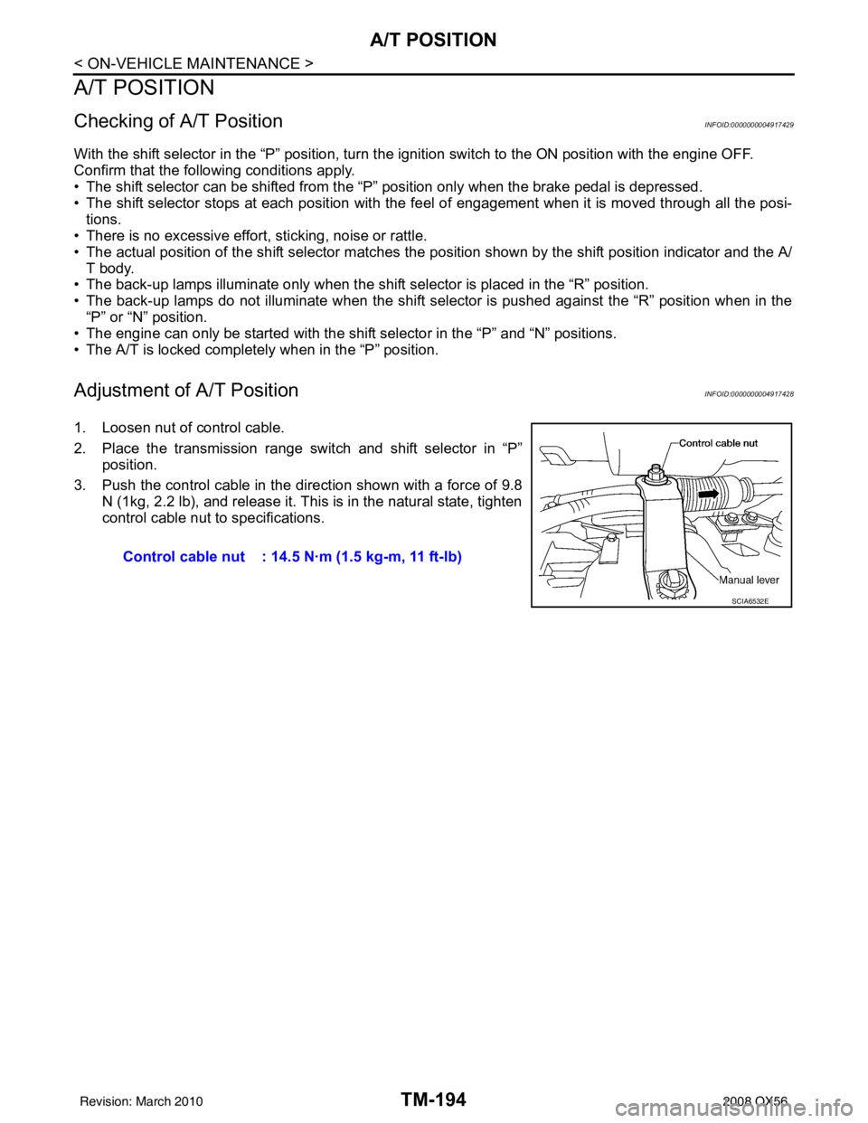
1. Loosen nut of control cable.
2. Place the transmission range switch and shift selector in “P”
position.
3. Push the control cable in the di rection shown with a force of 9.8
N (1kg, 2.2 lb), and release it. This is in the natural state, tighten
control cable nut to specifications.
Control cable nut : 14.5 N·m (1.5 kg-m, 11 ft-lb)
SCIA6532E
Revision: March 2010 2008 QX56
Page 3743 of 4083
TM-196
< ON-VEHICLE REPAIR >
SHIFT CONTROL SYSTEM
Checking of A/T Position
INFOID:0000000004917432
1. Place shift selector in “P” position, and turn ignition switch ON (engine stop).
2. Make sure shift selector can be shifted to other than “P” position when brake pedal is depressed. Also make sure shift selector
can be shifted from “P” position only when brake pedal is
depressed.
3. Move the shift selector and check for excessive effort, sticking, noise or rattle.
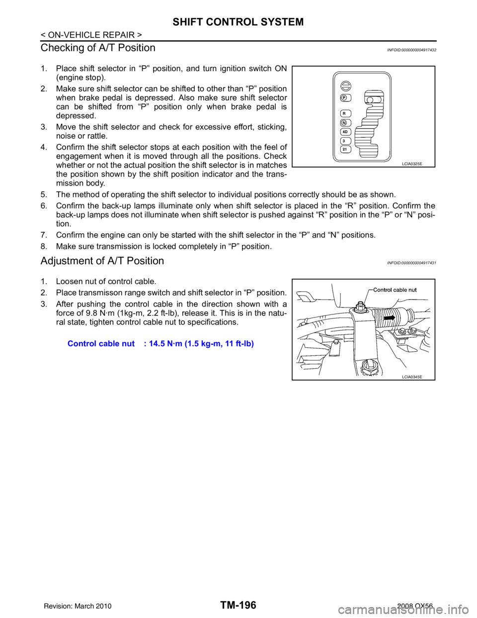
4. Confirm the shift selector stop s at each position with the feel of
engagement when it is moved through all the positions. Check
whether or not the actual position the shift selector is in matches
the position shown by the shift position indicator and the trans-
mission body.
5. The method of operating the shift selector to individual positions correctly should be as shown.
6. Confirm the back-up lamps illuminate only when shift sele ctor is placed in the “R” position. Confirm the
back-up lamps does not illuminate when shift selector is pushed against “R” position in the “P” or “N” posi-
tion.
7. Confirm the engine can only be started with the shift selector in the “P” and “N” positions.
8. Make sure transmission is locked completely in “P” position.
Adjustment of A/T PositionINFOID:0000000004917431
1. Loosen nut of control cable.
2. Place transmisson range switch and shift selector in “P” position.
3. After pushing the control cable in the direction shown with a force of 9.8 N·m (1kg-m, 2.2 ft-lb), release it. This is in the natu-
ral state, tighten control cable nut to specifications.
LCIA0325E
Control cable nut : 14.5 N·m (1.5 kg-m, 11 ft-lb)
LCIA0345E
Revision: March 2010 2008 QX56
Page 3762 of 4083
TRANSMISSION ASSEMBLYTM-215
< REMOVAL AND INSTALLATION >
CEF
G H
I
J
K L
M A
B
TM
N
O P
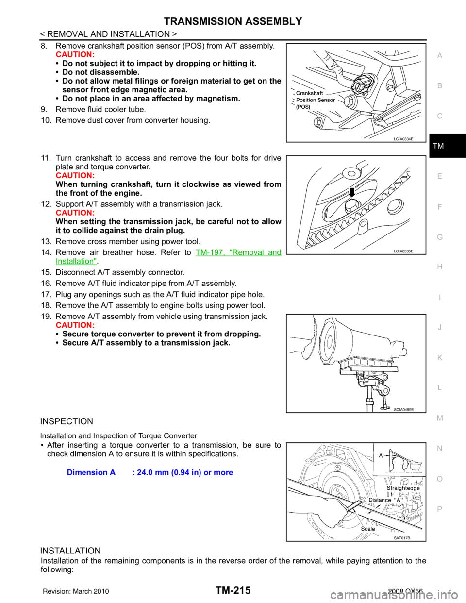
8. Remove crankshaft position sens or (POS) from A/T assembly.
CAUTION:
• Do not subject it to impact by dropping or hitting it.
• Do not disassemble.
• Do not allow metal filings or foreign material to get on the
sensor front edge magnetic area.
• Do not place in an area affected by magnetism.
9. Remove fluid cooler tube.
10. Remove dust cover from converter housing.
11. Turn crankshaft to access and remove the four bolts for drive plate and torque converter.
CAUTION:
When turning crankshaft, turn it clockwise as viewed from
the front of the engine.
12. Support A/T assembly with a transmission jack. CAUTION:
When setting the transmission jack, be careful not to allow
it to collide agai nst the drain plug.
13. Remove cross member using power tool.
14. Remove air breather hose. Refer to TM-197, "
Removal and
Installation".
15. Disconnect A/T assembly connector.
16. Remove A/T fluid indicator pipe from A/T assembly.
17. Plug any openings such as the A/T fluid indicator pipe hole.
18. Remove the A/T assembly to engine bolts using power tool.
19. Remove A/T assembly from vehicle using transmission jack. CAUTION:
• Secure torque converter to prevent it from dropping.
• Secure A/T assembly to a transmission jack.
INSPECTION
Installation and Inspection of Torque Converter
• After inserting a torque converter to a transmission, be sure to check dimension A to ensure it is within specifications.
INSTALLATION
Installation of the remaining components is in the revers e order of the removal, while paying attention to the
following:
LCIA0334E
LCIA0335E
SCIA0499E
Dimension A : 24.0 mm (0.94 in) or more
SAT017B
Revision: March 2010 2008 QX56
Page 3763 of 4083
TM-216
< REMOVAL AND INSTALLATION >
TRANSMISSION ASSEMBLY
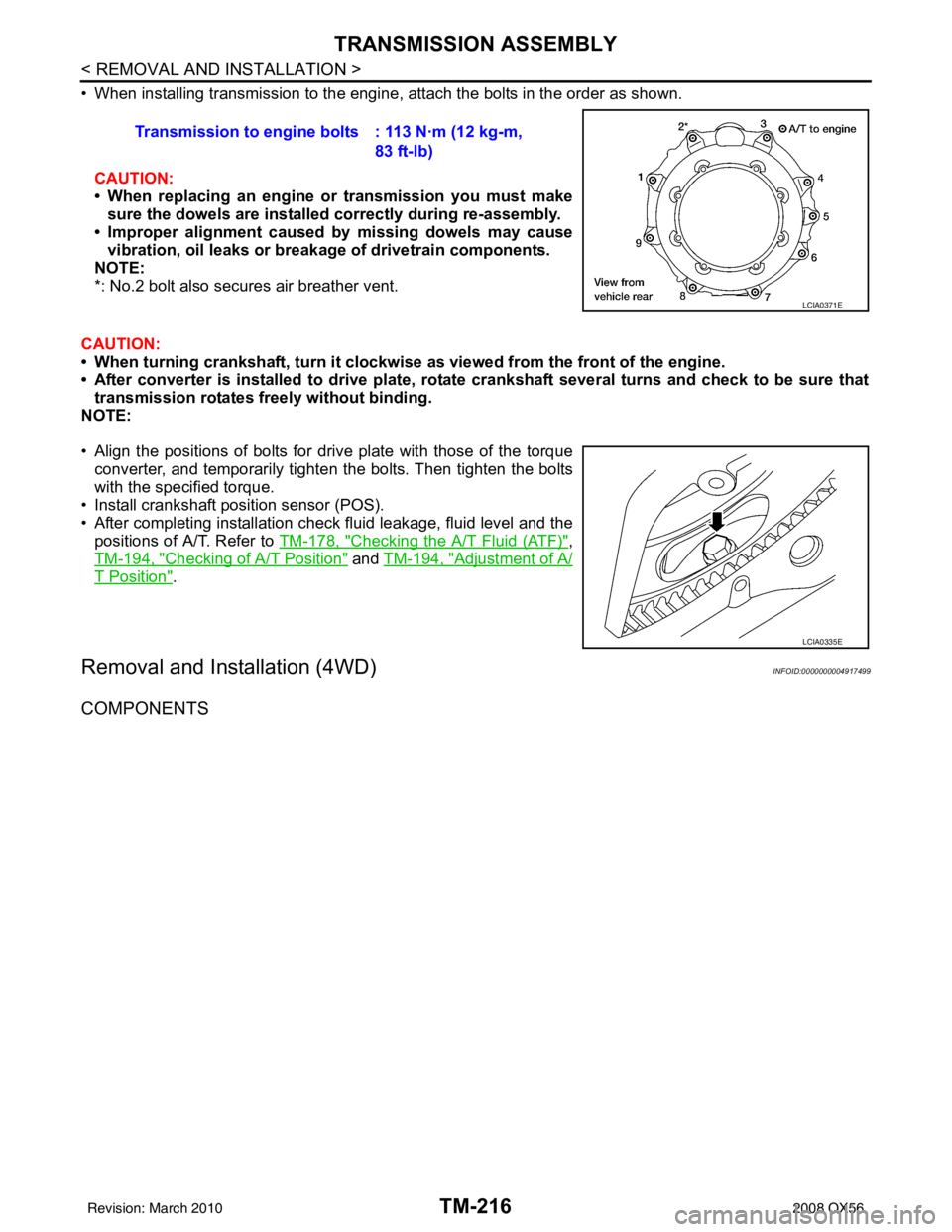
• When installing transmission to the engine, attach the bolts in the order as shown.CAUTION:
• When replacing an engine or transmission you must make
sure the dowels are installe d correctly during re-assembly.
• Improper alignment caused by missing dowels may cause
vibration, oil leaks or breakage of drivetrain components.
NOTE:
*: No.2 bolt also secures air breather vent.
CAUTION:
• When turning crankshaft, turn it clockwi se as viewed from the front of the engine.
• After converter is installed to drive plate, rota te crankshaft several turns and check to be sure that
transmission rotates fr eely without binding.
NOTE:
• Align the positions of bolts for drive plate with those of the torque converter, and temporarily tighten the bolts. Then tighten the bolts
with the specified torque.
• Install crankshaft pos ition sensor (POS).
• After completing installation check fluid leakage, fluid level and the positions of A/T. Refer to TM-178, "
Checking the A/T Fluid (ATF)",
TM-194, "
Checking of A/T Position" and TM-194, "Adjustment of A/
T Position".
Removal and Installation (4WD)INFOID:0000000004917499
COMPONENTS
Transmission to engine bolts : 113 N·m (12 kg-m,
83 ft-lb)
LCIA0371E
LCIA0335E
Revision: March 2010 2008 QX56
Page 3766 of 4083
TRANSMISSION ASSEMBLYTM-219
< REMOVAL AND INSTALLATION >
CEF
G H
I
J
K L
M A
B
TM
N
O P
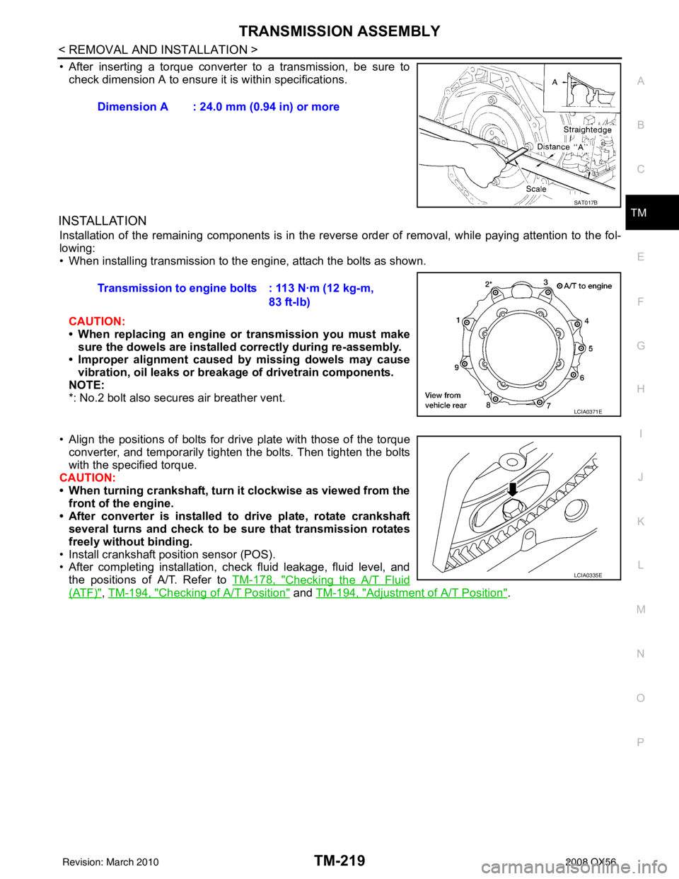
• After inserting a torque converter to a transmission, be sure to check dimension A to ensure it is within specifications.
INSTALLATION
Installation of the remaining components is in the revers e order of removal, while paying attention to the fol-
lowing:
• When installing transmission to the engine, attach the bolts as shown.
CAUTION:
• When replacing an engine or transmission you must make sure the dowels are installed correctly during re-assembly.
• Improper alignment caused by missing dowels may cause
vibration, oil leaks or breakage of drivetrain components.
NOTE:
*: No.2 bolt also secures air breather vent.
• Align the positions of bolts for dr ive plate with those of the torque
converter, and temporarily tighten the bolts. Then tighten the bolts
with the specified torque.
CAUTION:
• When turning crankshaft, turn it clockwise as viewed from the
front of the engine.
• After converter is installed to drive plate, rotate crankshaft several turns and check to be sure that transmission rotates
freely without binding.
• Install crankshaft position sensor (POS).
• After completing installation, check fluid leakage, fluid level, and the positions of A/T. Refer to TM-178, "
Checking the A/T Fluid
(ATF)", TM-194, "Checking of A/T Position" and TM-194, "Adjustment of A/T Position".
Dimension A : 24.0 mm (0.94 in) or more
SAT017B
Transmission to engine bolts : 113 N·m (12 kg-m,
83 ft-lb)
LCIA0371E
LCIA0335E
Revision: March 2010 2008 QX56
Page 3857 of 4083
HEATER & COOLING UNIT ASSEMBLYVTL-17
< ON-VEHICLE REPAIR >
C
DE
F
G H
J
K L
M A
B
VTL
N
O P
1. Move the two front seats to the rear most position on the seat track.
2. Disconnect the battery negative terminal and battery positive terminal.
3. Discharge the refrigerant from the A/C system. Refer to HA-20, "
HFC-134a (R-134a) Service Procedure".
4. Drain the coolant from the engine cooling system. Refer to CO-11, "
Changing Engine Coolant".
5. Disconnect the front heater hoses from the front heater core.
6. Disconnect the high/low pressure pipes from the front expansion valve.
7. Remove the instrument panel and console panel. Refer to IP-12, "
Removal and Installation".
8. Remove the steering column. Refer to ST-20, "
Removal and Installation".
9. Disconnect the instrument panel wire harness at t he RH and LH in-line connector brackets, and the fuse
block (J/B) electrical connectors. Refer to PG-9, "
Wiring Diagram — Battery Power Supply —".
10. Disconnect the steering member from each side of the vehicle body.
11. Remove the front heater and cooling unit assembly with it attached to the steering member, from the vehi- cle.
CAUTION:
Use care not to damage the seats and interior trim panels when removing the front heater and
cooling unit assembly with it at tached to the steering member.
12. Remove the front heater and cooling uni t assembly from the steering member.
Installation
Installation is in the reverse order of removal.
CAUTION:
• Replace the O-ring of the low-pressure pipe and high-pressure pipe with a new one, and apply com-
pressor oil to it when installing it.
• After charging the refrigerant, check for leaks.
NOTE:
• Fill the engine cooling system with the specified coolant mixture. Refer to CO-11, "
Changing Engine Cool-
ant".
• Recharge the A/C system. Refer to HA-20, "
HFC-134a (R-134a) Service Procedure".
REAR HEATER AND COOLING UNIT ASSEMBLY
Removal
1. Discharge the refrigerant from the A/C system. Refer to HA-20, "HFC-134a (R-134a) Service Procedure".
2. Drain the coolant from the engine cooling system. Refer to CO-11, "
Changing Engine Coolant".
3. Remove the luggage side finisher lower RH. Refer to INT-19, "
Removal and Installation".
4. Disconnect the rear heater core hoses from the rear heater core.
5. Disconnect the rear A/C pipes from the rear expansion valve.
6. Disconnect the following electrical connectors: • Rear blower motor
• Rear variable blower control
• Rear air mix door motor
7. Disconnect the ducts from the rear heater and cooling unit assembly.
8. Remove the rear heater and cooling unit assembly.
Installation
Installation is in the reverse order of removal.
CAUTION:
• Replace the O-ring of the low-pressure pipe and high-pressure pipe with a new one, and apply com- pressor oil to it when installing it.
• After charging the refrigerant, check for leaks.
NOTE:
• Fill the engine cooling system with the specified coolant mixture. Refer to CO-11, "
Changing Engine Cool-
ant".
• Recharge the A/C system. Refer to HA-20, "
HFC-134a (R-134a) Service Procedure".
Revision: March 2010 2008 QX56
Page 3891 of 4083
![INFINITI QX56 2008 Factory Service Manual WCS-14
< FUNCTION DIAGNOSIS >
DIAGNOSIS SYSTEM (METER)
X: Applicable
Display item [Unit]MAIN
SIGNALS SELECTION
FROM MENU Description
SPEED METER [km/h] or [mph] X X Displays the value of vehicle spee INFINITI QX56 2008 Factory Service Manual WCS-14
< FUNCTION DIAGNOSIS >
DIAGNOSIS SYSTEM (METER)
X: Applicable
Display item [Unit]MAIN
SIGNALS SELECTION
FROM MENU Description
SPEED METER [km/h] or [mph] X X Displays the value of vehicle spee](/manual-img/42/57030/w960_57030-3890.png)
WCS-14
< FUNCTION DIAGNOSIS >
DIAGNOSIS SYSTEM (METER)
X: Applicable
Display item [Unit]MAIN
SIGNALS SELECTION
FROM MENU Description
SPEED METER [km/h] or [mph] X X Displays the value of vehicle speed signal.
SPEED OUTPUT [km/h] or [mph] X XDisplays the value of vehicle speed signal, which is transmitted to
each unit with
CAN communication.
TACHO METER [rpm] XX Displays the value of engine speed signal, which is input from ECM.
FUEL METER [lit.] XXDisplays the value, which processes a resistance signal from fuel
gauge.
W TEMP METER [ °C] or [° F] X XDisplays the value of engine coolant temperature signal, which is in-
put from ECM.
ABS W/L [ON/OFF] X Displays [ON/OFF] condition of ABS warning lamp.
VDC/TCS IND [ON/OFF] X Displays [ON/OFF] condition of VDC OFF indicator lamp.
SLIP IND [ON/OFF] X Displays [ON/OFF] condition of SLIP indicator lamp.
BRAKE W/L [ON/OFF] X Displays [ON/OFF] condition of brake warning lamp.*
DOOR W/L [ON/OFF] X Displays [ON/OFF] condition of door warning lamp.
TRUNK W/L [ON/OFF] X Displays [ON/OFF] condition of glass hatch warning lamp.
HI-BEAM IND [ON/OFF] X Displays [ON/OFF] condition of high beam indicator.
TURN IND [ON/OFF] X Displays [ON/OFF] conditio n of turn indicator.
OIL W/L [ON/OFF] X Displays [ON/OFF] condition of oil pressure warning lamp.
C-ENG W/L [ON/OFF] X Displays [ON/OFF] condition of malfunction indicator lamp.
CRUISE IND [ON/OFF] X Displays [ON/OFF] condition of CRUISE indicator.
SET IND [ON/OFF] X Displays [ON/OFF] condition of SET indicator.
AT CHECK W/L [ON/OFF] X Displays [ON/OFF] condition of AT CHECK warning lamp.
FUEL W/L [ON/OFF] XX Displays [ON/OFF] condition of low-fuel warning lamp.
AIR PRES W/L [ON/OFF] X Displays [ON/OFF] condition of tire pressure warning lamp.
KEY G W/L [ON/OFF] X Displays [ON/OFF] condition of key green warning lamp.
KEY R W/L [ON/OFF] X Displays [ON/OFF] condition of key red warning lamp.
KEY KNOB W/L [ON/OFF] X Displays [ON/OFF] condition of key knob warning lamp.
M RANGE SW [ON/OFF] XX Displays [ON/OFF] condition of manual mode range switch.
NM RANGE SW [ON/OFF] XXDisplays [ON/OFF] condition of except for manual mode range
switch.
AT SFT UP SW [ON/OFF] XX Displays [ON/OFF] condition of A/T shift-up switch.
AT SFT DWN SW [ON/OFF] XX Displays [ON/OF F] condition of A/T shift-down switch.
DISTANCE [km] or [mile] XXDisplays the value, which is calculated by vehicle speed signal, fuel
gauge and fuel consumption from ECM.
BUZZER [ON/OFF] XX Displays [ON/ OFF] condition of buzzer.
BRAKE SW [ON/OFF] X Indicates [ON/OFF] condition of parking brake switch.
AT-M GEAR [1, 2, 3, 4, 5] XX Indicates [1, 2, 3, 4, 5] condition of A/T manual mode gear position.
P RANGE IND [ON/OFF] XX Indicates [ON/OFF] condition of A/T shift P range indicator.
R RANGE IND [ON/OFF] XX Indicates [ON/OFF] condition of A/T shift R range indicator.
N RANGE IND [ON/OFF] XX Indicates [ON/OFF] condition of A/T shift N range indicator.
D RANGE IND [ON/OFF] XX Indicates [ON/OFF] condition of A/T shift D range indicator.
4 RANGE IND [ON/OFF] XX Indicates [ON/OFF] condition of A/T shift 4 range indicator.
3 RANGE IND [ON/OFF] XX Indicates [ON/OFF] condition of A/T shift 3 range indicator.
2 RANGE IND [ON/OFF] XX Indicates [ON/OFF] condition of A/T shift 2 range indicator.
1 RANGE IND [ON/OFF] XX Indicates [ON/OFF] condition of A/T shift 1range indicator.
Revision: March 2010 2008 QX56