2008 INFINITI QX56 battery
[x] Cancel search: batteryPage 2396 of 4083

DIAGNOSIS SYSTEM (BCM)INL-13
< FUNCTION DIAGNOSIS >
C
DE
F
G H
I
J
K
M A
B
INL
N
O P
BATTERY SAVER
BATTERY SAVER : CONSULT-III FunctionINFOID:0000000001601385
WORK SUPPORT
DATA MONITOR
ACTIVE TEST
LUGGAGE LAMP TEST ON Outputs the cargo lamp control signal to turn cargo lamp ON.
OFF Stops the cargo lamp control signal to turn cargo lamp OFF.
Test item
Operation Description
Service itemSetting item Setting
ROOM LAMP TIMER SET MODE 1
(ON)
Interior room lamp timer activates with synchronizing all doors.
MODE 2
(OFF) Interior room lamp timer activates with synchronizing the front door LH
only.
Monitor item
[Unit] Description
IGN ON SW
[ON/OFF] The switch status input from ignition switch
KEY ON SW
[ON/OFF] Key switch status input from key slot
DOOR SW-DR
[ON/OFF] The switch status input from front door switch LH
DOOR SW-AS
[ON/OFF] The switch status input from front door switch RH
DOOR SW-RR
[ON/OFF] The switch status input from rear door switch RH
DOOR SW- RL
[ON/OFF] The switch status input from rear door switch LH
BACK DOOR SW
[ON/OFF] The switch status input from back door switch
KEY CYL LK-SW
[ON/OFF] Lock switch status received from key cylinder switch by power window serial link
KEY CYL UN-SW
[ON/OFF] Unlock switch status received from key cylinder switch by power window serial link
CDL LOCK SW
[ON/OFF] Lock switch status received from door lock/unlock switch by power window serial link
CDL UNLOCK SW
[ON/OFF] Unlock switch status received from door lock/unlock switch by power window serial
link
I-KEY LOCK
[ON/OFF] Lock signal status received from remote keyless entry receiver
I-KEY UNLOCK
[ON/OFF] Unlock signal status received from remote keyless entry receiver
Test item
Operation Description
BATTERY SAVER ON Outputs the battery saver output/power supply to turn the interior lamps ON.
OFF Stops the battery saver output/power supply to turn the interior lamps OFF.
Revision: March 2010 2008 QX56
Page 2398 of 4083

INTERIOR ROOM LAMP POWER SUPPLY CIRCUIT
INL-15
< COMPONENT DIAGNOSIS >
C
D E
F
G H
I
J
K
M A
B
INL
N
O P
INTERIOR ROOM LAMP POWER SUPPLY CIRCUIT
DescriptionINFOID:0000000001601387
Provides the battery saver output/power supply. Also cu ts the power supply when the interior room lamp bat-
tery saver is activating.
Component Function CheckINFOID:0000000001601388
1.CHECK BATTERY SAVER OUTPUT /POWER SUPPLY FUNCTION
CONSULT-III
1. Turn ignition switch ON.
2. Turn each interior room lamp ON.
- Front room/map lamp assembly
- Vanity lamps
- Personal lamp 2nd row
- Personal lamp 3rd row
- Cargo lamp
3. Open the driver door to turn ON the step lamps, foot lamps and puddle lamps.
- Front step lamps
- Rear step lamps
- Foot lamps
- Puddle lamps
- Ignition keyhole Illumination
4. Select “BATTERY SAVER” of BCM (BATTERY SAVER) active test item.
5. While operating the test item, check that each interior room lamp turns ON/OFF.
Is the inspection result normal?
YES >> Battery saver output/power supply circuit is normal.
NO >> Refer to INL-15, "
Diagnosis Procedure".
Diagnosis ProcedureINFOID:0000000001601389
1.CHECK BATTERY SAVER OUTPUT/POWER SUPPLY OUTPUT
CONSULT-III
1. Turn ignition switch ON.
2. Select “BATTERY SAVER” of BCM (BATTERY SAVER) active
test item.
3. While operating the test item, check voltage between BCM con-
nector M20 terminal 56 and ground.
Is the inspection result normal?
YES >> GO TO 2
NO >> Replace BCM. Refer to BCS-55, "
Removal and Installation".
2.CHECK BATTERY SAVER OUTPUT/P OWER SUPPLY OPEN CIRCUIT
1. Turn ignition switch OFF.
2. Disconnect the following connectors.
-BCM M20
- Ignition keyhole illumination OFF : Interior room lamps OFF
ON : Interior room lamps ON
(+)
(-)Te s t i t e m
Voltag e
Connector Terminal BATTERY SAVER
M20 56 Ground OFF
0V
ON Battery voltage
ALLIA0408GB
Revision: March 2010 2008 QX56
Page 2399 of 4083
INL-16
< COMPONENT DIAGNOSIS >
INTERIOR ROOM LAMP POWER SUPPLY CIRCUIT
- Front step lamp LH
- Front step lamp RH
- Door mirror LH
- Door mirror RH
- Rear step lamp LH
- Rear step lamp RH
- Foot lamp LH
- Foot lamp RH
- Front room/map lamp assembly
- Vanity lamp LH
- Vanity lamp RH
- Cargo lamp
- Personal lamp 2nd row
- Personal lamp 3rd row
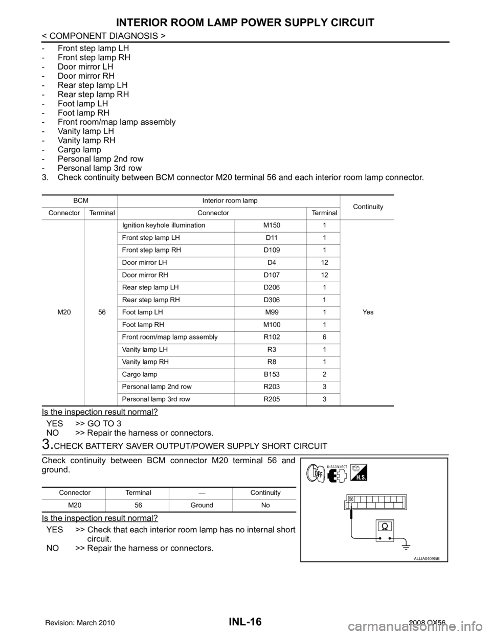
3. Check continuity between BCM connector M20 term inal 56 and each interior room lamp connector.
Is the inspection result normal?
YES >> GO TO 3
NO >> Repair the harness or connectors.
3.CHECK BATTERY SAVER OUTPUT/P OWER SUPPLY SHORT CIRCUIT
Check continuity between BCM connector M20 terminal 56 and
ground.
Is the inspection result normal?
YES >> Check that each interior room lamp has no internal short circuit.
NO >> Repair the harness or connectors.
BCM Interior room lamp
Continuity
Connector Terminal ConnectorTerminal
M20 56 Ignition keyhole illumination
M1501
Ye s
Front step lamp LH
D111
Front step lamp RH D1091
Door mirror LH D412
Door mirror RH D10712
Rear step lamp LH D2061
Rear step lamp RH D3061
Foot lamp LH M991
Foot lamp RH M1001
Front room/map lamp assembly R1026
Vanity lamp LH R31
Vanity lamp RH R81
Cargo lamp B1532
Personal lamp 2nd row R2033
Personal lamp 3rd row R2053
Connector Terminal —Continuity
M20 56Ground No
ALLIA0409GB
Revision: March 2010 2008 QX56
Page 2400 of 4083
INTERIOR ROOM LAMP CONTROL CIRCUITINL-17
< COMPONENT DIAGNOSIS >
C
DE
F
G H
I
J
K
M A
B
INL
N
O P
INTERIOR ROOM LAMP CONTROL CIRCUIT
DescriptionINFOID:0000000001601390
Controls the following interior room lamps (ground side) by PWM signal
• Puddle lamps
• Front room/map lamp assembly
• Personal lamp 2nd row
• Personal lamp 3rd row
NOTE:
PWM signal control period is approximately 250 Hz (in the gradual brightening/dimming).
Component Function CheckINFOID:0000000001601391
CAUTION:
Before performing the diagnosis, check that the following is normal.
• Battery saver output/power supply
• Front room/map lamp bulbs
• Personal lamp bulbs
• Puddle lamp bulbs
1.CHECK INTERIOR ROOM LAMP CONTROL FUNCTION
CONSULT-III
1. Switch the front room/map lamp assembly switch to DOOR.
2. Turn ignition switch ON.
3. Select “INT LAMP” of BCM (INT LAMP) active test item.
4. While operating the test item, check that each interi or room lamp turns ON/OFF (gradual brightening/dim-
ming).
Is the inspection result normal?
YES >> Interior room lamp control circuit is normal.
NO >> Refer to INL-17, "
Diagnosis Procedure".
Diagnosis ProcedureINFOID:0000000001601392
1.CHECK INTERIOR ROOM LAMP CONTROL OUTPUT
CONSULT-III
1. Switch the front room/map lamp assembly switch to DOOR.
2. Turn ignition switch ON.
3. Select “INT LAMP” of BCM (INT LAMP) active test item.
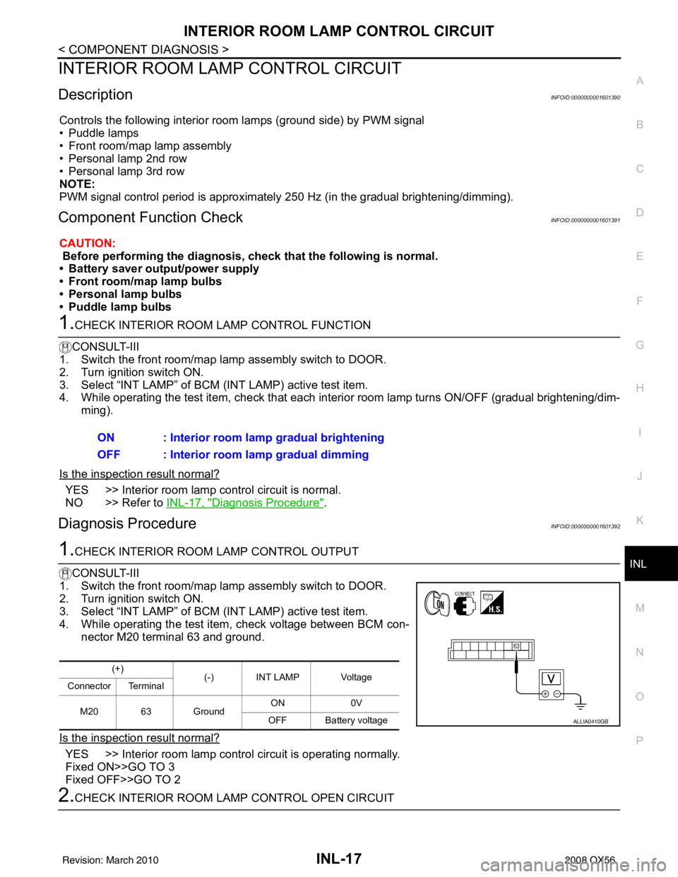
4. While operating the test item, check voltage between BCM con- nector M20 terminal 63 and ground.
Is the inspection result normal?
YES >> Interior room lamp control circuit is operating normally.
Fixed ON>>GO TO 3
Fixed OFF>>GO TO 2
2.CHECK INTERIOR ROOM LAMP CONTROL OPEN CIRCUIT ON : Interior room lamp gradual brightening
OFF : Interior room lamp gradual dimming
(+)
(-) INT LAMP Voltage
Connector Terminal
M20 63 Ground ON
0V
OFF Battery voltage
ALLIA0410GB
Revision: March 2010 2008 QX56
Page 2402 of 4083
STEP LAMP CIRCUITINL-19
< COMPONENT DIAGNOSIS >
C
DE
F
G H
I
J
K
M A
B
INL
N
O P
STEP LAMP CIRCUIT
DescriptionINFOID:0000000001601393
Controls the front and rear step lamps and the foot lamps (ground side) to turn the lamps ON and OFF.
Component Function CheckINFOID:0000000001601394
CAUTION:
Before performing the diagnosis, check that the following is normal.
• Battery saver output/power supply
• Front step lamp bulbs
• Rear step lamp bulbs
• Foot lamp bulbs
1.CHECK STEP LAMP OPERATION
CONSULT-III
1. Turn ignition switch ON.
2. Select “STEP LAMP TEST” of BC M (INT LAMP) active test item.
3. While operating the test item, check that the front/rear step lamps and foot lamps turn ON/OFF.
Is the inspection result normal?
YES >> Step lamp circuit is normal.
NO >> Refer to INL-19, "
Diagnosis Procedure".
Diagnosis ProcedureINFOID:0000000001601395
1.CHECK STEP LAMP OUTPUT
CONSULT-III
1. Turn ignition switch ON.
2. Select “STEP LAMP TEST” of BC M (INT LAMP) active test item.
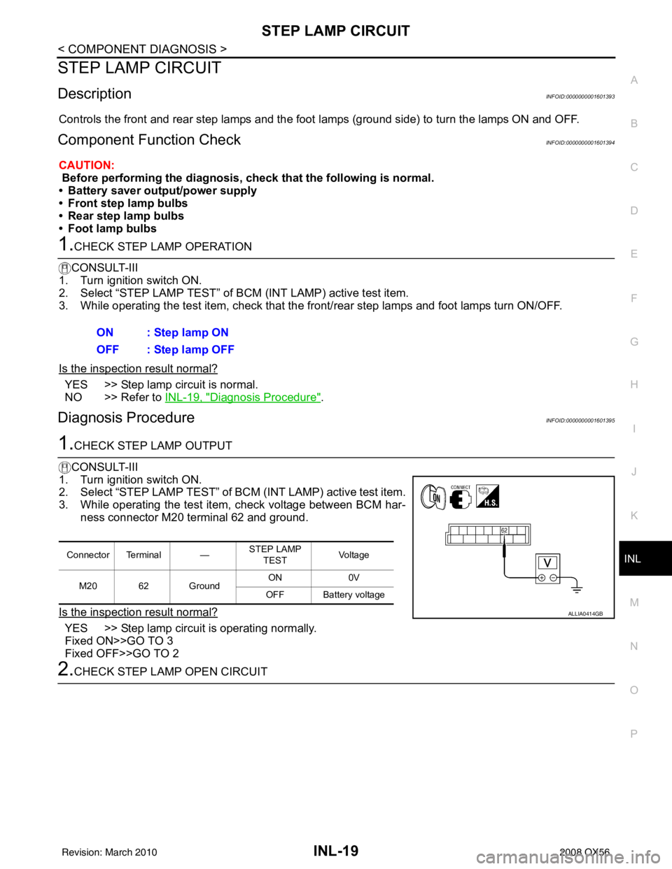
3. While operating the test item, check voltage between BCM har- ness connector M20 terminal 62 and ground.
Is the inspection result normal?
YES >> Step lamp circuit is operating normally.
Fixed ON>>GO TO 3
Fixed OFF>>GO TO 2
2.CHECK STEP LAMP OPEN CIRCUIT ON : Step lamp ON
OFF : Step lamp OFF
Connector Terminal —
STEP LAMP
TEST Vo l ta g e
M20 62 Ground ON
0V
OFF Battery voltage
ALLIA0414GB
Revision: March 2010 2008 QX56
Page 2404 of 4083
CARGO LAMP CONTROL CIRCUITINL-21
< COMPONENT DIAGNOSIS >
C
DE
F
G H
I
J
K
M A
B
INL
N
O P
CARGO LAMP CONTROL CIRCUIT
DescriptionINFOID:0000000001601396
Controls the cargo lamp (ground side) to turn the cargo lamp ON and OFF.
Component Function CheckINFOID:0000000001601397
CAUTION:
Before performing the diagnosis, check that the following is normal.
• Battery saver output/power supply
• Cargo lamp bulb
1.CHECK CARGO LAMP OPERATION
CONSULT-III
1. Turn ignition switch ON.
2. Select “LUGGAGE LAMP TEST” of BCM (INT LAMP) active test item.
3. While operating the test item, chec k that cargo lamp turns ON/OFF.
Is the inspection result normal?
YES >> Cargo lamp circuit is normal.
NO >> Refer to INL-19, "
Diagnosis Procedure".
Diagnosis ProcedureINFOID:0000000001601398
1.CHECK CARGO LAMP OUTPUT
CONSULT-III
1. Turn ignition switch ON.
2. Select “LUGGAGE LAMP TEST” of BCM (INT LAMP) active test
item.
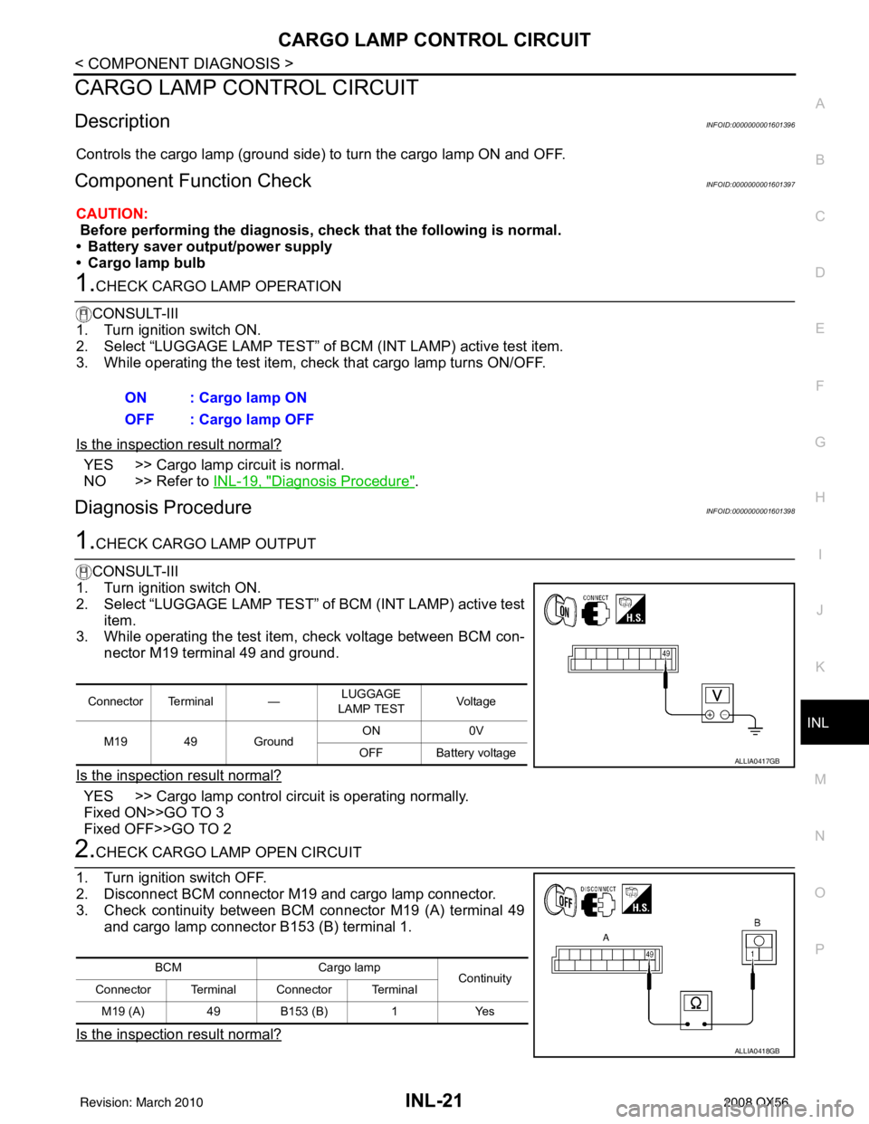
3. While operating the test item, check voltage between BCM con-
nector M19 terminal 49 and ground.
Is the inspection result normal?
YES >> Cargo lamp control circuit is operating normally.
Fixed ON>>GO TO 3
Fixed OFF>>GO TO 2
2.CHECK CARGO LAMP OPEN CIRCUIT
1. Turn ignition switch OFF.
2. Disconnect BCM connector M19 and cargo lamp connector.
3. Check continuity between BCM connector M19 (A) terminal 49 and cargo lamp connector B153 (B) terminal 1.
Is the inspection result normal?
ON : Cargo lamp ON
OFF : Cargo lamp OFF
Connector Terminal — LUGGAGE
LAMP TEST Vo l ta g e
M19 49 Ground ON
0V
OFF Battery voltage
ALLIA0417GB
BCM Cargo lamp
Continuity
Connector Terminal Connector Terminal
M19 (A) 49B153 (B) 1Yes
ALLIA0418GB
Revision: March 2010 2008 QX56
Page 2406 of 4083
IGNITION KEYHOLE ILLUMINATION CONTROL CIRCUIT
INL-23
< COMPONENT DIAGNOSIS >
C
D E
F
G H
I
J
K
M A
B
INL
N
O P
IGNITION KEYHOLE ILLUMI NATION CONTROL CIRCUIT
DescriptionINFOID:0000000001601399
Controls the ignition keyhole illumination (ground side) to turn the ignition keyhole illumination ON and OFF.
Component Function CheckINFOID:0000000001601400
CAUTION:
Before performing the diagnosis, check that the following is normal.
• Battery saver output/power supply circuit
• Ignition keyhole il lumination bulb
1.CHECK IGNITION KEYHOLE ILLUMINATION OPERATION
CONSULT-III
1. Turn the ignition switch ON.
2. Select “IGN ILLUM” of BCM (INT LAMP) active test item.
3. While operating the test item, check that the ignition keyhole illumination turns ON/OFF
Is the inspection result normal?
YES >> Ignition keyhole illumination circuit is normal.
NO >> Refer to INL-23, "
Diagnosis Procedure".
Diagnosis ProcedureINFOID:0000000001601401
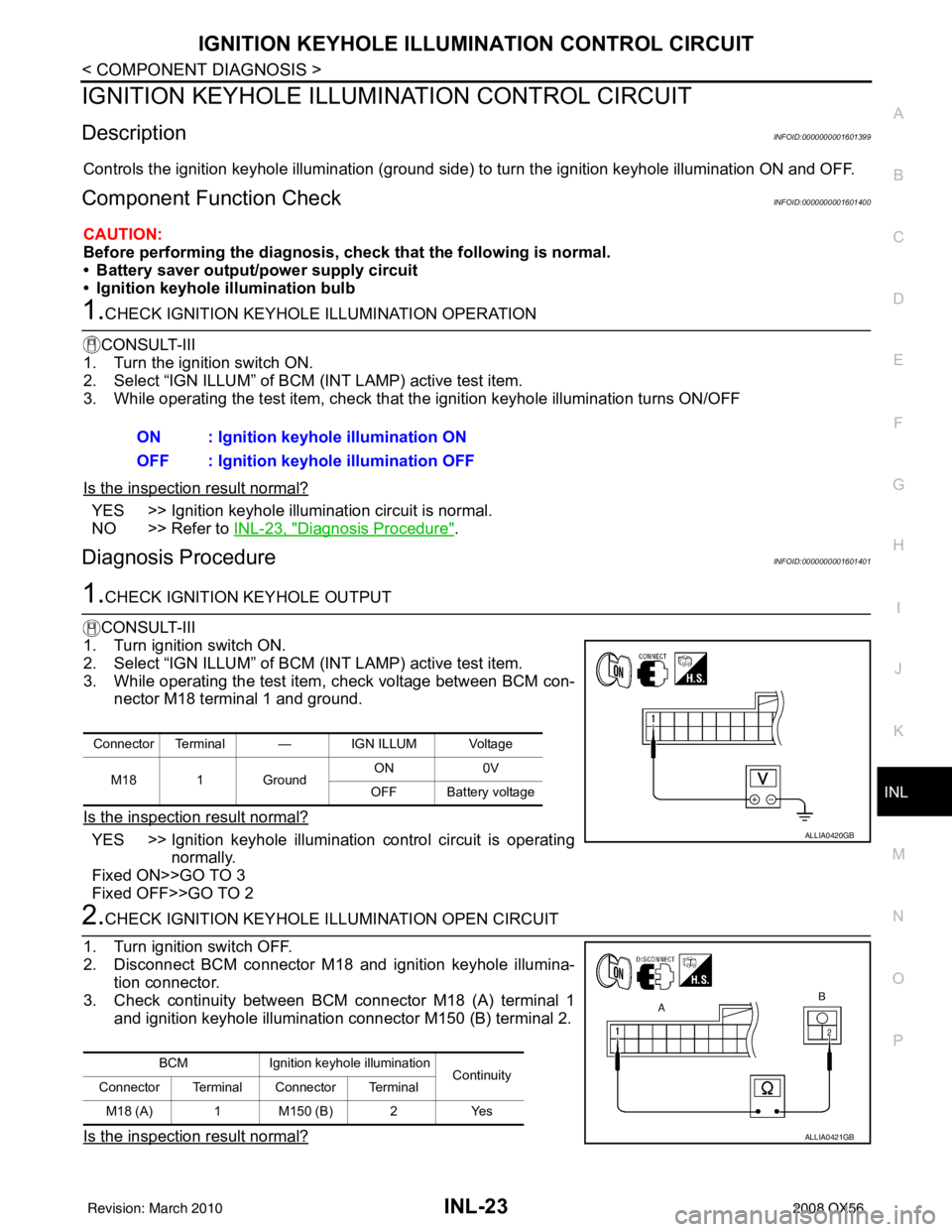
1.CHECK IGNITION KEYHOLE OUTPUT
CONSULT-III
1. Turn ignition switch ON.
2. Select “IGN ILLUM” of BCM (INT LAMP) active test item.
3. While operating the test item, check voltage between BCM con- nector M18 terminal 1 and ground.
Is the inspection result normal?
YES >> Ignition keyhole illumination control circuit is operating normally.
Fixed ON>>GO TO 3
Fixed OFF>>GO TO 2
2.CHECK IGNITION KEYHOLE I LLUMINATION OPEN CIRCUIT
1. Turn ignition switch OFF.
2. Disconnect BCM connector M18 and ignition keyhole illumina- tion connector.
3. Check continuity between BCM connector M18 (A) terminal 1 and ignition keyhole illumination connector M150 (B) terminal 2.
Is the inspection result normal?
ON : Ignition keyhole illumination ON
OFF : Ignition keyhole illumination OFF
Connector Terminal — IGN ILLUM Voltage
M18 1 Ground ON
0V
OFF Battery voltage
ALLIA0420GB
BCM Ignition keyhole illumination
Continuity
Connector Terminal Connector Terminal
M18 (A) 1 M150 (B) 2 Yes
ALLIA0421GB
Revision: March 2010 2008 QX56
Page 2439 of 4083
INL-56
< SYMPTOM DIAGNOSIS >
INTERIOR LIGHTING SYSTEM SYMPTOMS
SYMPTOM DIAGNOSIS
INTERIOR LIGHTING SYSTEM SYMPTOMS
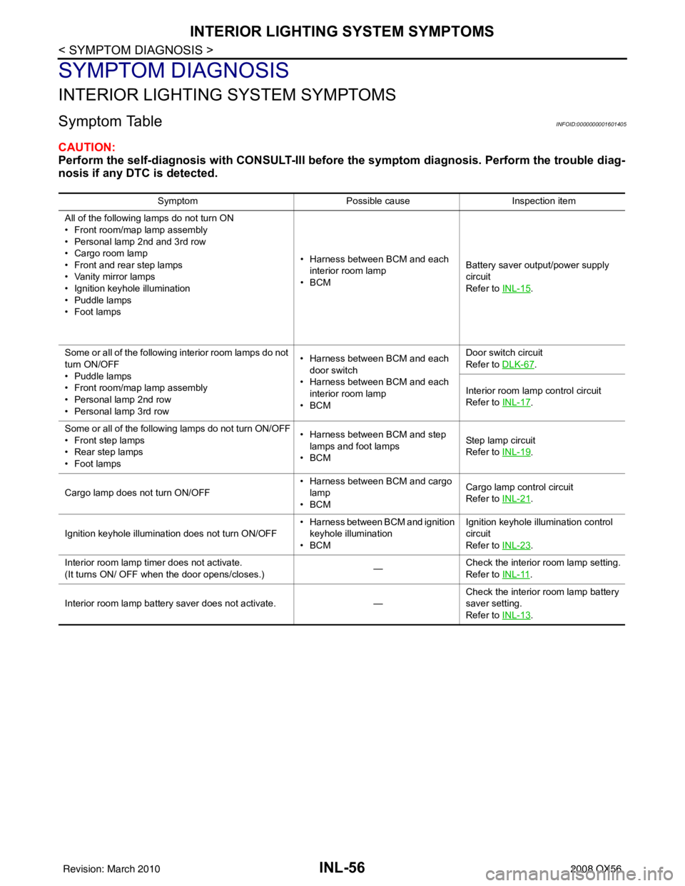
Symptom TableINFOID:0000000001601405
CAUTION:
Perform the self-diagnosis with CONSULT-III before the symptom diagnosis. Perform the trouble diag-
nosis if any DTC is detected.
Symptom Possible causeInspection item
All of the following lamps do not turn ON
• Front room/map lamp assembly
• Personal lamp 2nd and 3rd row
• Cargo room lamp
• Front and rear step lamps
• Vanity mirror lamps
• Ignition keyhole illumination
• Puddle lamps
•Foot lamps • Harness between BCM and each
interior room lamp
•BCM Battery saver output/power supply
circuit
Refer to
INL-15
.
Some or all of the following interior room lamps do not
turn ON/OFF
• Puddle lamps
• Front room/map lamp assembly
• Personal lamp 2nd row
• Personal lamp 3rd row • Harness between BCM and each
door switch
• Harness between BCM and each interior room lamp
•BCM Door switch circuit
Refer to
DLK-67
.
Interior room lamp control circuit
Refer to INL-17
.
Some or all of the following lamps do not turn ON/OFF
• Front step lamps
• Rear step lamps
•Foot lamps • Harness between BCM and step
lamps and foot lamps
•BCM Step lamp circuit
Refer to
INL-19
.
Cargo lamp does not turn ON/OFF • Harness between BCM and cargo
lamp
•BCM Cargo lamp co
ntrol circuit
Refer to INL-21
.
Ignition keyhole illumination does not turn ON/OFF • Harness between BCM and ignition
keyhole illumination
•BCM Ignition keyhole illumination control
circuit
Refer to
INL-23
.
Interior room lamp timer does not activate.
(It turns ON/ OFF when the door opens/closes.) —Check the interior room lamp setting.
Refer to
INL-11
.
Interior room lamp battery saver does not activate. —Check the interior room lamp battery
saver setting.
Refer to
INL-13
.
Revision: March 2010 2008 QX56