2008 INFINITI QX56 battery
[x] Cancel search: batteryPage 2448 of 4083
ILLUMINATIONINL-65
< ON-VEHICLE REPAIR >
C
DE
F
G H
I
J
K
M A
B
INL
N
O P
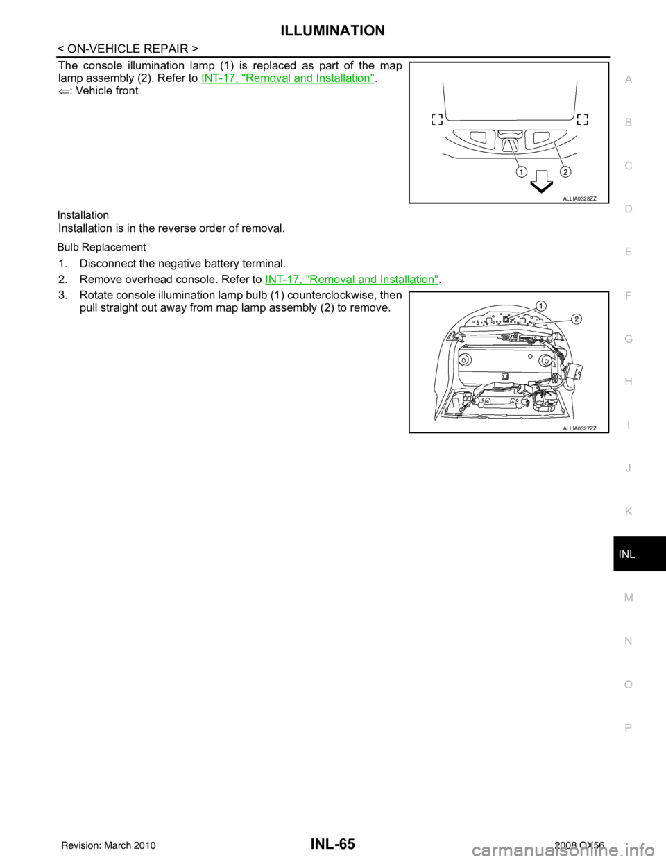
The console illumination lamp (1) is replaced as part of the map
lamp assembly (2). Refer to INT-17, "
Removal and Installation".
⇐ : Vehicle front
Installation
Installation is in the reverse order of removal.
Bulb Replacement
1. Disconnect the negative battery terminal.
2. Remove overhead console. Refer to INT-17, "
Removal and Installation".
3. Rotate console illumination lamp bulb (1) counterclockwise, then pull straight out away from map lamp assembly (2) to remove.
ALLIA0328ZZ
ALLIA0327ZZ
Revision: March 2010 2008 QX56
Page 2450 of 4083
INT-1
BODY INTERIOR
C
DE
F
G H
I
K L
M
SECTION INT
A
B
INT
N
O P
CONTENTS
INTERIOR
SYMPTOM DIAGNOSIS ..... ..........................2
SQUEAK AND RATTLE TROUBLE DIAG-
NOSES ........................ ........................................
2
Work Flow ........................................................... ......2
Generic Squeak and Rattle Troubleshooting ............4
Diagnostic Worksheet ...............................................6
PRECAUTION ...............................................8
PRECAUTIONS .............................................. .....8
Precaution for Supplemental Restraint System
(SRS) "AIR BAG" and "SEAT BELT PRE-TEN-
SIONER" ............................................................. ......
8
Precaution Necessary for Steering Wheel Rota-
tion After Battery Disconnect ............................... ......
8
Service Notice ...........................................................9
PREPARATION ...........................................10
PREPARATION .............................................. ....10
Special Service Tool ............................................ ....10
Commercial Service Tool ........................................10
ON-VEHICLE REPAIR .................................11
DOOR FINISHER ..............................................11
Removal and Installation ..................................... ....11
BODY SIDE TRIM .............................................14
Removal and Installation .........................................14
FLOOR TRIM ....................................................16
Removal and Installation .........................................16
HEADLINING ....................................................17
Removal and Installation .........................................17
LUGGAGE FLOOR TRIM .................................19
Removal and Installation .........................................19
BACK DOOR TRIM ...........................................21
Removal and Installation ..................................... ....21
Revision: March 2010 2008 QX56
Page 2457 of 4083
INT-8
< PRECAUTION >
PRECAUTIONS
PRECAUTION
PRECAUTIONS
Precaution for Supplemental Restraint System (SRS) "AIR BAG" and "SEAT BELT
PRE-TENSIONER"
INFOID:0000000004900856
The Supplemental Restraint System such as “A IR BAG” and “SEAT BELT PRE-TENSIONER”, used along
with a front seat belt, helps to reduce the risk or severity of injury to the driver and front passenger for certain
types of collision. This system includes seat belt switch inputs and dual stage front air bag modules. The SRS
system uses the seat belt switches to determine the front air bag deployment, and may only deploy one front
air bag, depending on the severity of a collision and w hether the front occupants are belted or unbelted.
Information necessary to service the system safely is included in the SR and SB section of this Service Man-
ual.
WARNING:
• To avoid rendering the SRS inopera tive, which could increase the risk of personal injury or death in
the event of a collision which would result in air bag inflation, all maintenance must be performed by
an authorized NISSAN/INFINITI dealer.
• Improper maintenance, including in correct removal and installation of the SRS, can lead to personal
injury caused by unintent ional activation of the system. For re moval of Spiral Cable and Air Bag
Module, see the SR section.
• Do not use electrical test equipmen t on any circuit related to the SRS unless instructed to in this
Service Manual. SRS wiring harn esses can be identified by yellow and/or orange harnesses or har-
ness connectors.
PRECAUTIONS WHEN USING POWER TOOLS (AIR OR ELECTRIC) AND HAMMERS
WARNING:
• When working near the Airbag Diagnosis Sensor Unit or other Airbag System sensors with the Igni-
tion ON or engine running, DO NOT use air or electri c power tools or strike near the sensor(s) with a
hammer. Heavy vibration could activate the sensor( s) and deploy the air bag(s), possibly causing
serious injury.
• When using air or electric power tools or hammers , always switch the Ignition OFF, disconnect the
battery, and wait at least 3 minu tes before performing any service.
Precaution Necessary for Steering W heel Rotation After Battery Disconnect
INFOID:0000000004900857
NOTE:
• This Procedure is applied only to models with Intelligent Key system and NATS (NISSAN ANTI-THEFT SYS-
TEM).
• Remove and install all control units after disconnecting both battery cables with the ignition knob in the
″LOCK ″ position.
• Always use CONSULT-III to perform self-diagnosis as a part of each function inspection after finishing work.
If DTC is detected, perform trouble diagnosis according to self-diagnostic results.
For models equipped with the Intelligent Key system and NATS, an electrically controlled steering lock mech-
anism is adopted on the key cylinder.
For this reason, if the battery is disconnected or if the battery is discharged, the steering wheel will lock and
steering wheel rotation will become impossible.
If steering wheel rotation is required when battery pow er is interrupted, follow the procedure below before
starting the repair operation.
OPERATION PROCEDURE
1. Connect both battery cables. NOTE:
Supply power using jumper cables if battery is discharged.
2. Use the Intelligent Key or mechanical key to turn the ignition switch to the ″ACC ″ position. At this time, the
steering lock will be released.
3. Disconnect both battery cables. The steering lock will remain released and the steering wheel can be rotated.
4. Perform the necessary repair operation.
Revision: March 2010 2008 QX56
Page 2458 of 4083
PRECAUTIONSINT-9
< PRECAUTION >
C
DE
F
G H
I
K L
M A
B
INT
N
O P
5. When the repair work is completed, return the ignition switch to the ″LOCK ″ position before connecting
the battery cables. (At this time, the steering lock mechanism will engage.)
6. Perform a self-diagnosis check of al l control units using CONSULT-III.
Service NoticeINFOID:0000000001609867
• When removing or installing various parts, place a cloth or padding on the vehicle body to prevent scratches.
• Handle trim, molding, instruments, grille, etc. carefully during removing or installing. Be careful not to soil or
damage them.
• Apply sealing compound where necessary when installing parts.
• When applying sealing compound, be careful that the sealing compound does not protrude from parts.
• When replacing any metal parts (for example body outer panel, members, etc.), be sure to take rust preven-
tion measures.
Revision: March 2010 2008 QX56
Page 2460 of 4083
DOOR FINISHERINT-11
< ON-VEHICLE REPAIR >
C
DE
F
G H
I
K L
M A
B
INT
N
O P
ON-VEHICLE REPAIR
DOOR FINISHER
Removal and InstallationINFOID:0000000001611672
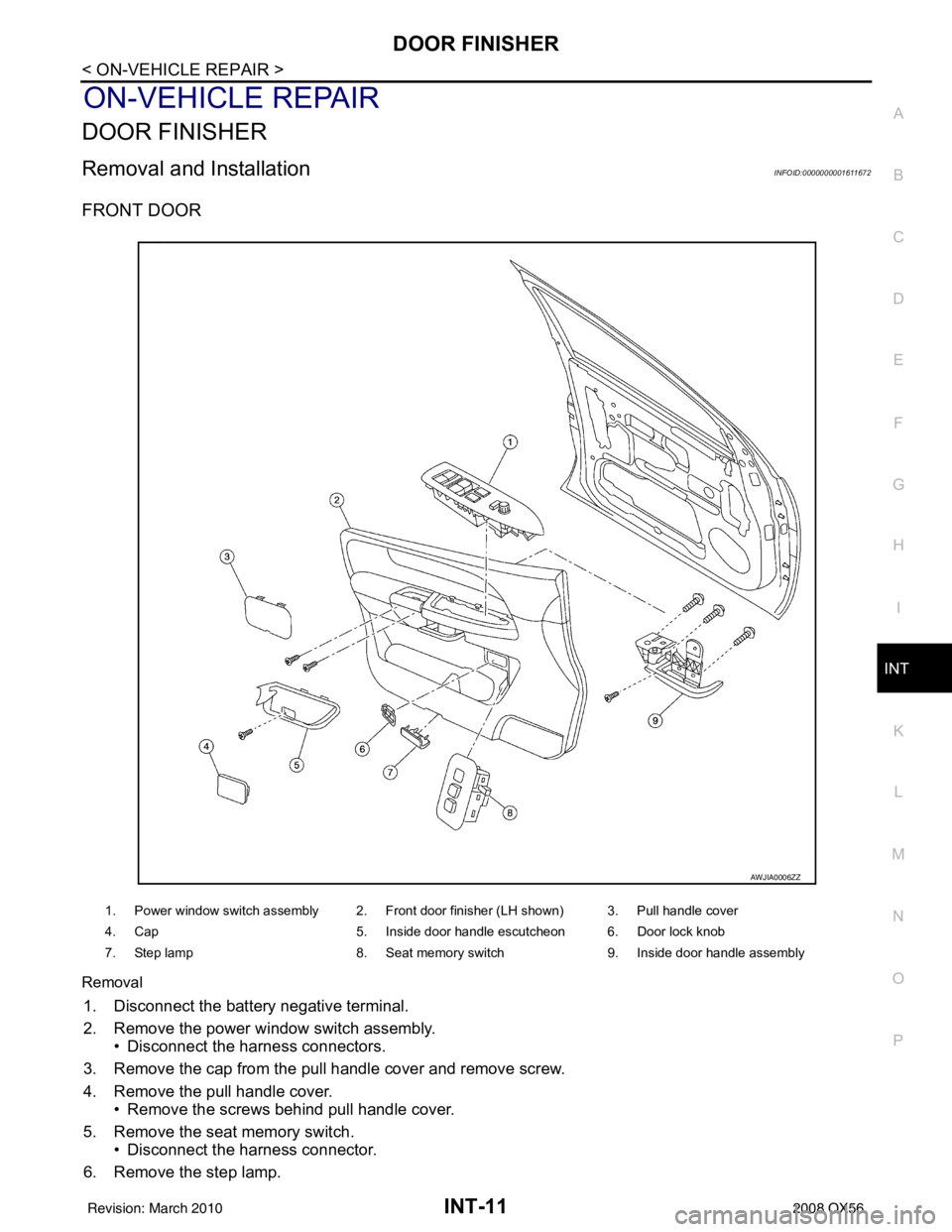
FRONT DOOR
Removal
1. Disconnect the battery negative terminal.
2. Remove the power window switch assembly. • Disconnect the harness connectors.
3. Remove the cap from the pull handle cover and remove screw.
4. Remove the pull handle cover. • Remove the screws behind pull handle cover.
5. Remove the seat memory switch. • Disconnect the harness connector.
6. Remove the step lamp.
1. Power window switch assembly 2. Front door finisher (LH shown) 3. Pull handle cover
4. Cap 5. Inside door handle escutcheon 6. Door lock knob
7. Step lamp 8. Seat memory switch 9. Inside door handle assembly
AWJIA0006ZZ
Revision: March 2010 2008 QX56
Page 2461 of 4083
INT-12
< ON-VEHICLE REPAIR >
DOOR FINISHER
• Disconnect the harness connector.
7. Remove the door finisher and disconnect the lock cable and handle cable from the inside door handle assembly. Refer to INT-11, "
Removal and Installation".
8. Remove the inside door handle assembly.
9. Remove door lock knob.
Installation
Installation is in the reverse order of removal.
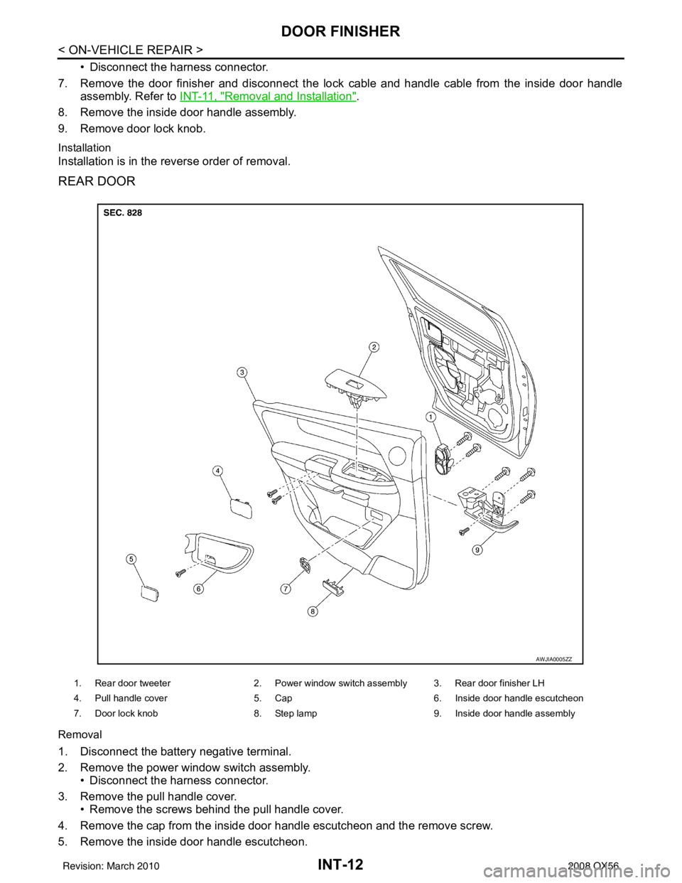
REAR DOOR
Removal
1. Disconnect the battery negative terminal.
2. Remove the power window switch assembly. • Disconnect the harness connector.
3. Remove the pull handle cover. • Remove the screws behind the pull handle cover.
4. Remove the cap from the inside door handle escutcheon and the remove screw.
5. Remove the inside door handle escutcheon.
1. Rear door tweeter 2. Power window switch assembly 3. Rear door finisher LH
4. Pull handle cover 5. Cap6. Inside door handle escutcheon
7. Door lock knob 8. Step lamp9. Inside door handle assembly
AWJIA0005ZZ
Revision: March 2010 2008 QX56
Page 2467 of 4083
INT-18
< ON-VEHICLE REPAIR >
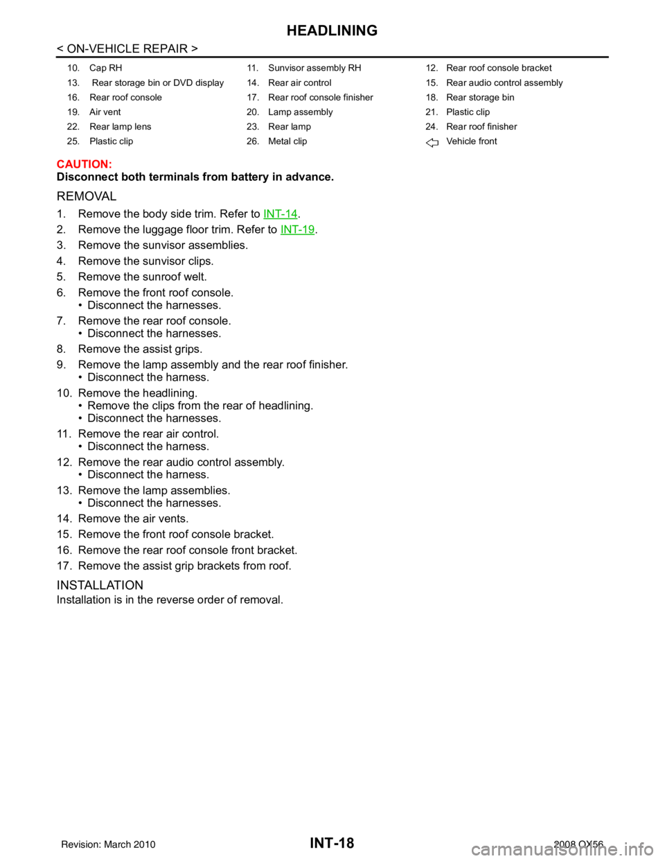
HEADLINING
CAUTION:
Disconnect both terminals from battery in advance.
REMOVAL
1. Remove the body side trim. Refer to INT-14.
2. Remove the luggage floor trim. Refer to INT-19
.
3. Remove the sunvisor assemblies.
4. Remove the sunvisor clips.
5. Remove the sunroof welt.
6. Remove the front roof console. • Disconnect the harnesses.
7. Remove the rear roof console. • Disconnect the harnesses.
8. Remove the assist grips.
9. Remove the lamp assembly and the rear roof finisher. • Disconnect the harness.
10. Remove the headlining. • Remove the clips from the rear of headlining.
• Disconnect the harnesses.
11. Remove the rear air control. • Disconnect the harness.
12. Remove the rear audio control assembly. • Disconnect the harness.
13. Remove the lamp assemblies. • Disconnect the harnesses.
14. Remove the air vents.
15. Remove the front roof console bracket.
16. Remove the rear roof console front bracket.
17. Remove the assist grip brackets from roof.
INSTALLATION
Installation is in the reverse order of removal.
10. Cap RH 11. Sunvisor assembly RH12. Rear roof console bracket
13. Rear storage bin or DVD display 14. Rear air control 15. Rear audio control assembly
16. Rear roof console 17. Rear roof console finisher18. Rear storage bin
19. Air vent 20. Lamp assembly21. Plastic clip
22. Rear lamp lens 23. Rear lamp24. Rear roof finisher
25. Plastic clip 26. Metal clip Vehicle front
Revision: March 2010 2008 QX56
Page 2471 of 4083

IP-1
BODY INTERIOR
C
DE
F
G H
I
K L
M
SECTION IP
A
B
IP
N
O P
CONTENTS
INSTRUMENT PANEL
PRECAUTION ....... ........................................2
PRECAUTIONS .............................................. .....2
Precaution for Supplemental Restraint System
(SRS) "AIR BAG" and "SEAT BELT PRE-TEN-
SIONER" ............................................................. ......
2
Precaution Necessary for Steering Wheel Rota-
tion After Battery Disconnect ............................... ......
2
PREPARATION ............................................4
PREPARATION .............................................. .....4
Special Service Tool ........................................... ......4
Commercial Service Tool ..........................................4
SYMPTOM DIAGNOSIS ...............................5
SQUEAK AND RATTLE TROUBLE DIAG-
NOSES ........................ ........................................
5
Work Flow ........................................................... ......5
Generic Squeak and Rattle Troubleshooting ............7
Diagnostic Worksheet ...............................................9
ON-VEHICLE REPAIR .................................11
INSTRUMENT PANEL ASSEMBLY .............. ....11
Exploded View .................................................... ....11
Removal and Installation .........................................12
CLUSTER LID A ............................................. ....14
Exploded View .................................................... ....14
Removal and Installation .........................................14
CLUSTER LID C ...............................................15
Exploded View ..................................................... ....15
Removal and Installation .........................................15
INSTRUMENT LOWER PANEL RH AND
GLOVE BOX .....................................................
17
Exploded View .........................................................17
Removal and Installation .........................................17
INSTRUMENT UPPER PANEL RH ..................18
Exploded View .........................................................18
Removal and Installation .........................................18
A/T FINISHER ...................................................19
Removal and Installation .........................................19
FRONT CENTER CONSOLE ............................20
Exploded View .........................................................20
Removal and Installation .........................................20
REAR CENTER CONSOLE ..............................21
Removal and Installation .........................................21
DISASSEMBLY AND ASSEMBLY ..............22
FRONT CENTER CONSOLE ............................22
Exploded View ..................................................... ....22
Disassembly and Assembly .....................................23
REAR CENTER CONSOLE ..............................24
Exploded View .........................................................24
Disassembly and Assembly .....................................25
Revision: March 2010 2008 QX56